EP0869529A2 - Tube à décharge - Google Patents
Tube à décharge Download PDFInfo
- Publication number
- EP0869529A2 EP0869529A2 EP98302525A EP98302525A EP0869529A2 EP 0869529 A2 EP0869529 A2 EP 0869529A2 EP 98302525 A EP98302525 A EP 98302525A EP 98302525 A EP98302525 A EP 98302525A EP 0869529 A2 EP0869529 A2 EP 0869529A2
- Authority
- EP
- European Patent Office
- Prior art keywords
- discharge
- trigger wires
- airtight cylinder
- sub
- discharge trigger
- Prior art date
- Legal status (The legal status is an assumption and is not a legal conclusion. Google has not performed a legal analysis and makes no representation as to the accuracy of the status listed.)
- Granted
Links
- 239000011810 insulating material Substances 0.000 claims description 4
- 239000000126 substance Substances 0.000 abstract description 24
- 238000004544 sputter deposition Methods 0.000 abstract description 23
- 238000000034 method Methods 0.000 abstract description 7
- 230000006866 deterioration Effects 0.000 description 8
- 238000010292 electrical insulation Methods 0.000 description 4
- 239000002184 metal Substances 0.000 description 3
- 229910052751 metal Inorganic materials 0.000 description 3
- 239000000843 powder Substances 0.000 description 3
- OKTJSMMVPCPJKN-UHFFFAOYSA-N Carbon Chemical compound [C] OKTJSMMVPCPJKN-UHFFFAOYSA-N 0.000 description 2
- 229910045601 alloy Inorganic materials 0.000 description 2
- 239000000956 alloy Substances 0.000 description 2
- 230000015572 biosynthetic process Effects 0.000 description 2
- 229910052799 carbon Inorganic materials 0.000 description 2
- 239000011248 coating agent Substances 0.000 description 2
- 238000000576 coating method Methods 0.000 description 2
- 229910001507 metal halide Inorganic materials 0.000 description 2
- 150000005309 metal halides Chemical class 0.000 description 2
- 229910001030 Iron–nickel alloy Inorganic materials 0.000 description 1
- 239000000919 ceramic Substances 0.000 description 1
- 238000007599 discharging Methods 0.000 description 1
- 238000002474 experimental method Methods 0.000 description 1
- 230000001939 inductive effect Effects 0.000 description 1
- 238000009413 insulation Methods 0.000 description 1
- 238000005476 soldering Methods 0.000 description 1
Images



Classifications
-
- H—ELECTRICITY
- H01—ELECTRIC ELEMENTS
- H01J—ELECTRIC DISCHARGE TUBES OR DISCHARGE LAMPS
- H01J17/00—Gas-filled discharge tubes with solid cathode
- H01J17/38—Cold-cathode tubes
- H01J17/40—Cold-cathode tubes with one cathode and one anode, e.g. glow tubes, tuning-indicator glow tubes, voltage-stabiliser tubes, voltage-indicator tubes
- H01J17/44—Cold-cathode tubes with one cathode and one anode, e.g. glow tubes, tuning-indicator glow tubes, voltage-stabiliser tubes, voltage-indicator tubes having one or more control electrodes
- H01J17/46—Cold-cathode tubes with one cathode and one anode, e.g. glow tubes, tuning-indicator glow tubes, voltage-stabiliser tubes, voltage-indicator tubes having one or more control electrodes for preventing and then permitting ignition but thereafter having no control
-
- H—ELECTRICITY
- H01—ELECTRIC ELEMENTS
- H01J—ELECTRIC DISCHARGE TUBES OR DISCHARGE LAMPS
- H01J17/00—Gas-filled discharge tubes with solid cathode
- H01J17/02—Details
- H01J17/30—Igniting arrangements
-
- H—ELECTRICITY
- H01—ELECTRIC ELEMENTS
- H01T—SPARK GAPS; OVERVOLTAGE ARRESTERS USING SPARK GAPS; SPARKING PLUGS; CORONA DEVICES; GENERATING IONS TO BE INTRODUCED INTO NON-ENCLOSED GASES
- H01T1/00—Details of spark gaps
- H01T1/20—Means for starting arc or facilitating ignition of spark gap
-
- H—ELECTRICITY
- H01—ELECTRIC ELEMENTS
- H01T—SPARK GAPS; OVERVOLTAGE ARRESTERS USING SPARK GAPS; SPARKING PLUGS; CORONA DEVICES; GENERATING IONS TO BE INTRODUCED INTO NON-ENCLOSED GASES
- H01T4/00—Overvoltage arresters using spark gaps
- H01T4/10—Overvoltage arresters using spark gaps having a single gap or a plurality of gaps in parallel
- H01T4/12—Overvoltage arresters using spark gaps having a single gap or a plurality of gaps in parallel hermetically sealed
Definitions
- the present invention relates to a discharge tube in which a pair of upper and lower discharge electrodes are vertically arranged, in an airtight cylinder made of insulating material, and are vertically opposed to each other in the axial direction.
- a discharge tube used for a "Switching Spark Gap (SSG)" for lighting a metal halide lamp and also used as an arrester for preventing generation of a surge voltage.
- SSG switching Spark Gap
- an upper discharge electrode 20a and a lower discharge electrode 20b are provided in this discharge tube, the profiles of which are cylindrical, which are made of a metal such as 42-alloy (iron-nickel alloy) and are arranged in an axial direction in an airtight cylinder 10 made of an insulating material such as a ceramic, and these upper discharge electrode 20a and lower discharge electrode 20b are arranged vertically opposed to each other. Between the fore end surfaces of the upper discharge electrode 20a and lower discharge electrode 20b, there is formed a discharge gap of a predetermined width for generating an electric discharge.
- the upper and lower opening ends of the airtight cylinder 10 are airtightly closed by covers 22a, 22b made of a metal such as 42-alloy which are attached to the upper discharge electrode 20a and the lower discharge electrode 20b.
- the covers 22a, 22b are airtightly joined, by means of soldering, onto metalized layers 12a, 12b which are formed on the upper and lower opening end surfaces of the airtight cylinder 10.
- a plurality of discharge trigger wires 30a are electrically connected to the upper discharge electrode 20a via the metalized layer 12a in the upper portion of the inner circumferential wall of the airtight cylinder 10.
- the plurality of discharge trigger wires 30a are arranged in the lateral direction, and the lower end portions of the discharge trigger wires 30a cross the center of the inner circumferential wall of the airtight cylinder 10.
- a plurality of discharge trigger wires 30b are electrically connected to the lower discharge electrode 20b via the metalized layer 12b in the lower portion of the inner circumferential wall of the airtight cylinder 10.
- the plurality of discharge trigger wires 30b are arranged in the lateral direction, and upper end portions of the discharge trigger wires 30b cross the center of the inner circumferential wall of the airtight cylinder 10.
- the plurality of discharge trigger wires 30a, 30b are alternately arranged in the lateral direction on the inner circumferential wall of the airtight cylinder 10.
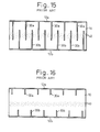
- the discharge tube shown in Figs. 14 and 15 is composed as described above.
- this discharge tube when a voltage higher than a predetermined value is impressed between the covers 22a, 22b attached to the upper discharge electrode 20a and the lower discharge electrode 20b, it is possible to generate an electrical discharge between the fore end surfaces of the upper discharge electrode 20a and the lower discharge electrode 20b.
- the discharge trigger wires 30a In order to prevent the deterioration of electrical insulation between the discharge trigger wires 30a, 30b, it is possible to arrange the discharge trigger wires 30a in such a manner that the discharge trigger wires 30a are electrically connected with the upper discharge electrode 20a while they are made to be short and made to come close to the upper end of the inner circumferential wall of the airtight cylinder 10 and that the discharge trigger wires 30b are electrically connected with the lower discharge electrode 20b while they are made to be short and made to come close to the lower end of the inner circumferential wall of the airtight cylinder 10.
- the discharge trigger wires 30a, 30b at positions close to the upper and the lower end of the inner circumferential wall of the airtight cylinder 10 which are distant from the centre of the inner circumferential wall of the airtight cylinder 10 to which the sputtering substances 40 scattered from the upper discharge electrode 20a and the lower discharge electrode 20b is made to adhere.
- a discharge tube in which an upper discharge electrode and lower discharge are arranged in an airtight cylinder made of insulating material, being vertically opposed to each other in the axial direction of the airtight cylinder, an upper end opening and lower end opening of the airtight cylinder are airtightly closed by covers to the upper discharge electrode and the lower discharge electrode, and discharge trigger wires are arranged on an inner circumferential wall of the airtight cylinder, the discharge trigger wires electrically connected with the upper discharge electrode, being arranged in an upper portion of the inner circumferential wall of the airtight cylinder; and the discharge trigger wires electrically connected with the lower discharge electrode, being arranged in a lower portion of the inner circumferential wall of the airtight cylinder, is characterised in that sub-discharge trigger wires are arranged at the centre of the inner circumferential wall of the airtight cylinder, the sub-discharge trigger wires being electrically insulated from the upper discharge electrode and the lower discharge electrode; and in that distances from the respective discharge trigger wire
- the discharge trigger wires electrically connected to the upper discharge electrode and the discharge trigger wires electrically connected to the lower discharge electrode are arranged in the upper and the lower portion of the inner circumferential wall of the airtight cylinder to which the sputtering substance generated by the upper and the lower discharge electrode in the process of discharge hardly adheres.
- the electrical insulating property between the discharge trigger wires arranged in the upper and the lower portion of the inner circumferential wall of the airtight cylinder is hardly affected or is not affected by the belt-shaped sputtering substance which is generated and made to adhere to the center of the inner circumferential wall of the airtight cylinder in the lateral direction when electrical discharge is conducted by the upper and the lower discharge electrode.
- the sub-discharge trigger wires are arranged at the center of the inner circumferential wall of the airtight cylinder, the distance between the end portions of the discharge trigger wires arranged between the upper and the lower portion of the inner circumferential wall of the airtight cylinder is electrically reduced via the sub-discharge trigger wires.
- An initial discharge is generated and stabilized at an early stage between the end portions of the sub-discharge triggers and the discharge triggers located close to them. Being facilitated by the initial discharge, a discharge is positively induced in quick response between the fore end surfaces of the upper and the lower discharge electrode.
- the discharge trigger wires extend from the upper or the lower portion on the inner circumferential wall of the airtight cylinder toward the center of the airtight cylinder, and the end surfaces of the sub-discharge trigger wires and the discharge trigger wires, which generate the initial discharge, are located close to the end surfaces of the upper and the lower discharge electrode generating the discharge. Therefore, compared with a discharge tube in which the initial discharge is generated between the end portions of the discharge trigger wires located in the upper and the lower portion of the airtight cylinder which are distant from the fore end surfaces of the upper and the lower electrode, the discharge can be positively generated in quick response between the fore end surfaces of the upper and the lower discharge electrode by the initial discharge generated between the end surfaces of the sub-discharge trigger wires and the discharge trigger wires.
- the initial discharge is generated between the end portions of the linear discharge trigger wires and the linear sub-discharge trigger wires, electrons for a creeping corona discharge used for inducing an initial discharge can effectively converge upon the end portions of the discharge trigger wires and the sub-discharge trigger wires.
- the initial discharge can be quickly and stably generated between the end surfaces of the discharge trigger wires and the sub-discharge trigger wires.
- the discharge tube of the present invention is preferably composed as follows.
- Sub-discharge trigger wires are arranged at the center of the inner circumferential wall of the airtight cylinder so that the end portions of the sub-discharge trigger wires can overlap with the fore end portions of the discharge trigger wires when a view is laterally taken in a direction perpendicular to the axis of the airtight cylinder.
- this discharge tube it is possible to generate the initial discharge in a wide range between the end portion side edges of the sub-discharge trigger wires and the fore end side edges of the discharge trigger wires, which overlap with each other at a predetermined distance when a view is laterally taken in a direction perpendicular to the axis of the airtight cylinder.
- the initial discharge is generated between the narrow fore end edges of the sub-discharge trigger wires and the narrow fore end edges of the discharge trigger wires
- the discharge tube of the present invention is preferably composed as follows.
- a plurality of sub-discharge trigger wires are arranged on the inner circumferential wall of the airtight cylinder at regular intervals, and discharge trigger wires are regularly arranged in a portion on the inner circumferential wall of the airtight cylinder between the respective sub-discharge trigger wires.
- the discharge trigger wires and/or the sub-discharge trigger wires are arranged in parallel with the axis of the airtight cylinder.
- the discharge trigger wires and/or the sub-discharge trigger wires are arranged oblique to the axis of the airtight cylinder.
- this discharge tube when a plurality of sub-discharge trigger wires and a plurality of discharge trigger wires, which are used for generating the initial discharge, are regularly arranged on the inner circumferential wall of the airtight cylinder, they can be positioned in a direction parallel with the axis of the airtight cylinder or in a direction oblique to the axis of the airtight cylinder.
- the discharge tube of the present invention is preferably composed as follows.
- the profiles and sizes of the discharge trigger wires are the same, and the profiles and sizes of the sub-discharge trigger wires are the same.
- This discharge tube is composed in such a manner that profiles and sizes of the discharge trigger wires are the same, and profiles and sizes of the sub-discharge trigger wires are the same. Accordingly, it is possible to prevent a portion of the discharge and the sub-discharge trigger wires from being damaged by the initial discharge generated between the discharge trigger wires and the sub-discharge trigger wires earlier than between other discharge and sub-discharge trigger wires.
- the discharge tube of the present invention is preferably composed as follows.
- the discharge trigger wires electrically connected to the upper discharge electrode and the discharge trigger wires electrically connected to the lower discharge electrode are alternately arranged on the inner circumferential wall of the airtight cylinder.
- the discharge trigger wires electrically connected to the upper discharge electrode and the discharge trigger wires electrically connected to the lower discharge electrode are arranged on the inner circumferential wall of the airtight cylinder being opposed to each other.
- the discharge trigger wires electrically connected with the upper discharge electrode and/or the discharge trigger wires electrically connected with the lower electrode can be arranged in a portion on the inner circumferential wall of the airtight cylinder positioned between the sub-discharge trigger wires, and the initial discharge can be generated between the end portions of the discharge trigger wires and the sub-discharge trigger wires located close to them.
- the discharge tube of the present invention is preferably composed as follows. The following relational expression is satisfied, B/2 ⁇ H ⁇ (A - B)/2 where A is a height of the airtight cylinder, B is a discharge gap between the fore end surfaces of the upper and the lower discharge electrode, and H is a distance between an upper end of the sub-discharge trigger wire and an upper end edge of the airtight cylinder opposed to the upper end of the sub-discharge trigger wire and H is also a distance between a lower end of the sub-discharge trigger wire and a lower end edge of the airtight cylinder opposed to the lower end of the sub-discharge trigger wire.
- the discharge starting voltage generated between the upper and the lower discharge electrode the first time can be made substantially equal to the discharge starting voltage generated between the same upper and the lower discharge electrode the next time and after.
- the discharge tube of the present invention is preferably composed as follows.
- the lower end portions of the discharge trigger wires arranged in the upper portion of the inner circumferential wall of the airtight cylinder are located at the same positions as the position of the fore end face of the upper discharge electrode or at positions higher than the position of the fore end face of the upper discharge electrode when a view is laterally taken in a direction perpendicular to the axis of the airtight cylinder, and upper end portions of the discharge trigger wires arranged in the lower portion of the inner circumferential wall of the airtight cylinder are located at the same positions as the position of the fore end surface of the lower discharge electrode or alternatively at the positions lower than the position of the fore end surface of the lower discharge electrode when a view is laterally taken in a direction perpendicular to the axis of the airtight cylinder.
- this discharge tube it is possible to arrange the discharge trigger wires in the upper and the lower portion of the inner circumferential wall of the airtight cylinder while not arranging them at the center of the inner circumferential wall of the airtight cylinder to which the sputtering substance adheres, wherein the sputtering substance is composed of metallic powder generated in the process of a discharge from the fore end surfaces of the upper and the lower electrode on which coating for the formation of the discharge surface is coated. Accordingly, it is possible to prevent the deterioration of electrical insulation, which is caused by the sputtering substance, between the discharge trigger wires arranged in the upper and the lower portion of the inner circumferential wall of the airtight cylinder.
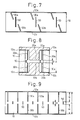
- Figs. 1 to 7 are development views of the inner circumferential wall of the airtight cylinder. Embodiments of the discharge tube will be explained as follows.
- a plurality of narrow belt-shaped sub-discharge trigger wires 50 made of carbon are arranged at the center of the inner circumferential wall of the airtight cylinder 10 in the lateral direction at regular intervals.
- a plurality of sub-discharge trigger wires 50 are arranged in parallel with the axis of the airtight cylinder 10.
- a plurality of sub-discharge trigger wires 50 are arranged oblique to the axis of the airtight cylinder 10.
- a plurality of narrow belt-shaped trigger wires 30a in the lateral direction which continue to the metalized layer 12a formed on the opening end surface at the upper end of the airtight cylinder 10.
- a plurality of narrow belt-shaped trigger wires 30b in the lateral direction which continue to the metalized layer 12b formed on the opening end surface at the lower end of the airtight cylinder 10.
- a plurality of discharge trigger wires 30a, 30b and a plurality of sub-discharge trigger wires 50 are regularly arranged so that the distances between the discharge trigger wires 30a, 30b and the sub-discharge trigger wires 50 located close to them are equal.
- the discharge trigger wires 30a, 30b are alternately arranged in the lateral direction on the inner circumferential wall of the airtight cylinder 10.
- the discharge trigger wires 30a, 30b are arranged in the middle portions of the inner circumferential wall of the airtight cylinder 10 located between the sub-discharge trigger wires 50.
- the discharge trigger wires 30a, 30b are arranged in the lateral direction being vertically opposed to each other on the inner circumferential wall of the airtight cylinder 10.
- the discharge trigger wires 30a, 30b are arranged in the middle portions of the inner circumferential wall of the airtight cylinder 10 located between the sub-discharge trigger wires 50.
- the discharge trigger wires 30a, 30b are alternately arranged in the lateral direction on the inner circumferential wall of the airtight cylinder 10.
- the discharge trigger wires 30a, 30b are arranged at portions of the inner circumferential wall of the airtight cylinder 10 located close to the end portions of the sub-discharge trigger wires 50.
- the discharge trigger wires 30a, 30b are alternately arranged in the lateral direction on the inner circumferential wall of the airtight cylinder 10.
- the discharge trigger wires 30a, 30b are arranged at portions of the inner circumferential wall of the airtight cylinder 10 located close to the end portions of the sub-discharge trigger wires 50.
- the discharge trigger wires 30a, 30b are arranged in the lateral direction being substantially obliquely opposed to each other in the vertical direction on the inner circumferential wall of the airtight cylinder 10.
- the discharge trigger wires 30a, 30b are arranged in the middle portions of the inner circumferential wall of the airtight cylinder 10 located between the sub-discharge trigger wires 50.
- the discharge trigger wires 30a, 30b are alternately arranged in the lateral direction on the inner circumferential wall of the airtight cylinder 10.
- the discharge trigger wires 30a, 30b are arranged at portions of the inner circumferential wall of the airtight cylinder 10 located close to the end portions of the sub-discharge trigger wires 50.
- the discharge trigger wires 30a, 30b are arranged in the lateral direction being substantially opposed to each other in the vertical direction on the inner circumferential wall of the airtight cylinder 10.
- the discharge trigger wires 30a, 30b are arranged at portions of the inner circumferential wall of the airtight cylinder 10 located close to the end portions of the sub-discharge trigger wires 50.
- the sub-trigger wires 50 are extended in the vertical direction or in the oblique direction of the center of the inner circumferential wall of the airtight cylinder 10 so that the end portions of the sub-discharge trigger wires 50 can overlap with the fore end portions of the discharge trigger wires 30a, 30b when a view is laterally taken in a direction perpendicular to the axis of the airtight cylinder 10.
- the widths and lengths of the discharge trigger wires 30a, 30b are the same, and widths and lengths of the sub-discharge trigger wires 50 are the same.
- the profiles and sizes of the discharge trigger wires 30a, 30b are the same, and the profiles and sizes of the sub-discharge trigger wires 50 are the same.
- the distance between the end portions of the discharge trigger wires 30a, 30b arranged at the upper and the lower portion of the inner circumferential wall of the airtight cylinder 10 is electrically reduced via the sub-discharge trigger wires 50.
- An initial discharge is generated and stabilized at an early stage between the end portions of the sub-discharge triggers 50 and the discharge triggers 30a, 30b located close to them. Being facilitated by the initial discharge, a discharge is positively induced between the fore end surfaces of the upper discharge electrode 20a and the lower discharge electrode 20b in quick response.
- the end surfaces of the sub-discharge trigger wires 50 and the discharge trigger wires 30a, 30b, which generate the initial discharge, are located close to the end surfaces of the upper discharge electrode 20a and the lower discharge electrode 20b by which the discharge is generated. Therefore, the discharge can be positively induced in quick response between the fore end surfaces of the upper discharge electrode 20a and the lower discharge electrode 20b by the initial discharge induced between the end surfaces of the sub-discharge trigger wires 50 and the discharge trigger wires 30a, 30b.
- the initial discharge is generated between the end portions of the narrow band-shaped discharge trigger wires 30a, 30b and the narrow band-shaped sub-discharge trigger wires 50 located close to them, electrons for a creeping corona discharge used for generating the initial discharge can effectively converge upon the end portions of the discharge trigger wires 30a, 30b and the sub-discharge trigger wires 50.
- the initial discharge can be quickly and stably generated between the end surfaces of the discharge trigger wires 30a, 30b and the sub-discharge trigger wires 50.
- the plurality of discharge trigger wires 30a, 30b and sub-discharge trigger wires 50 are arranged so that the distances between the respective discharge trigger wires 30a, 30b and the sub-discharge trigger wires 50 located close to them can be the same. Due to the above arrangement, the initial discharges can be simultaneously generated between the end portions of the discharge trigger wires 30a, 30b and the sub-discharge trigger wires 50 located close to them.
- the initial discharges are generated only between the end surfaces of a portion of discharge trigger wires 30a, 30b arranged on the inner circumferential wall of the airtight cylinder 10 and the sub-discharge trigger wires 50, and it is possible to prevent the portion of the discharge trigger wires 30a, 30b and sub-discharge trigger wires 50 being damaged earlier than other discharge trigger wires 30a, 30b and sub-discharge trigger wires 50.
- Profiles and sizes of the discharge trigger wires 30a, 30b are the same, and profiles and sizes of the sub-discharge trigger wires 50 are the same. Therefore, by the initial discharges generated between the end portions of the discharge trigger wires 30a, 30b and the sub-discharge trigger wires 50, it is possible to prevent a portion of discharge trigger wires 30a, 30b and sub-discharge trigger wires 50 from being damaged earlier than other discharge trigger wires 30a, 30b and sub-discharge trigger wires 50. Therefore, deterioration of the life of the discharge tube can be prevented.
- Figs. 8 and 9 are views showing another preferable embodiment of the discharge tube of the present invention.
- Fig. 8 is a front cross-sectional view of the discharge tube
- Fig. 9 is a development view of the inner circumferential wall of the airtight cylinder. This discharge tube will be explained below.
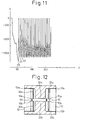
- the vertical axis represents discharge voltage V generated between the upper discharge electrode 20a and the lower discharge electrode 20b, and one graduation of the vertical axis is set at -200 V.
- the horizontal axis represents time t, and one graduation of the horizontal axis is set at 50 msec.
- A is a height of the airtight cylinder 10
- B is a discharge gap between the fore end surfaces of the upper discharge electrode 20a and the lower discharge electrode 20b
- H is a distance between the upper end of the sub-discharge trigger wire 50 and the upper end edge of the airtight cylinder 10 opposed to the upper end of the sub-discharge trigger wire
- H is also a distance between the lower end of the sub-discharge trigger wire 50 and the lower end edge of the airtight cylinder 10 opposed to the lower end of the sub-discharge trigger wire.
- the vertical axis represents discharge voltage V generated between the upper discharge electrode 20a and the lower discharge electrode 20b, and one graduation of the vertical axis is set at -200 V.
- the horizontal axis represents time t, and one graduation of the horizontal axis is set at 50 msec.
- the initial discharge starting voltage V0 generated between the fore end surfaces of the upper discharge electrode 20a and the lower discharge electrode 20b can be made to be substantially the same as the next time discharge starting voltages V1, V2, V3 ⁇ generated between the same fore end surfaces of the upper discharge electrode 20a and the lower discharge electrode 20b.
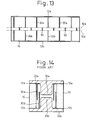
- Figs. 12 and 13 are views showing still another preferable embodiment of the discharge tube of the present invention.
- Fig. 12 is a front cross-sectional view of the discharge tube
- Fig. 13 is a development view of the inner circumferential wall of the airtight cylinder. This discharge tube will be explained as follows.
- the lower end portions of the discharge trigger wires 30a arranged in the upper portion of the inner circumferential wall of the airtight cylinder 10 are located at the same positions as those of the fore end faces of the upper discharge electrodes 20a or at the positions higher than those of the fore end faces of the upper discharge electrodes 20a when a view is laterally taken in a direction perpendicular to the axis of the airtight cylinder 10, and the upper end portions of the discharge trigger wires 30b arranged in the lower portion of the inner circumferential wall of the airtight cylinder 10 are located at the same positions as those of the fore end surfaces of the lower discharge electrodes 20b or alternatively at the positions lower than the fore end surfaces of the lower discharge electrodes 20b when a view is laterally taken in a direction perpendicular to the axis of the airtight cylinder.
- the discharge trigger wires 30a, 30b in the upper and the lower portion of the inner circumferential wall of the airtight cylinder 10 while not arranging them at the center of the inner circumferential wall of the airtight cylinder 10 to which the sputtering substance adheres in a belt-shape, wherein the sputtering substance is composed of metallic powder generated in the process of discharge from the fore end surfaces of the upper and the lower electrode on which coating for the formation of the discharge surface is coated, so that discharge can be stabilized at an early stage.
- the lower end of the upper discharge electrode 20a is located at the same position as that of the upper boundary 10a of the inner circumferential wall portion of the airtight cylinder 10 to which the sputtering substance 40 adheres in a belt-shape, or alternatively at the position higher than that of the upper boundary 10a of the inner circumferential wall portion of the airtight cylinder 10 to which the sputtering substance 40 adheres in a belt-shape when a view is taken in the lateral direction perpendicular to the axis of the airtight cylinder 10.
- the upper end of the lower discharge electrode 20b is located at the same position as that of the lower boundary 10b of the inner circumferential wall portion of the airtight cylinder 10 to which the sputtering substance 40 adheres in a belt-shape, or alternatively at the position lower than that of the lower boundary 10a of the inner circumferential wall portion of the airtight cylinder 10 to which the sputtering substance 40 adheres in a belt-shape when a view is taken in the lateral direction perpendicular to the axis of the airtight cylinder 10.
- two or more discharge trigger wires 30a and/or discharge trigger wires 30b may be arranged in the inner circumferential wall portion of the airtight cylinder 10 located between the sub-discharge trigger wires 50.
- two or more discharge trigger wires 30a and/or discharge trigger wires 30b may be arranged being opposed to each other. Even when the above arrangement is adopted, in the same manner as that of the discharge tube described before, it is possible to provide a discharge tube capable of discharging in quick response, in which there is no possibility of deterioration of the electrical insulating property between the discharge trigger wires 30a, 30b.
- the discharge tube of the present invention it is possible to prevent the deterioration of the electrical insulating property, which is caused by the sputtering substance when discharge is conducted by the upper and the lower discharge electrode, between the discharge trigger wires by which the initial discharge is generated.
Landscapes
- Discharge Lamps And Accessories Thereof (AREA)
- Lasers (AREA)
- Insulated Conductors (AREA)
Applications Claiming Priority (6)
| Application Number | Priority Date | Filing Date | Title |
|---|---|---|---|
| JP9825997 | 1997-03-31 | ||
| JP9825997 | 1997-03-31 | ||
| JP98259/97 | 1997-03-31 | ||
| JP362877/97 | 1997-12-12 | ||
| JP9362877A JPH10335042A (ja) | 1997-03-31 | 1997-12-12 | 放電管 |
| JP36287797 | 1997-12-12 |
Publications (3)
| Publication Number | Publication Date |
|---|---|
| EP0869529A2 true EP0869529A2 (fr) | 1998-10-07 |
| EP0869529A3 EP0869529A3 (fr) | 1999-01-20 |
| EP0869529B1 EP0869529B1 (fr) | 2003-05-21 |
Family
ID=26439454
Family Applications (1)
| Application Number | Title | Priority Date | Filing Date |
|---|---|---|---|
| EP98302525A Expired - Lifetime EP0869529B1 (fr) | 1997-03-31 | 1998-03-30 | Tube à décharge |
Country Status (5)
| Country | Link |
|---|---|
| US (1) | US6025672A (fr) |
| EP (1) | EP0869529B1 (fr) |
| JP (1) | JPH10335042A (fr) |
| KR (1) | KR100349732B1 (fr) |
| DE (1) | DE69814728T2 (fr) |
Cited By (6)
| Publication number | Priority date | Publication date | Assignee | Title |
|---|---|---|---|---|
| EP1069589A3 (fr) * | 1999-07-16 | 2002-07-31 | Shinko Electric Industries Co. Ltd. | Tube à décharge électrique |
| EP1239562A3 (fr) * | 2001-03-09 | 2003-09-17 | Shinko Electric Industries Co. Ltd. | Tube-interrupteur à décharge électrique rempli de gaz |
| EP1237243A3 (fr) * | 2001-03-02 | 2003-09-17 | Shinko Electric Industries Co. Ltd. | Tube-interrupteur à décharge électrique rempli de gaz |
| EP1443539A3 (fr) * | 2003-01-30 | 2006-01-04 | Shinko Electric Co. Ltd. | Tube à décharge |
| US7218051B2 (en) | 2003-01-09 | 2007-05-15 | Shinko Electric Industries Co., Ltd. | Discharge tube |
| EP1538654A3 (fr) * | 2003-10-06 | 2008-08-27 | Shinko Electric Industries Co., Ltd. | Tube à décharge |
Families Citing this family (1)
| Publication number | Priority date | Publication date | Assignee | Title |
|---|---|---|---|---|
| DE10140950B4 (de) * | 2001-08-01 | 2006-10-19 | Dehn + Söhne Gmbh + Co. Kg | Gekapselter Überspannungsableiter auf Funkenstreckenbasis |
Family Cites Families (6)
| Publication number | Priority date | Publication date | Assignee | Title |
|---|---|---|---|---|
| GB1228396A (fr) * | 1969-02-19 | 1971-04-15 | ||
| DE3100924A1 (de) * | 1981-01-14 | 1982-08-05 | Siemens AG, 1000 Berlin und 8000 München | "gasentladungs-ueberspannungsableiter" |
| DE3113349A1 (de) * | 1981-04-02 | 1982-10-21 | Siemens AG, 1000 Berlin und 8000 München | Gasentladungs-ueberspannungsableiter |
| JPS5998488A (ja) * | 1982-11-29 | 1984-06-06 | 日本電信電話株式会社 | ガス入り避雷管 |
| JP3299584B2 (ja) * | 1993-03-29 | 2002-07-08 | 新光電気工業株式会社 | 避雷管 |
| JPH0729667A (ja) * | 1993-07-08 | 1995-01-31 | Mitsubishi Materials Corp | 放電型サージアブソーバ及びその製造方法 |
-
1997
- 1997-12-12 JP JP9362877A patent/JPH10335042A/ja active Pending
-
1998
- 1998-03-20 US US09/044,805 patent/US6025672A/en not_active Expired - Lifetime
- 1998-03-30 DE DE69814728T patent/DE69814728T2/de not_active Expired - Lifetime
- 1998-03-30 EP EP98302525A patent/EP0869529B1/fr not_active Expired - Lifetime
- 1998-03-31 KR KR1019980011235A patent/KR100349732B1/ko not_active Expired - Lifetime
Cited By (10)
| Publication number | Priority date | Publication date | Assignee | Title |
|---|---|---|---|---|
| EP1069589A3 (fr) * | 1999-07-16 | 2002-07-31 | Shinko Electric Industries Co. Ltd. | Tube à décharge électrique |
| EP1237243A3 (fr) * | 2001-03-02 | 2003-09-17 | Shinko Electric Industries Co. Ltd. | Tube-interrupteur à décharge électrique rempli de gaz |
| EP1594199A2 (fr) | 2001-03-02 | 2005-11-09 | Shinko Electric Industries Co., Ltd. | Tube de décharge électrique rempli de gaz |
| EP1603207A3 (fr) * | 2001-03-02 | 2006-07-26 | Shinko Electric Industries Co., Ltd. | Tube à décharge électrique de commutation rempli de gaz |
| EP1594199A3 (fr) * | 2001-03-02 | 2007-02-21 | Shinko Electric Industries Co., Ltd. | Tube de décharge électrique rempli de gaz |
| EP1239562A3 (fr) * | 2001-03-09 | 2003-09-17 | Shinko Electric Industries Co. Ltd. | Tube-interrupteur à décharge électrique rempli de gaz |
| US7218051B2 (en) | 2003-01-09 | 2007-05-15 | Shinko Electric Industries Co., Ltd. | Discharge tube |
| EP1443539A3 (fr) * | 2003-01-30 | 2006-01-04 | Shinko Electric Co. Ltd. | Tube à décharge |
| US7116049B2 (en) | 2003-01-30 | 2006-10-03 | Shinko Electric Industries Co., Ltd. | Discharge tube with a specific amount of hydrogen gas by volume |
| EP1538654A3 (fr) * | 2003-10-06 | 2008-08-27 | Shinko Electric Industries Co., Ltd. | Tube à décharge |
Also Published As
| Publication number | Publication date |
|---|---|
| DE69814728D1 (de) | 2003-06-26 |
| JPH10335042A (ja) | 1998-12-18 |
| EP0869529B1 (fr) | 2003-05-21 |
| KR100349732B1 (ko) | 2002-12-28 |
| DE69814728T2 (de) | 2004-03-18 |
| KR19980080930A (ko) | 1998-11-25 |
| US6025672A (en) | 2000-02-15 |
| EP0869529A3 (fr) | 1999-01-20 |
Similar Documents
| Publication | Publication Date | Title |
|---|---|---|
| JPH0343759B2 (fr) | ||
| EP0869529B1 (fr) | Tube à décharge | |
| US6617804B2 (en) | Gas filled switching electric discharge tube | |
| EP0068982B1 (fr) | Panneau à décharge dans les gaz du type à autodécalage | |
| KR910009245B1 (ko) | 음극선관의 내장저항기 | |
| US4187526A (en) | Gas-Discharge surge arrester with concentric electrodes | |
| US4410831A (en) | Overvoltage protecting element | |
| US6606230B2 (en) | Chip-type surge absorber and method for producing the same | |
| US4056753A (en) | Overvoltage protecting element | |
| US20010006448A1 (en) | Three-electrode-discharge surge arrester | |
| EP0060593A1 (fr) | Dispositif à effet de couronne | |
| JPH11354244A (ja) | 放電管 | |
| JPH08273548A (ja) | ガス放電パネル | |
| JPH10312876A (ja) | サージアブソーバ | |
| US6313581B1 (en) | Electrical discharge tube having trigger wires | |
| JP5193699B2 (ja) | イオン発生装置 | |
| JPH0633388U (ja) | 放電管 | |
| JP3603215B2 (ja) | 放電表示装置 | |
| JP3428610B2 (ja) | マイクロギャップ式サージアブソーバ | |
| EP0509771B1 (fr) | Dispositif d'isolation haute tension | |
| JPH01175191A (ja) | チップ型アレスタ | |
| JPH05845B2 (fr) | ||
| JPH11329663A (ja) | サージ吸収素子 | |
| JPH11329661A (ja) | サージ吸収素子 | |
| JPS6313242A (ja) | 陰極線管の内蔵抵抗器 |
Legal Events
| Date | Code | Title | Description |
|---|---|---|---|
| PUAI | Public reference made under article 153(3) epc to a published international application that has entered the european phase |
Free format text: ORIGINAL CODE: 0009012 |
|
| AK | Designated contracting states |
Kind code of ref document: A2 Designated state(s): DE FR GB |
|
| PUAL | Search report despatched |
Free format text: ORIGINAL CODE: 0009013 |
|
| AK | Designated contracting states |
Kind code of ref document: A3 Designated state(s): AT BE CH DE DK ES FI FR GB GR IE IT LI LU MC NL PT SE |
|
| AX | Request for extension of the european patent |
Free format text: AL;LT;LV;MK;RO;SI |
|
| 17P | Request for examination filed |
Effective date: 19990712 |
|
| AKX | Designation fees paid |
Free format text: DE FR GB |
|
| GRAG | Despatch of communication of intention to grant |
Free format text: ORIGINAL CODE: EPIDOS AGRA |
|
| 17Q | First examination report despatched |
Effective date: 20020612 |
|
| GRAG | Despatch of communication of intention to grant |
Free format text: ORIGINAL CODE: EPIDOS AGRA |
|
| GRAG | Despatch of communication of intention to grant |
Free format text: ORIGINAL CODE: EPIDOS AGRA |
|
| GRAH | Despatch of communication of intention to grant a patent |
Free format text: ORIGINAL CODE: EPIDOS IGRA |
|
| GRAH | Despatch of communication of intention to grant a patent |
Free format text: ORIGINAL CODE: EPIDOS IGRA |
|
| GRAA | (expected) grant |
Free format text: ORIGINAL CODE: 0009210 |
|
| AK | Designated contracting states |
Designated state(s): DE FR GB |
|
| REG | Reference to a national code |
Ref country code: GB Ref legal event code: FG4D |
|
| REF | Corresponds to: |
Ref document number: 69814728 Country of ref document: DE Date of ref document: 20030626 Kind code of ref document: P |
|
| ET | Fr: translation filed | ||
| PLBE | No opposition filed within time limit |
Free format text: ORIGINAL CODE: 0009261 |
|
| STAA | Information on the status of an ep patent application or granted ep patent |
Free format text: STATUS: NO OPPOSITION FILED WITHIN TIME LIMIT |
|
| 26N | No opposition filed |
Effective date: 20040224 |
|
| REG | Reference to a national code |
Ref country code: FR Ref legal event code: PLFP Year of fee payment: 19 |
|
| REG | Reference to a national code |
Ref country code: FR Ref legal event code: PLFP Year of fee payment: 20 |
|
| PGFP | Annual fee paid to national office [announced via postgrant information from national office to epo] |
Ref country code: DE Payment date: 20170321 Year of fee payment: 20 Ref country code: FR Payment date: 20170213 Year of fee payment: 20 |
|
| PGFP | Annual fee paid to national office [announced via postgrant information from national office to epo] |
Ref country code: GB Payment date: 20170329 Year of fee payment: 20 |
|
| REG | Reference to a national code |
Ref country code: DE Ref legal event code: R071 Ref document number: 69814728 Country of ref document: DE |
|
| REG | Reference to a national code |
Ref country code: GB Ref legal event code: PE20 Expiry date: 20180329 |
|
| PG25 | Lapsed in a contracting state [announced via postgrant information from national office to epo] |
Ref country code: GB Free format text: LAPSE BECAUSE OF EXPIRATION OF PROTECTION Effective date: 20180329 |