EP0869535A2 - Verfahren zur Erzeugung ionisierter Metallplasma mittels Elektronenstrahlen und magnetischem Feldes - Google Patents
Verfahren zur Erzeugung ionisierter Metallplasma mittels Elektronenstrahlen und magnetischem Feldes Download PDFInfo
- Publication number
- EP0869535A2 EP0869535A2 EP98301667A EP98301667A EP0869535A2 EP 0869535 A2 EP0869535 A2 EP 0869535A2 EP 98301667 A EP98301667 A EP 98301667A EP 98301667 A EP98301667 A EP 98301667A EP 0869535 A2 EP0869535 A2 EP 0869535A2
- Authority
- EP
- European Patent Office
- Prior art keywords
- semiconductor fabrication
- chamber
- electrons
- plasma
- target
- Prior art date
- Legal status (The legal status is an assumption and is not a legal conclusion. Google has not performed a legal analysis and makes no representation as to the accuracy of the status listed.)
- Withdrawn
Links
Images


Classifications
-
- C—CHEMISTRY; METALLURGY
- C23—COATING METALLIC MATERIAL; COATING MATERIAL WITH METALLIC MATERIAL; CHEMICAL SURFACE TREATMENT; DIFFUSION TREATMENT OF METALLIC MATERIAL; COATING BY VACUUM EVAPORATION, BY SPUTTERING, BY ION IMPLANTATION OR BY CHEMICAL VAPOUR DEPOSITION, IN GENERAL; INHIBITING CORROSION OF METALLIC MATERIAL OR INCRUSTATION IN GENERAL
- C23C—COATING METALLIC MATERIAL; COATING MATERIAL WITH METALLIC MATERIAL; SURFACE TREATMENT OF METALLIC MATERIAL BY DIFFUSION INTO THE SURFACE, BY CHEMICAL CONVERSION OR SUBSTITUTION; COATING BY VACUUM EVAPORATION, BY SPUTTERING, BY ION IMPLANTATION OR BY CHEMICAL VAPOUR DEPOSITION, IN GENERAL
- C23C14/00—Coating by vacuum evaporation, by sputtering or by ion implantation of the coating forming material
- C23C14/22—Coating by vacuum evaporation, by sputtering or by ion implantation of the coating forming material characterised by the process of coating
- C23C14/34—Sputtering
- C23C14/3435—Applying energy to the substrate during sputtering
- C23C14/345—Applying energy to the substrate during sputtering using substrate bias
-
- C—CHEMISTRY; METALLURGY
- C23—COATING METALLIC MATERIAL; COATING MATERIAL WITH METALLIC MATERIAL; CHEMICAL SURFACE TREATMENT; DIFFUSION TREATMENT OF METALLIC MATERIAL; COATING BY VACUUM EVAPORATION, BY SPUTTERING, BY ION IMPLANTATION OR BY CHEMICAL VAPOUR DEPOSITION, IN GENERAL; INHIBITING CORROSION OF METALLIC MATERIAL OR INCRUSTATION IN GENERAL
- C23C—COATING METALLIC MATERIAL; COATING MATERIAL WITH METALLIC MATERIAL; SURFACE TREATMENT OF METALLIC MATERIAL BY DIFFUSION INTO THE SURFACE, BY CHEMICAL CONVERSION OR SUBSTITUTION; COATING BY VACUUM EVAPORATION, BY SPUTTERING, BY ION IMPLANTATION OR BY CHEMICAL VAPOUR DEPOSITION, IN GENERAL
- C23C14/00—Coating by vacuum evaporation, by sputtering or by ion implantation of the coating forming material
- C23C14/22—Coating by vacuum evaporation, by sputtering or by ion implantation of the coating forming material characterised by the process of coating
- C23C14/34—Sputtering
- C23C14/35—Sputtering by application of a magnetic field, e.g. magnetron sputtering
- C23C14/354—Introduction of auxiliary energy into the plasma
- C23C14/358—Inductive energy
-
- H—ELECTRICITY
- H01—ELECTRIC ELEMENTS
- H01J—ELECTRIC DISCHARGE TUBES OR DISCHARGE LAMPS
- H01J37/00—Discharge tubes with provision for introducing objects or material to be exposed to the discharge, e.g. for the purpose of examination or processing thereof
- H01J37/32—Gas-filled discharge tubes
- H01J37/32009—Arrangements for generation of plasma specially adapted for examination or treatment of objects, e.g. plasma sources
- H01J37/32321—Discharge generated by other radiation
- H01J37/3233—Discharge generated by other radiation using charged particles
-
- H—ELECTRICITY
- H01—ELECTRIC ELEMENTS
- H01J—ELECTRIC DISCHARGE TUBES OR DISCHARGE LAMPS
- H01J37/00—Discharge tubes with provision for introducing objects or material to be exposed to the discharge, e.g. for the purpose of examination or processing thereof
- H01J37/32—Gas-filled discharge tubes
- H01J37/32431—Constructional details of the reactor
- H01J37/32458—Vessel
- H01J37/32477—Vessel characterised by the means for protecting vessels or internal parts, e.g. coatings
-
- H—ELECTRICITY
- H01—ELECTRIC ELEMENTS
- H01J—ELECTRIC DISCHARGE TUBES OR DISCHARGE LAMPS
- H01J37/00—Discharge tubes with provision for introducing objects or material to be exposed to the discharge, e.g. for the purpose of examination or processing thereof
- H01J37/32—Gas-filled discharge tubes
- H01J37/32431—Constructional details of the reactor
- H01J37/32623—Mechanical discharge control means
- H01J37/32651—Shields, e.g. dark space shields, Faraday shields
-
- H—ELECTRICITY
- H01—ELECTRIC ELEMENTS
- H01J—ELECTRIC DISCHARGE TUBES OR DISCHARGE LAMPS
- H01J37/00—Discharge tubes with provision for introducing objects or material to be exposed to the discharge, e.g. for the purpose of examination or processing thereof
- H01J37/32—Gas-filled discharge tubes
- H01J37/32431—Constructional details of the reactor
- H01J37/3266—Magnetic control means
-
- H—ELECTRICITY
- H01—ELECTRIC ELEMENTS
- H01J—ELECTRIC DISCHARGE TUBES OR DISCHARGE LAMPS
- H01J37/00—Discharge tubes with provision for introducing objects or material to be exposed to the discharge, e.g. for the purpose of examination or processing thereof
- H01J37/32—Gas-filled discharge tubes
- H01J37/34—Gas-filled discharge tubes operating with cathodic sputtering
- H01J37/3402—Gas-filled discharge tubes operating with cathodic sputtering using supplementary magnetic fields
- H01J37/3405—Magnetron sputtering
Definitions
- the present invention relates to plasma generators, and more particularly, to a method and apparatus for generating a plasma to sputter deposit a layer of material in the fabrication of semiconductor devices.
- Low density plasmas have become convenient sources of energetic ions and activated atoms which can be employed in a variety of semiconductor device fabrication processes including surface treatments, depositions, and etching processes.
- a plasma is produced in the vicinity of a sputter target material which is negatively biased. Ions created adjacent to the target impact the surface of the target to dislodge, i.e., "sputter" material from the target. The sputtered materials are then transported and deposited on the surface of the semiconductor wafer.
- Sputtered material has a tendency to travel in straight line paths from the target to the substrate being deposited, at angles which are oblique to the surface of the substrate.
- materials deposited in etched trenches and holes of semiconductor devices having trenches or holes with a high depth to width aspect ratio can bridge over causing undesirable cavities in the deposition layer.
- the sputtered material can be redirected into substantially vertical paths between the target and the substrate by negatively charging the substrate to position vertically oriented electric fields adjacent the substrate if the sputtered material is sufficiently ionized by the plasma.
- material sputtered in a low density plasma often has an ionization degree of less than 1% which is usually insufficient to avoid the formation of an excessive number of cavities.
- the term "dense plasma” is intended to refer to one that has a high electron and ion density.
- ICP inductively coupled plasma
- RF current passing through a coil surrounding the plasma induces electromagnetic currents in the plasma. These currents heat the conducting plasma by ohmic heating, so that it is sustained in steady state.
- current through a coil is supplied by an RF generator coupled to the coil through an impedance-matching network, such that the coil acts as the first windings of a transformer.
- the plasma acts as a single turn second winding of a transformer.
- the chamber walls are often formed of a conductive metal such as stainless steel. Because of the conductivity of the chamber walls, it is often necessary to place the antenna coils or electrodes within the chamber itself because the conducting chamber walls would block or substantially attenuate the electromagnetic energy radiating from the antenna. As a result, the coil and its supporting structures are directly exposed to the deposition flux and energetic plasma particles. This is a potential source of contamination of the film deposited on the wafer, and is undesirable.
- shields made from nonconducting materials can be placed in front of the coil.
- many deposition processes involve deposition of conductive materials such as aluminum on the electronic device being fabricated. Because the conductive material will coat the ceramic shield, it will soon become conducting, thus again substantially attenuating penetration of electromagnetic radiation into the plasma. Consequently, it is preferred to place a shield wall behind the coil to protect the interior of the deposition chamber from the deposition material.
- the problem of particulate matter remains for sputtering chambers of this design.
- a plasma-generating apparatus which comprises at least one electron source which injects energetic electrons into a semiconductor fabrication chamber to initiate and sustain a relatively high density plasma at extremely low pressures.
- the energetic electrons are also believed to collide with target material atoms sputtered from a target positioned above a substrate, thereby ionizing the target material atoms and losing energy as a result of the collisions.
- coils or other structures for inductively coupling RF power to sustain a plasma can be eliminated.
- the electrons are injected by electron guns positioned to inject the electrons substantially tangentially to the walls of a chamber shield surrounding the high density plasma into a confining magnetic field.
- the magnetic field is preferably oriented generally parallel to a central axis of the semi-conductor fabrication chamber and substantially perpendicular to the surface of the substrate.
- the electrons lose energy, colliding with and ionizing the target material atoms, and atoms of the extremely low pressure precursor gas, the electrons spiral inward toward a central region of the semi-conductor fabrication chamber surrounding the central axis, forming an electron cloud in the central region.
- An arrangement of electromagnetics may be positioned adjacent the walls of the chamber shield surrounding the high density plasma to generate the confining magnetic field. It is believed that the configuration of confining magnetic fields also keeps electrons from colliding with the walls of the chamber shield surrounding the high density plasma.
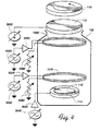
- Fig. 1 is a perspective, partial cross-sectional view of a plasma-generating chamber in accordance with an embodiment of the present invention.
- Fig. 2 is a partial cross-sectional view of the plasma-generating chamber of Fig. 1 shown installed in a vacuum chamber.
- Fig. 3 is a schematic diagram of the electrical interconnections to the plasma-generating chambers of Figs. 1-2.
- Fig. 4 is a schematic diagram of alternative electrical interconnections to the plasma-generating chambers of Figs. 1-2.
- Fig. 5 is a schematic cross-sectional view of a plasma-generating chamber in accordance with the embodiments of Figs. 1-4.
- Fig. 6 is a graph schematically depicting the magnitude of the axial magnetic field strength of the magnetic field configuration of Fig. 5.
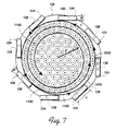
- Fig. 7 is a schematic, plan view from above of electron trajectories of the plasma-generating chambers in accordance with the embodiments of Figs. 1-4.
- a plasma generator in accordance with an embodiment of the present invention comprises a substantially cylindrical deposition system 100 which is received in a vacuum chamber 102 (shown schematically in Figure 3).
- the deposition system 100 of this embodiment has a chamber shield 106 that protects the interior walls 108 ( Figure 2) of the vacuum chamber 102 from the material being deposited within the interior of the deposition system 100.
- An ion flux strikes a negatively biased target 110 positioned at the top of the vacuum chamber 102.
- the target 110 is negatively biased by a DC power source 3000.
- the ions eject material from the target 110 onto a substrate 112 which may be a wafer or other workpiece which is supported by a pedestal 114 at the bottom of the deposition system 100.
- a rotating magnetron magnet assembly 116 provided above the target 110 produces magnetic fields which sweep over the face of the target 110 to promote uniform erosion of the target.
- energetic electrons are injected into the interior of the deposition system 100 by one or more electron guns 104 arranged tangentially around the periphery of the deposition system 100, energising a plasma 900 ( Figure 5) within the deposition system 100.
- the atoms of material ejected from the target 110 are, in turn, ionized by the electron cloud 900 such that the ionized deposition layer is attracted to the substrate 112 to form a deposition layer thereon.
- the pedestal 114 may be negatively biased by an AC (or DC or RF) source so as to externally bias the substrate 112.
- the electron guns 104 may be synchronised to inject the energetic electrons substantially continuously or in a pulsed manner. For example, using eight electron guns 104, each operating at an electron injection energy of about 20 keV and an electron current density of about 100 mAcm 2 , an electron density of about 5x10 12 cm 3 may be generated in the high density electron cloud 900. As explained in greater detail below, a magnetic field is used to confine the high density electron cloud 900. The magnetic field strength needed to generate such a high density electron cloud 900 may be about 50 Gauss or less.
- the operation pressure of the argon (Ar) gas may be reduced to less than or equal to about 5 ⁇ 10 -4 Torr (0.5 milliTorr or 500 microTorr). It is believed that a high density electron cloud 900, with an electron density of about 5 ⁇ 10 12 cm -3 , in an argon (Ar) gas, at an extremely low operation pressure of less than or equal to about 5 ⁇ 10 -4 Torr, may advantageously be used. More target material atoms may be ionized by the high density electron cloud 900 while fewer target material ions may be deflected by the extremely low pressure argon (Ar) gas.
- the electron guns 104 may have recessed windows 105 (shown in phantom) positioned a distance D from the end of the electron gun 104 exposed to the interior of deposition system 100. As shown, for example, in Fig. 2, the portion of the electron gun 104 exposed to the interior of deposition system 100 may pass through the wall 140 of the chamber shield 106 through a slot 107. The recessed windows 105 of the electron guns 104 allow the interior of the deposition system 100 to be maintained at a high vacuum.
- the distance D is chosen to be large enough (although necessarily less that the length L of the electron gun 104) so that window 105 is not plated over by the target material to be deposited on substrate 112 passing through the opening of the electron gun 104 having height H and width W (Figs. 1 and 2), with aspect ratios chosen so that D/H is preferably greater than or equal to about 5 and H/W is preferably greater than or equal to about 2.
- electron gun 104 is shown in Fig. 2 disposed on the interior of vacuum chamber wall 108, alternative embodiments may have one or more of the electron guns 104 extending outside of the vacuum chamber wall 108.
- Alternative sources for energetic electrons include "hot" filaments thermally emitting energetic electrons, and "cold” filaments using electron field emission, with "hot” emission being preferred using a tungsten or tantalum filament.
- the chamber shield 106 is magnetically shielded by magnetic fields generated by various types of magnets such as electromagnet coils 1000 and 1010 so as to minimize sputtering of material from the chamber shield 106.
- the deposition of target material onto the chamber shield 106 may also be reduced.
- contamination of the substrate 112 by material sputtered from the chamber shield 106 or by particulate matter shed by the chamber shield 106 may be reduced.
- Fig. 3 is a schematic representation of the electrical connections of the plasma generating apparatus of this illustrated embodiment.
- the target 110 is preferably negatively biased by a variable DC power source 3000.
- the pedestal 114 may be negatively biased by a variable DC power source 3010 to bias the substrate 112 negatively to attract the ionized deposition material to the substrate 112.
- the pedestal 114 may be biased by a high frequency RF power source to bias the substrate 112 so as to attract the ionized deposition material more uniformly to the substrate 112.
- the pedestal 114 is coupled to an RF source such as the output of an amplifier and matching network 3025, the input of which is coupled to an RF generator 3045.
- One end of the electromagnet coil 1000 may be coupled to a DC power source such as the output of a transformer and rectifying circuit 4020, the input of which is coupled to an AC power generator 4040.
- the other end of the electromagnet coil 1000 is coupled to ground, preferably through a resistor 4060, which may also be a variable resistor.
- one end of the electromagnet coil 1010 may be coupled to a DC power source such as the output of a transformer and rectifying circuit 5020, the input of which is coupled to an AC power generator 5040.
- the other end of the electromagnet coil 1010 is coupled to ground, preferably through a resistor 5060, which may also be a variable resistor.
- both electromagnet coils 1000 and 1010 may be identical, or both may be coupled to a common DC power generator, of course, or one or more DC power sources may be used.
- One or more of the electromagnet coils such as 1000 and 1010 may be superconducting, using windings of high-temperature or low-temperature superconducting materials, cryogenically cooled as needed, and able to be disconnected from any power supply once energized.
- Fig. 5 schematically represents the operation of the electromagnet coils 1000 and 1010 to reduce the sputtering of material from the chamber shield 106, and to reduce the generation of particulate matter by the chamber shield 106, and hence reduce contamination of the substrate 112.
- magnetic field lines 1100 are generated by the electromagnet coils 1000 and 1010, causing the energized electrons from the high density electron cloud 900 to spiral in helical paths 1200 around the magnetic field lines 1100, deflecting the energized electrons from impacting the chamber shield 106.
- the deflection of the energized electrons by the magnetic field lines 1100 also creates an electric field along the general direction of motion of the deflected electrons, deflecting energized ions of the high density electron cloud 900 and target material ions from impacting the chamber shield 106. Furthermore, the magnetic field lines 1100 are believed to squeeze the high density electron cloud 900 inward toward the central axis of the plasma chamber 100, creating a buffer region from a few mm up to a cm or more, depending on the strength of the magnetic field lines 1100, radially inward from the chamber shield 106, advantageously avoiding direct plasma heating of the chamber shield 106.
- the magnetic field lines 1100 can magnetically shield the chamber shield 106 to a limited extent from ionized deposition material which was originally ejected from the target 110. As a consequence, the accumulation of target material on the chamber shield 106 can be reduced, thereby reducing the formation of particulates that could subsequently dislodge from the chamber shield 106 and fall upon and contaminate the substrate 112.
- Typical magnetic field strengths generated by the electromagnet coils 1000 and 1010 in the region adjacent the chamber shield 106 may be in the range of 50-110 Gauss.
- Typical electron densities in the high density electron cloud 900 may be on the order of about 10 12 cm -3 to about 5 ⁇ 10 12 cm -3 .
- the operation pressure of the argon (Ar) gas may be less than or equal to about 5 ⁇ 10 -4 Torr (0.5 milliTorr or 500 microTorr).
- Fig. 6 schematically illustrates a preferred uniform arrangement for the magnitude of the magnetic field strength B z in the axial direction, plotted against the distance x from the central symmetry axis of the plasma chamber 100.
- the magnitude of the magnetic field strength a (Fig. 5) in the axial direction at the position x a closer to the central symmetry axis of the plasma chamber 100 is substantially the same as the magnitude of the magnetic field strength b (Fig. 5) in the axial direction at the position x b more distant from the central symmetry axis of the plasma chamber 100.
- the influence of the magnetic field lines 1100 on the central region of the high density electron cloud 900 may be undiminished in such a preferred uniform arrangement for the magnitude of the magnetic field strength B z in the axial direction, and a uniform plasma may be generated.
- Typical values for the magnitude of the magnetic field strength B z in the axial direction, at all distances x from the central symmetry axis of the plasma chamber 100, are on the order of 50 Gauss, as shown in Fig. 6, or less.
- Electromagnet coils 1000 and 1010 are positioned externally of the chamber shield 106, supported by electromagnet coil supports 1005 and 1015, respectively, as shown in Fig. 2. Electromagnet coil support 1005 may be attached to adapter ring assembly 152, and electromagnet coil support 1015 may be attached to vacuum chamber wall 108.
- the electromagnet coil 1000 connects, through an adapter ring assembly feedthrough (not shown), to a DC power source, as shown in Fig. 3.
- the electromagnet coil 1010 also connects, through a vacuum chamber wall feedthrough (not shown), to a DC power source, as shown in Fig. 3.
- one or both of the electromagnet coils 1000 and 1010 may be connected to an AC power source, which may cause the high density electron cloud 900 to rotate, which can lead to enhanced uniformity of deposition of material from the target 110 onto the substrate 112.
- Figs. 1-5 shows only two electromagnet coils 1000 and 1010 being used, but, of course as few as one electromagnet coil could be used, and as many as ten or more electromagnet coils could also be used, or a combination of electromagnet coils and permanent magnets could be used as well.
- An advantage of using more electromagnet coils is that more electromagnet coils enable more precise shaping or "bottling" of the high density electron cloud 900, which can increase the effective electron density of the high density electron cloud 900 and lead to enhanced uniformity of deposition of material from the target 110 onto the substrate 112, especially onto the fine features and structures of the substrate 112, particularly those with very high aspect ratios, such as deep, narrow trenches, vias and contact holes.
- Fig. 7 shows a schematic, plan view from above of electron trajectories of the deposition systems 100 in accordance with the embodiments of Figs. 1-5.
- magnetic field lines 1100 generated by electromagnet coils 1000 and 1010, as in the embodiments of Figs. 1-5, cause the energized electrons in the high density electron cloud 900 to cycle in spiral paths 1200 around the magnetic field lines 1100.
- the electron guns 104 are arranged to inject the energetic electrons substantially tangentially into the interior of chamber shield 106. Also as shown in Fig.
- an electron at radial (vector) distance r from the center of high density electron cloud 900 has a (vector) velocity v directed tangentially along the spiral path 1200.
- the spiral paths 1200 shown in Fig. 7 are appropriate for electrons since the magnetic field lines 1100 are coming out of the plane of the figure in Fig. 7.
- the radius r of the electron's orbit decreases as E 1 ⁇ 2 , spiraling inward toward a central region of the high density electron cloud 900 within the deposition system 100, as shown by the spiral path 1200 in Fig. 7. Electrons are believed to create ions by colliding with gas and/or metal atoms with sufficient energy. By magnetically trapping electrons, more ionizations are believed to occur.
- the chamber shield 106 protects the vacuum chamber walls 108 from the material being deposited.
- the chamber shield 106 is made of a conductive material such as heavy-duty, bead-blasted solid high-purity (preferably 99.995% pure) titanium formed into a generally cylindrical shape having a diameter of 25-36 cm (10-14 inches).
- a conductive material such as heavy-duty, bead-blasted solid high-purity (preferably 99.995% pure) titanium formed into a generally cylindrical shape having a diameter of 25-36 cm (10-14 inches).
- conductive material such as heavy-duty, bead-blasted solid high-purity (preferably 99.995% pure) titanium formed into a generally cylindrical shape having a diameter of 25-36 cm (10-14 inches).
- other highly conductive materials may be utilized depending upon the material being sputtered and other factors.
- the material of the structure which will be coated should have a coefficient of thermal expansion which closely matches that of the material being sputtered to reduce flaking of sputtered material from the shield or other chamber internal structure onto the wafer.
- the material to be coated should have good adhesion to the sputtered material.
- the deposited material is titanium
- the preferred metal of the shields, brackets and other structures likely to be coated is bead-blasted titanium. Any surfaces which are likely to sputter would preferably be made of the same type of material as the target such as high purity titanium, for example.
- the material to be deposited is a material other than titanium, the preferred metal is the deposited material, stainless steel or copper.
- Adherence can also be improved by coating the structures with molybdenum prior to sputtering the target.
- the coil or any other surface likely to sputter
- the coil not be coated with molybdenum or other materials since the molybdenum can contaminate the workpiece if sputtered from the coil.
- the chamber shield 106 is generally bowl-shaped (Fig. 2) and includes a generally cylindrically shaped, vertically oriented wall 140.
- the chamber shield 106 further has a generally annular-shaped floor wall 142 which surrounds the pedestal 114 which supports the substrate 112 which has a 20 cm (8") diameter in the illustrated embodiment.
- a clamp ring 154 may be used to clamp the substrate 112 to the pedestal 114 and cover the gap between the floor wall of the chamber shield 106 and the pedestal 114.
- the deposition system 100 is supported by an adapter ring assembly 152 which engages an upper annular flange 150 of the vacuum chamber wall 108.
- the outer shield 106 is grounded to the system ground through the adapter ring assembly 152.
- the darkspace shield 130 like the chamber shield 106, is grounded through the adapter ring assembly 152.
- the darkspace shield 130 also has an upper flange 170 which is fastened to the horizontal flange 162 of the adapter ring assembly 152.
- the darkspace shield 130 like the chamber shield 106, is grounded through the adapter ring assembly 152.
- the target 110 is generally disk-shaped and is also supported by the adapter ring assembly 152. However, the target 110 is negatively biased and therefore should be insulated from the adapter ring assembly 152 which is grounded. Accordingly, seated in a circular channel 176 formed in the underside of the target 110 is a ceramic insulation ring assembly 172 which is also seated in a corresponding channel 174 in the upper side of the adapter ring assembly 152.
- the insulator ring assembly 172 which may be made of a variety of insulative materials including ceramics spaces the target 110 from the adapter ring assembly 152 so that the target 110 may be adequately negatively biased.
- the target, adapter and ceramic ring assembly are provided with O-ring sealing surfaces 178 to provide a vacuum tight assembly from the vacuum chamber 102 to the target 110.
- a magnetron 116 (Fig. 2) may be provided above the target 110.
- the magnetron might be omitted by increasing the energetic electron injection ionization of the high density electron cloud 900.
- a DC power setting for biasing the target 110 of 3 kW is preferred but a range of 2-5 kW and a pedestal bias voltage of -30 volts DC is believed to be satisfactory for many applications.
- the substrate 112 to target 110 spacing is preferably about 140 mm but can range from about 8 cm to 20 cm (3" to 8").
- a chamber shield diameter of about 36 cm (14 inches) is preferred.
- gases may be utilized in the plasma chamber 100, including Ar, H 2 or reactive gases such as NF 3 , CF 4 and many others.
- gases include Ar, H 2 or reactive gases such as NF 3 , CF 4 and many others.
- gases include Ar, H 2 or reactive gases such as NF 3 , CF 4 and many others.
- Various gas pressures are suitable including pressures of about 0.1 milliTorr or less.
- a pressure less than or equal to about 5 ⁇ 10 -4 Torr (0.5 milliTorr or 500 microTorr) is suitable for ionization of sputtered material.
Landscapes
- Chemical & Material Sciences (AREA)
- Engineering & Computer Science (AREA)
- Physics & Mathematics (AREA)
- Plasma & Fusion (AREA)
- Analytical Chemistry (AREA)
- Materials Engineering (AREA)
- Organic Chemistry (AREA)
- Metallurgy (AREA)
- Mechanical Engineering (AREA)
- Chemical Kinetics & Catalysis (AREA)
- Power Engineering (AREA)
- Physical Vapour Deposition (AREA)
- Physical Deposition Of Substances That Are Components Of Semiconductor Devices (AREA)
- Plasma Technology (AREA)
Applications Claiming Priority (2)
| Application Number | Priority Date | Filing Date | Title |
|---|---|---|---|
| US08/812,657 US6599399B2 (en) | 1997-03-07 | 1997-03-07 | Sputtering method to generate ionized metal plasma using electron beams and magnetic field |
| US812657 | 1997-03-07 |
Publications (2)
| Publication Number | Publication Date |
|---|---|
| EP0869535A2 true EP0869535A2 (de) | 1998-10-07 |
| EP0869535A3 EP0869535A3 (de) | 2000-10-18 |
Family
ID=25210251
Family Applications (1)
| Application Number | Title | Priority Date | Filing Date |
|---|---|---|---|
| EP98301667A Withdrawn EP0869535A3 (de) | 1997-03-07 | 1998-03-06 | Verfahren zur Erzeugung ionisierter Metallplasma mittels Elektronenstrahlen und magnetischem Feldes |
Country Status (6)
| Country | Link |
|---|---|
| US (1) | US6599399B2 (de) |
| EP (1) | EP0869535A3 (de) |
| JP (1) | JPH10259477A (de) |
| KR (1) | KR19980080200A (de) |
| SG (1) | SG85597A1 (de) |
| TW (1) | TW386253B (de) |
Cited By (4)
| Publication number | Priority date | Publication date | Assignee | Title |
|---|---|---|---|---|
| WO2005118907A1 (en) * | 2004-05-26 | 2005-12-15 | Applied Materials, Inc. | Variable quadruple electromagnet array, particularly used in a multi-step process for forming a metal barrier in a sputter reactor |
| US7527713B2 (en) | 2004-05-26 | 2009-05-05 | Applied Materials, Inc. | Variable quadruple electromagnet array in plasma processing |
| CN101835334A (zh) * | 2010-01-19 | 2010-09-15 | 大连理工大学 | 一种交叉场放电共振耦合的控制方法 |
| DE19936199B4 (de) * | 1998-09-28 | 2013-01-24 | Alcatel Lucent | Magnetronreaktor zum Bereitstellen einer hochdichten, induktiv gekoppelten Plasmaquelle zum Sputtern von Metallfilmen und Dielektrischen Filmen |
Families Citing this family (34)
| Publication number | Priority date | Publication date | Assignee | Title |
|---|---|---|---|---|
| US10047430B2 (en) | 1999-10-08 | 2018-08-14 | Applied Materials, Inc. | Self-ionized and inductively-coupled plasma for sputtering and resputtering |
| US8696875B2 (en) * | 1999-10-08 | 2014-04-15 | Applied Materials, Inc. | Self-ionized and inductively-coupled plasma for sputtering and resputtering |
| JP3610289B2 (ja) * | 2000-04-28 | 2005-01-12 | キヤノン株式会社 | スパッタ装置及びスパッタ方法 |
| US8048806B2 (en) | 2000-03-17 | 2011-11-01 | Applied Materials, Inc. | Methods to avoid unstable plasma states during a process transition |
| US8617351B2 (en) | 2002-07-09 | 2013-12-31 | Applied Materials, Inc. | Plasma reactor with minimal D.C. coils for cusp, solenoid and mirror fields for plasma uniformity and device damage reduction |
| US6602381B1 (en) | 2001-04-30 | 2003-08-05 | Lam Research Corporation | Plasma confinement by use of preferred RF return path |
| US7374636B2 (en) * | 2001-07-06 | 2008-05-20 | Applied Materials, Inc. | Method and apparatus for providing uniform plasma in a magnetic field enhanced plasma reactor |
| JP4009087B2 (ja) * | 2001-07-06 | 2007-11-14 | アプライド マテリアルズ インコーポレイテッド | 半導体製造装置における磁気発生装置、半導体製造装置および磁場強度制御方法 |
| US7041201B2 (en) * | 2001-11-14 | 2006-05-09 | Applied Materials, Inc. | Sidewall magnet improving uniformity of inductively coupled plasma and shields used therewith |
| TWI283899B (en) * | 2002-07-09 | 2007-07-11 | Applied Materials Inc | Capacitively coupled plasma reactor with magnetic plasma control |
| US7504006B2 (en) | 2002-08-01 | 2009-03-17 | Applied Materials, Inc. | Self-ionized and capacitively-coupled plasma for sputtering and resputtering |
| US7458335B1 (en) | 2002-10-10 | 2008-12-02 | Applied Materials, Inc. | Uniform magnetically enhanced reactive ion etching using nested electromagnetic coils |
| US7422654B2 (en) * | 2003-02-14 | 2008-09-09 | Applied Materials, Inc. | Method and apparatus for shaping a magnetic field in a magnetic field-enhanced plasma reactor |
| DE10334962A1 (de) * | 2003-07-31 | 2005-03-03 | Vanier, Stéphane, Dr. | Rotativer Elektromagnet |
| USD529057S1 (en) * | 2004-08-16 | 2006-09-26 | Williams Advanced Materials, Inc. | Sputtering target |
| US7632375B2 (en) * | 2004-12-30 | 2009-12-15 | Lam Research Corporation | Electrically enhancing the confinement of plasma |
| EP1937865A4 (de) * | 2005-10-18 | 2012-12-12 | Southwest Res Inst | Ersosionsbeständige beschichtungen |
| US20090214787A1 (en) * | 2005-10-18 | 2009-08-27 | Southwest Research Institute | Erosion Resistant Coatings |
| US7981262B2 (en) * | 2007-01-29 | 2011-07-19 | Applied Materials, Inc. | Process kit for substrate processing chamber |
| US20090020415A1 (en) * | 2007-07-16 | 2009-01-22 | Michael Gutkin | "Iontron" ion beam deposition source and a method for sputter deposition of different layers using this source |
| JP5464800B2 (ja) * | 2007-11-19 | 2014-04-09 | 株式会社Jcu | スパッタリング装置及び成膜方法 |
| US8790791B2 (en) | 2010-04-15 | 2014-07-29 | Southwest Research Institute | Oxidation resistant nanocrystalline MCrAl(Y) coatings and methods of forming such coatings |
| US9511572B2 (en) | 2011-05-25 | 2016-12-06 | Southwest Research Institute | Nanocrystalline interlayer coating for increasing service life of thermal barrier coating on high temperature components |
| US20120048725A1 (en) * | 2011-06-24 | 2012-03-01 | Primestar Solar, Inc. | Non-bonded rotary semiconducting targets and methods of their sputtering |
| US9281231B2 (en) * | 2011-10-12 | 2016-03-08 | Ferrotec (Usa) Corporation | Non-contact magnetic drive assembly with mechanical stop elements |
| US9293303B2 (en) * | 2013-08-30 | 2016-03-22 | Taiwan Semiconductor Manufacturing Company, Ltd. | Low contamination chamber for surface activation |
| GB201505578D0 (en) * | 2015-03-31 | 2015-05-13 | Spts Technologies Ltd | Method and apparatus for depositing a material |
| US9523146B1 (en) | 2015-06-17 | 2016-12-20 | Southwest Research Institute | Ti—Si—C—N piston ring coatings |
| KR102037910B1 (ko) * | 2017-03-27 | 2019-10-30 | 세메스 주식회사 | 코팅 장치 및 코팅 방법 |
| TWI650046B (zh) * | 2017-07-24 | 2019-02-01 | 台灣積體電路製造股份有限公司 | 陰極結構及包含此陰極結構之離子化金屬電漿裝置 |
| JP6887688B2 (ja) * | 2019-02-07 | 2021-06-16 | 株式会社高純度化学研究所 | 蒸発原料用容器、及びその蒸発原料用容器を用いた固体気化供給システム |
| JP6901153B2 (ja) * | 2019-02-07 | 2021-07-14 | 株式会社高純度化学研究所 | 薄膜形成用金属ハロゲン化合物の固体気化供給システム。 |
| US11773484B2 (en) * | 2020-06-26 | 2023-10-03 | Tokyo Electron Limited | Hard mask deposition using direct current superimposed radio frequency plasma |
| CN114438463B (zh) * | 2022-01-25 | 2023-02-03 | 吉林大学 | 一种芯片真空镀膜装置及镀膜方法 |
Family Cites Families (71)
| Publication number | Priority date | Publication date | Assignee | Title |
|---|---|---|---|---|
| US4362632A (en) | 1974-08-02 | 1982-12-07 | Lfe Corporation | Gas discharge apparatus |
| US4336118A (en) * | 1980-03-21 | 1982-06-22 | Battelle Memorial Institute | Methods for making deposited films with improved microstructures |
| JPS5845892B2 (ja) * | 1980-06-23 | 1983-10-13 | 大阪真空化学株式会社 | スパツタ蒸着装置 |
| JPS59190363A (ja) | 1983-04-11 | 1984-10-29 | Orient Watch Co Ltd | 金属薄膜の形成方法 |
| FR2557149B1 (fr) | 1983-12-27 | 1989-11-17 | France Etat | Procede et dispositif pour le depot, sur un support, d'une couche mince d'un materiau a partir d'un plasma reactif |
| US4865712A (en) | 1984-05-17 | 1989-09-12 | Varian Associates, Inc. | Apparatus for manufacturing planarized aluminum films |
| US4661228A (en) | 1984-05-17 | 1987-04-28 | Varian Associates, Inc. | Apparatus and method for manufacturing planarized aluminum films |
| EP0169744A3 (de) | 1984-07-26 | 1987-06-10 | United Kingdom Atomic Energy Authority | Ionenquelle |
| JPH0740468B2 (ja) | 1984-12-11 | 1995-05-01 | 株式会社日立製作所 | 高周波プラズマ発生装置 |
| JPS61190070A (ja) | 1985-02-20 | 1986-08-23 | Hitachi Ltd | スパツタ装置 |
| JPS61238958A (ja) * | 1985-04-15 | 1986-10-24 | Hitachi Ltd | 複合薄膜形成法及び装置 |
| US4588490A (en) | 1985-05-22 | 1986-05-13 | International Business Machines Corporation | Hollow cathode enhanced magnetron sputter device |
| US4626312A (en) | 1985-06-24 | 1986-12-02 | The Perkin-Elmer Corporation | Plasma etching system for minimizing stray electrical discharges |
| GB8629634D0 (en) | 1986-12-11 | 1987-01-21 | Dobson C D | Reactive ion & sputter etching |
| DE3700633C2 (de) * | 1987-01-12 | 1997-02-20 | Reinar Dr Gruen | Verfahren und Vorrichtung zum schonenden Beschichten elektrisch leitender Gegenstände mittels Plasma |
| US4792732A (en) | 1987-06-12 | 1988-12-20 | United States Of America As Represented By The Secretary Of The Air Force | Radio frequency plasma generator |
| US5175608A (en) | 1987-06-30 | 1992-12-29 | Hitachi, Ltd. | Method of and apparatus for sputtering, and integrated circuit device |
| JP2602276B2 (ja) | 1987-06-30 | 1997-04-23 | 株式会社日立製作所 | スパツタリング方法とその装置 |
| KR920003789B1 (ko) | 1988-02-08 | 1992-05-14 | 니뽄 덴신 덴와 가부시끼가이샤 | 플라즈마 스퍼터링을 이용한 박막 형성 장치 및 이온원 |
| US4842703A (en) | 1988-02-23 | 1989-06-27 | Eaton Corporation | Magnetron cathode and method for sputter coating |
| DE3809734C1 (de) * | 1988-03-23 | 1989-05-03 | Helmut Prof. Dr. 7805 Boetzingen De Haberland | |
| JP2859632B2 (ja) | 1988-04-14 | 1999-02-17 | キヤノン株式会社 | 成膜装置及び成膜方法 |
| US4871421A (en) | 1988-09-15 | 1989-10-03 | Lam Research Corporation | Split-phase driver for plasma etch system |
| US4925542A (en) | 1988-12-08 | 1990-05-15 | Trw Inc. | Plasma plating apparatus and method |
| US4918031A (en) | 1988-12-28 | 1990-04-17 | American Telephone And Telegraph Company,At&T Bell Laboratories | Processes depending on plasma generation using a helical resonator |
| GB8905075D0 (en) | 1989-03-06 | 1989-04-19 | Nordiko Ltd | Electrode assembly and apparatus |
| US5135629A (en) | 1989-06-12 | 1992-08-04 | Nippon Mining Co., Ltd. | Thin film deposition system |
| US5421891A (en) | 1989-06-13 | 1995-06-06 | Plasma & Materials Technologies, Inc. | High density plasma deposition and etching apparatus |
| US5429070A (en) | 1989-06-13 | 1995-07-04 | Plasma & Materials Technologies, Inc. | High density plasma deposition and etching apparatus |
| US5091049A (en) | 1989-06-13 | 1992-02-25 | Plasma & Materials Technologies, Inc. | High density plasma deposition and etching apparatus |
| US5122251A (en) | 1989-06-13 | 1992-06-16 | Plasma & Materials Technologies, Inc. | High density plasma deposition and etching apparatus |
| US4990229A (en) | 1989-06-13 | 1991-02-05 | Plasma & Materials Technologies, Inc. | High density plasma deposition and etching apparatus |
| US5234560A (en) | 1989-08-14 | 1993-08-10 | Hauzer Holdings Bv | Method and device for sputtering of films |
| US4948458A (en) | 1989-08-14 | 1990-08-14 | Lam Research Corporation | Method and apparatus for producing magnetically-coupled planar plasma |
| JP2834797B2 (ja) | 1989-10-25 | 1998-12-14 | 株式会社リコー | 薄膜形成装置 |
| DE3942964A1 (de) | 1989-12-23 | 1991-06-27 | Leybold Ag | Einrichtung fuer die erzeugung eines plasmas |
| US5391275A (en) | 1990-03-02 | 1995-02-21 | Applied Materials, Inc. | Method for preparing a shield to reduce particles in a physical vapor deposition chamber |
| US5202008A (en) | 1990-03-02 | 1993-04-13 | Applied Materials, Inc. | Method for preparing a shield to reduce particles in a physical vapor deposition chamber |
| US5304279A (en) | 1990-08-10 | 1994-04-19 | International Business Machines Corporation | Radio frequency induction/multipole plasma processing tool |
| US5178739A (en) * | 1990-10-31 | 1993-01-12 | International Business Machines Corporation | Apparatus for depositing material into high aspect ratio holes |
| US5206516A (en) | 1991-04-29 | 1993-04-27 | International Business Machines Corporation | Low energy, steered ion beam deposition system having high current at low pressure |
| KR100255703B1 (ko) | 1991-06-27 | 2000-05-01 | 조셉 제이. 스위니 | 전자기 rf연결부를 사용하는 플라즈마 처리기 및 방법 |
| US5280154A (en) | 1992-01-30 | 1994-01-18 | International Business Machines Corporation | Radio frequency induction plasma processing system utilizing a uniform field coil |
| US5368685A (en) | 1992-03-24 | 1994-11-29 | Hitachi, Ltd. | Dry etching apparatus and method |
| US5361016A (en) | 1992-03-26 | 1994-11-01 | General Atomics | High density plasma formation using whistler mode excitation in a reduced cross-sectional area formation tube |
| US5225740A (en) | 1992-03-26 | 1993-07-06 | General Atomics | Method and apparatus for producing high density plasma using whistler mode excitation |
| US5231334A (en) | 1992-04-15 | 1993-07-27 | Texas Instruments Incorporated | Plasma source and method of manufacturing |
| US5241245A (en) | 1992-05-06 | 1993-08-31 | International Business Machines Corporation | Optimized helical resonator for plasma processing |
| US5397962A (en) | 1992-06-29 | 1995-03-14 | Texas Instruments Incorporated | Source and method for generating high-density plasma with inductive power coupling |
| JP3311387B2 (ja) | 1992-07-09 | 2002-08-05 | 株式会社不二越 | 複合スパッタリング装置 |
| JP3688726B2 (ja) | 1992-07-17 | 2005-08-31 | 株式会社東芝 | 半導体装置の製造方法 |
| US5404079A (en) | 1992-08-13 | 1995-04-04 | Matsushita Electric Industrial Co., Ltd. | Plasma generating apparatus |
| US5346600A (en) * | 1992-08-14 | 1994-09-13 | Hughes Aircraft Company | Plasma-enhanced magnetron-sputtered deposition of materials |
| US5312717A (en) | 1992-09-24 | 1994-05-17 | International Business Machines Corporation | Residue free vertical pattern transfer with top surface imaging resists |
| US5803977A (en) * | 1992-09-30 | 1998-09-08 | Applied Materials, Inc. | Apparatus for full wafer deposition |
| US5346578A (en) | 1992-11-04 | 1994-09-13 | Novellus Systems, Inc. | Induction plasma source |
| US5433812A (en) | 1993-01-19 | 1995-07-18 | International Business Machines Corporation | Apparatus for enhanced inductive coupling to plasmas with reduced sputter contamination |
| JP3224443B2 (ja) | 1993-02-08 | 2001-10-29 | 靖浩 堀池 | ヘリコン波プラズマ処理装置 |
| JP3271359B2 (ja) | 1993-02-25 | 2002-04-02 | ソニー株式会社 | ドライエッチング方法 |
| JP3252518B2 (ja) | 1993-03-19 | 2002-02-04 | ソニー株式会社 | ドライエッチング方法 |
| JP3174981B2 (ja) | 1993-03-26 | 2001-06-11 | 東京エレクトロン株式会社 | ヘリコン波プラズマ処理装置 |
| US5430355A (en) | 1993-07-30 | 1995-07-04 | Texas Instruments Incorporated | RF induction plasma source for plasma processing |
| US5418431A (en) | 1993-08-27 | 1995-05-23 | Hughes Aircraft Company | RF plasma source and antenna therefor |
| DE4430905C1 (de) | 1994-08-31 | 1995-05-24 | Metallgesellschaft Ag | Verfahren zur kontinuierlichen Herstellung von Bier |
| US5503676A (en) | 1994-09-19 | 1996-04-02 | Lam Research Corporation | Apparatus and method for magnetron in-situ cleaning of plasma reaction chamber |
| JPH07176399A (ja) | 1994-10-24 | 1995-07-14 | Tokyo Electron Ltd | プラズマ処理装置 |
| JP2657170B2 (ja) | 1994-10-24 | 1997-09-24 | 東京エレクトロン株式会社 | プラズマ処理装置 |
| JP3483327B2 (ja) | 1994-11-29 | 2004-01-06 | アネルバ株式会社 | プラズマ処理方法 |
| FR2732818B1 (fr) | 1995-04-07 | 1997-06-20 | Centre Nat Rech Scient | Procede et dispositif de controle de la polarisation d'un corps plonge dans un plasma |
| JPH08288259A (ja) | 1995-04-18 | 1996-11-01 | Sony Corp | ヘリコン波プラズマ装置およびこれを用いたドライエッチング方法 |
| US5573595A (en) | 1995-09-29 | 1996-11-12 | Lam Research Corporation | Methods and apparatus for generating plasma |
-
1997
- 1997-03-07 US US08/812,657 patent/US6599399B2/en not_active Expired - Fee Related
-
1998
- 1998-02-18 TW TW087102301A patent/TW386253B/zh not_active IP Right Cessation
- 1998-02-23 SG SG9800391A patent/SG85597A1/en unknown
- 1998-03-06 KR KR1019980008404A patent/KR19980080200A/ko not_active Withdrawn
- 1998-03-06 EP EP98301667A patent/EP0869535A3/de not_active Withdrawn
- 1998-03-09 JP JP10056955A patent/JPH10259477A/ja not_active Withdrawn
Cited By (8)
| Publication number | Priority date | Publication date | Assignee | Title |
|---|---|---|---|---|
| DE19936199B4 (de) * | 1998-09-28 | 2013-01-24 | Alcatel Lucent | Magnetronreaktor zum Bereitstellen einer hochdichten, induktiv gekoppelten Plasmaquelle zum Sputtern von Metallfilmen und Dielektrischen Filmen |
| WO2005118907A1 (en) * | 2004-05-26 | 2005-12-15 | Applied Materials, Inc. | Variable quadruple electromagnet array, particularly used in a multi-step process for forming a metal barrier in a sputter reactor |
| US7527713B2 (en) | 2004-05-26 | 2009-05-05 | Applied Materials, Inc. | Variable quadruple electromagnet array in plasma processing |
| KR100927275B1 (ko) * | 2004-05-26 | 2009-11-18 | 어플라이드 머티어리얼스, 인코포레이티드 | 전자석 코일 어레이와 그 조립체, 이들을 포함하는 플라즈마 프로세싱 반응기, 그 반응기의 작동 및 처리 방법 |
| EP1774054A4 (de) * | 2004-05-26 | 2010-01-27 | Applied Materials Inc | Variable quadrupelelektromagnetanordnung, die insbesondere bei einem mehrstufigen verfahren zur bildung einer metallbarriere in einem sputterreaktor verwendet wird |
| US7686926B2 (en) | 2004-05-26 | 2010-03-30 | Applied Materials, Inc. | Multi-step process for forming a metal barrier in a sputter reactor |
| CN101835334A (zh) * | 2010-01-19 | 2010-09-15 | 大连理工大学 | 一种交叉场放电共振耦合的控制方法 |
| CN101835334B (zh) * | 2010-01-19 | 2013-01-30 | 大连理工大学 | 一种交叉场放电共振耦合的控制方法 |
Also Published As
| Publication number | Publication date |
|---|---|
| EP0869535A3 (de) | 2000-10-18 |
| US6599399B2 (en) | 2003-07-29 |
| KR19980080200A (ko) | 1998-11-25 |
| TW386253B (en) | 2000-04-01 |
| SG85597A1 (en) | 2002-01-15 |
| US20020005348A1 (en) | 2002-01-17 |
| JPH10259477A (ja) | 1998-09-29 |
Similar Documents
| Publication | Publication Date | Title |
|---|---|---|
| US6599399B2 (en) | Sputtering method to generate ionized metal plasma using electron beams and magnetic field | |
| US6514390B1 (en) | Method to eliminate coil sputtering in an ICP source | |
| US6143140A (en) | Method and apparatus to improve the side wall and bottom coverage in IMP process by using magnetic field | |
| US6254737B1 (en) | Active shield for generating a plasma for sputtering | |
| US6238528B1 (en) | Plasma density modulator for improved plasma density uniformity and thickness uniformity in an ionized metal plasma source | |
| US5961793A (en) | Method of reducing generation of particulate matter in a sputtering chamber | |
| US5968327A (en) | Ionizing sputter device using a coil shield | |
| US6190513B1 (en) | Darkspace shield for improved RF transmission in inductively coupled plasma sources for sputter deposition | |
| EP1076911B1 (de) | Verfahren und vorrichtung zur ionisierten physikalischen dampfabscheidung | |
| US5948215A (en) | Method and apparatus for ionized sputtering | |
| JP3730867B2 (ja) | プラズマ蒸着法並びに磁気バケットおよび同心プラズマおよび材料源を備える装置 | |
| US6368469B1 (en) | Coils for generating a plasma and for sputtering | |
| KR19980033213A (ko) | 스퍼터링 챔버내의 미립자 물질 발생 감소 방법 | |
| US6660134B1 (en) | Feedthrough overlap coil | |
| WO1998048444A1 (en) | Method and apparatus for ionized sputtering of materials | |
| US6506287B1 (en) | Overlap design of one-turn coil | |
| US6103070A (en) | Powered shield source for high density plasma | |
| EP0836219A2 (de) | Aktive Abschirmung zur Erzeugung eines Plasmas für die Zerstäubung | |
| US6146508A (en) | Sputtering method and apparatus with small diameter RF coil | |
| EP0841683A2 (de) | Aktive Abschirmung zur Erzeugung eines Plasmas für die Zerstäubung | |
| WO2000003055A1 (en) | Shield for ionized physical vapor deposition apparatus | |
| KR930001231B1 (ko) | 다중극 자장억류 원리를 이용한 대용량 이온플레이팅 방법 및 그장치 | |
| Wendt | High-density plasma sources |
Legal Events
| Date | Code | Title | Description |
|---|---|---|---|
| PUAI | Public reference made under article 153(3) epc to a published international application that has entered the european phase |
Free format text: ORIGINAL CODE: 0009012 |
|
| AK | Designated contracting states |
Kind code of ref document: A2 Designated state(s): AT BE CH DE DK ES FI FR GB GR IE IT LI LU MC NL PT SE |
|
| PUAL | Search report despatched |
Free format text: ORIGINAL CODE: 0009013 |
|
| AK | Designated contracting states |
Kind code of ref document: A3 Designated state(s): AT BE CH DE DK ES FI FR GB GR IE IT LI LU MC NL PT SE |
|
| AX | Request for extension of the european patent |
Free format text: AL;LT;LV;MK;RO;SI |
|
| AKX | Designation fees paid | ||
| REG | Reference to a national code |
Ref country code: DE Ref legal event code: 8566 |
|
| STAA | Information on the status of an ep patent application or granted ep patent |
Free format text: STATUS: THE APPLICATION IS DEEMED TO BE WITHDRAWN |
|
| 18D | Application deemed to be withdrawn |
Effective date: 20010419 |