EP0870443A2 - Stuhl, insbesondere Bürostuhl - Google Patents
Stuhl, insbesondere Bürostuhl Download PDFInfo
- Publication number
- EP0870443A2 EP0870443A2 EP98105157A EP98105157A EP0870443A2 EP 0870443 A2 EP0870443 A2 EP 0870443A2 EP 98105157 A EP98105157 A EP 98105157A EP 98105157 A EP98105157 A EP 98105157A EP 0870443 A2 EP0870443 A2 EP 0870443A2
- Authority
- EP
- European Patent Office
- Prior art keywords
- chair
- seat support
- support
- seat
- backrest
- Prior art date
- Legal status (The legal status is an assumption and is not a legal conclusion. Google has not performed a legal analysis and makes no representation as to the accuracy of the status listed.)
- Withdrawn
Links
- 230000001360 synchronised effect Effects 0.000 claims description 9
- 230000037396 body weight Effects 0.000 claims description 8
- 230000001419 dependent effect Effects 0.000 claims description 4
- 230000035945 sensitivity Effects 0.000 claims description 3
- 210000002414 leg Anatomy 0.000 description 15
- 238000005452 bending Methods 0.000 description 3
- 230000007246 mechanism Effects 0.000 description 3
- 230000005540 biological transmission Effects 0.000 description 1
- 210000003127 knee Anatomy 0.000 description 1
Images

Classifications
-
- A—HUMAN NECESSITIES
- A47—FURNITURE; DOMESTIC ARTICLES OR APPLIANCES; COFFEE MILLS; SPICE MILLS; SUCTION CLEANERS IN GENERAL
- A47C—CHAIRS; SOFAS; BEDS
- A47C1/00—Chairs adapted for special purposes
- A47C1/02—Reclining or easy chairs
- A47C1/031—Reclining or easy chairs having coupled concurrently adjustable supporting parts
- A47C1/032—Reclining or easy chairs having coupled concurrently adjustable supporting parts the parts being movably-coupled seat and back-rest
- A47C1/03255—Reclining or easy chairs having coupled concurrently adjustable supporting parts the parts being movably-coupled seat and back-rest with a central column, e.g. rocking office chairs
-
- A—HUMAN NECESSITIES
- A47—FURNITURE; DOMESTIC ARTICLES OR APPLIANCES; COFFEE MILLS; SPICE MILLS; SUCTION CLEANERS IN GENERAL
- A47C—CHAIRS; SOFAS; BEDS
- A47C1/00—Chairs adapted for special purposes
- A47C1/02—Reclining or easy chairs
- A47C1/031—Reclining or easy chairs having coupled concurrently adjustable supporting parts
- A47C1/032—Reclining or easy chairs having coupled concurrently adjustable supporting parts the parts being movably-coupled seat and back-rest
- A47C1/03261—Reclining or easy chairs having coupled concurrently adjustable supporting parts the parts being movably-coupled seat and back-rest characterised by elastic means
- A47C1/03266—Reclining or easy chairs having coupled concurrently adjustable supporting parts the parts being movably-coupled seat and back-rest characterised by elastic means with adjustable elasticity
-
- A—HUMAN NECESSITIES
- A47—FURNITURE; DOMESTIC ARTICLES OR APPLIANCES; COFFEE MILLS; SPICE MILLS; SUCTION CLEANERS IN GENERAL
- A47C—CHAIRS; SOFAS; BEDS
- A47C1/00—Chairs adapted for special purposes
- A47C1/02—Reclining or easy chairs
- A47C1/031—Reclining or easy chairs having coupled concurrently adjustable supporting parts
- A47C1/032—Reclining or easy chairs having coupled concurrently adjustable supporting parts the parts being movably-coupled seat and back-rest
- A47C1/03261—Reclining or easy chairs having coupled concurrently adjustable supporting parts the parts being movably-coupled seat and back-rest characterised by elastic means
- A47C1/03277—Reclining or easy chairs having coupled concurrently adjustable supporting parts the parts being movably-coupled seat and back-rest characterised by elastic means with bar or leaf springs
Definitions
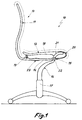
- the invention relates to a chair, in particular an office chair, with a seat bracket that can be tilted in relation to the horizontal and one in sync with the inclination of the seat support in his Adjustable backrest support.
- the present invention has for its object a Chair with a synchronous adjustment mechanism of the seat and to create the backrest that is less constructive than the solutions known since then.
- the task is carried out with a chair of the type mentioned at the beginning solved according to the invention in that the seat support and Backrest support made of an elastic at least in some areas resilient component are formed and the seat support an essentially U-shaped area of the component consists of one of the legs of the U-shaped seat support is arranged on a chair column.
- the seat support and backrest support are omitted assembly work required for conventional chairs.
- the Entire chair consists of a few individual components that are quick can be assembled. Due to the U-shaped design of the seat support this gets the necessary flexibility.
- the legs of the U-shaped seat support in their end region coupled to one another via a connecting element.
- the connecting element can be elastic, so that an unimpeded but controlled transmission of the movement of the Seat support on the backrest support is possible.
- the leading edge the base of the U-shaped part forming the seat of the chair Seat carrier can advantageously be flexible and on a guideway connected to the chair column be led. This is a lowering of the seat possible to the rear without changing the height of the front edge The seat changes, causing an uncomfortable pressure on the would lead the user's legs in the area of the hollow of the knees.
- the leg of the U-shaped Seat carrier can also be pivoted to a limited extent about a horizontal axis be arranged on the chair column.
- the seat support and the backrest support can be pivoted forward on the chair column to support the Back of the user even when the work posture is bent forward to support well.
- the inclination of the seat support and the backrest support can also be locked will.
- Devices for body weight-dependent adjustment of the Sensitivity of the synchronous adjustment on the backrest and Seat support can be arranged.
- the Stiffness of the leg of the Seat carrier by means of a slidable along the leg Sleeve can be adjusted depending on body weight. By moving the sleeve becomes the bending zone of the leg in length varies and thus the stiffness of the leg is adjusted.
- the chair can also lock the tilt of the seat and backrest support. Also the The depth of the seat can be adjusted.
- the seat support 12 has a backrest support 11 on, which is formed in one piece with a seat support 12. That forming the backrest support 11 and the seat support 12 Component 13 is bent in a U-shape in the area of the seat support 12.
- One leg 14 of the U-shaped seat support 12 is over a Bearing 15 connected to a chair column 16, which is in a base 17 is arranged adjustable in height.
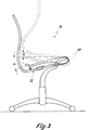
- the leg 14 of the U-shaped seat support 12 is over with the second leg 18 a connecting element 19 is elastically connected.
- the seat support 12 has a flexible Zone 20 on. In this area the seat support 12 is on an arcuate guide track 21, which with the Chair column 16 is connected.
- the leg 14 of the seat support 12 mounted on a lockable axis 22 on the chair column 16, which also allows pivoting of the seat support 12 to the front.
- the two most extreme inclination positions of the chair 10 are shown in Fig. 3.
- the seat support 12 is one Angle ⁇ can be lowered below the horizontal 30 and by an angle ⁇ can be raised relative to the horizontal 30.
- the seat support 12 forms the seat support 12 with the Backrest support 11 has an angle ⁇ which is greater than that Angle ⁇ between the seat support 12 and the backrest support 11 in the rest position of the seat support 12, as shown in FIG. 2.
- the front edge 20 of the chair 10 changes its height when Do not lower the seat support 12 below the horizontal 30.
- the different inclinations of the seat and backrest support can be locked by means of a clamping device 31 will.
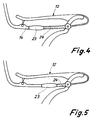
- the synchronous adjustment depending on the body weight of the The user of the chair is the leg 14 of the U-shaped seat support 12 provided with a sleeve 23, which is along the leg 14 is displaceable (Fig. 4, 5). Is the sleeve 23, as in Fig. 4 shown pushed as far back as possible the bending area 24 of the leg 14 has its greatest extent.
- the synchronous adjustment requires only a small amount Effort.
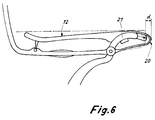
- Fig. 6 shows a seat support 12 with a Possibility of seat depth adjustment. Because of the flexible Area 20 on the front edge of the seat support 12 can be the depth of the seat support 12 by, for example, a telescopic Extension of the guideway 21 by a maximum of Increase amount d.
Landscapes
- Health & Medical Sciences (AREA)
- Dentistry (AREA)
- General Health & Medical Sciences (AREA)
- Chairs Characterized By Structure (AREA)
- Special Chairs (AREA)
Abstract
Description
- Fig. 1
- eine schematische Seitenansicht eines erfindungsgemäßen Stuhles;
- Fig. 2
- eine vergrößerte Detailansicht des Sitzträgers und des Rückenlehnenträgers nach Fig. 1 in zwei unterschiedlichen Neigungsstellungen;
- Fig. 3
- eine Seitenansicht des Stuhles nach Fig. 1 in den beiden Neigungsendpositionen der Rückenlehne und des Sitzträgers;
- Fig. 4
- eine Detailansicht des Sitzträgers des Stuhles nach Fig. 1 mit einem Element zur körpergewichtsabhängigen Empfindlichkeitseinstellung in einer ersten Position;
- Fig. 5
- eine der Fig. 4 entsprechende Ansicht mit dem Einstellelement in einer zweiten Position;
- Fig. 6
- eine vergrößerte Detailansicht des Sitzträgers des Stuhles mit einer Sitztiefenverstelleinrichtung.
Claims (10)
- Stuhl, insbesondere Bürostuhl, mit einem gegenüber der Horizontalen (30) neigbaren Sitzträger (12) und einem synchron zur Neigung des Sitzträgers (12) in seiner Neigung verstellbaren Rückenlehnenträger (11), dadurch gekennzeichnet, daß der Sitzträger (12) und der Rückenlehnenträger (11) aus einem mindestens bereichsweise elastisch federnden Bauteil (13) gebildet sind und der Sitzträger (12) aus einem im wesentlichen U-förmig gebogenen Bereich des Bauteiles (13) besteht, wobei einer der Schenkel (14) des U-förmigen Sitzträgers (12) an einer Stuhlsäule (16) angeordnet ist.
- Stuhl nach Anspruch 1, dadurch gekennzeichnet, daß die Schenkel (14, 18) des U-förmigen Sitzträgers (12) in ihrem Endbereich über ein Verbindungselement (19) miteinander gekoppelt sind.
- Stuhl nach Anspruch 1 oder 2, dadurch gekennzeichnet, daß die die Vorderkante (20) der Sitzfläche des Stuhles (10) bildende Basis des U-förmigen Sitzträgers (12) flexibel ausgebildet und an einer mit der Stuhlsäule (16) verbundenen Führungsbahn (21) geführt ist.
- Stuhl nach einem der Ansprüche 1 bis 3, dadurch gekennzeichnet, daß der Sitzträger (12) und der Rückenlehnenträger (11) begrenzt nach vorne verschwenkbar an der Stuhlsäule (16) angeordnet sind.
- Stuhl nach Anspruch 4, dadurch gekennzeichnet, daß der Schenkel (14) des U-förmigen Sitzträgers (12) um eine horizontale Achse begrenzt verschwenkbar an der Stuhlsäule (16) angeordnet ist.
- Stuhl nach einem der Ansprüche 1 bis 5, dadurch gekennzeichnet, daß Vorrichtungen (23) zur körpergewichtsabhängigen Einstellung der Empfindlichkeit der Synchronverstellung von Rückenlehne (11) und Sitzträger (12) vorgesehen sind.
- Stuhl nach Anspruch 6, dadurch gekennzeichnet, daß die Steifigkeit des an der Stuhlsäule (16) angeordneten Schenkels (14) des Sitzträgers (12) mittels einer entlang des Schenkels (14) verschiebbaren Hülse (23) körpergewichtsabhängig einstellbar ist.
- Stuhl nach einem der Ansprüche 1 bis 7, dadurch gekennzeichnet, daß das Bauteil (13) für den Sitzträger (12) und den Rückenlehnenträger (11) aus Kunststoff besteht.
- Stuhl nach einem der Ansprüche 1 bis 8, dadurch gekennzeichnet, daß er Vorrichtungen zur Arretierung der Neigung des Sitz- und des Rückenlehnenträgers aufweist.
- Stuhl nach einem der Ansprüche 1 bis 9, dadurch gekennzeichnet, daß die Tiefe der Sitzfläche verstellbar ist.
Applications Claiming Priority (2)
| Application Number | Priority Date | Filing Date | Title |
|---|---|---|---|
| DE19714546A DE19714546A1 (de) | 1997-04-09 | 1997-04-09 | Stuhl, insbesondere Bürostuhl |
| DE19714546 | 1997-04-09 |
Publications (2)
| Publication Number | Publication Date |
|---|---|
| EP0870443A2 true EP0870443A2 (de) | 1998-10-14 |
| EP0870443A3 EP0870443A3 (de) | 2000-02-23 |
Family
ID=7825835
Family Applications (1)
| Application Number | Title | Priority Date | Filing Date |
|---|---|---|---|
| EP98105157A Withdrawn EP0870443A3 (de) | 1997-04-09 | 1998-03-21 | Stuhl, insbesondere Bürostuhl |
Country Status (2)
| Country | Link |
|---|---|
| EP (1) | EP0870443A3 (de) |
| DE (1) | DE19714546A1 (de) |
Cited By (9)
| Publication number | Priority date | Publication date | Assignee | Title |
|---|---|---|---|---|
| WO2001076418A1 (en) * | 2000-03-31 | 2001-10-18 | Cazzaro S.P.A. | Chair |
| EP1230876A1 (de) * | 2001-02-12 | 2002-08-14 | Interstuhl Büromöbel GmbH & Co. KG | Sitzmöbel |
| US10966527B2 (en) | 2017-06-09 | 2021-04-06 | Steelcase Inc. | Seating arrangement and method of construction |
| US11096497B2 (en) | 2015-04-13 | 2021-08-24 | Steelcase Inc. | Seating arrangement |
| US11109683B2 (en) | 2019-02-21 | 2021-09-07 | Steelcase Inc. | Body support assembly and method for the use and assembly thereof |
| US11259637B2 (en) | 2015-04-13 | 2022-03-01 | Steelcase Inc. | Seating arrangement |
| US11324325B2 (en) | 2015-04-13 | 2022-05-10 | Steelcase Inc. | Seating arrangement |
| US11357329B2 (en) | 2019-12-13 | 2022-06-14 | Steelcase Inc. | Body support assembly and methods for the use and assembly thereof |
| EP4616763A1 (de) * | 2024-03-15 | 2025-09-17 | Cerantola S.P.A. | Stuhl zum sitzen eines benutzers |
Families Citing this family (2)
| Publication number | Priority date | Publication date | Assignee | Title |
|---|---|---|---|---|
| US11617444B2 (en) | 2020-03-02 | 2023-04-04 | Steelcase Inc. | Body support assembly and methods for the use and assembly thereof |
| US11812870B2 (en) | 2021-02-10 | 2023-11-14 | Steelcase Inc. | Body support structure |
Family Cites Families (4)
| Publication number | Priority date | Publication date | Assignee | Title |
|---|---|---|---|---|
| DE3642796A1 (de) * | 1986-12-15 | 1988-06-23 | Eckhard Hansen | Punktsynchronverstelleinrichtung fuer buerostuehle, sitzmoebel o. dgl. |
| US4790596A (en) * | 1987-06-26 | 1988-12-13 | Shifferaw Tessema D | Resilient chair |
| US4889385A (en) * | 1988-03-09 | 1989-12-26 | American Seating Company | Chair seat-and-back support |
| DE4410383C2 (de) * | 1994-03-25 | 1996-07-25 | Desanta | Stuhl |
-
1997
- 1997-04-09 DE DE19714546A patent/DE19714546A1/de not_active Withdrawn
-
1998
- 1998-03-21 EP EP98105157A patent/EP0870443A3/de not_active Withdrawn
Non-Patent Citations (1)
| Title |
|---|
| None |
Cited By (19)
| Publication number | Priority date | Publication date | Assignee | Title |
|---|---|---|---|---|
| WO2001076418A1 (en) * | 2000-03-31 | 2001-10-18 | Cazzaro S.P.A. | Chair |
| EP1230876A1 (de) * | 2001-02-12 | 2002-08-14 | Interstuhl Büromöbel GmbH & Co. KG | Sitzmöbel |
| US11553797B2 (en) | 2015-04-13 | 2023-01-17 | Steelcase Inc. | Seating arrangement |
| US11963621B2 (en) | 2015-04-13 | 2024-04-23 | Steelcase Inc. | Seating arrangement |
| US11096497B2 (en) | 2015-04-13 | 2021-08-24 | Steelcase Inc. | Seating arrangement |
| US11259637B2 (en) | 2015-04-13 | 2022-03-01 | Steelcase Inc. | Seating arrangement |
| US11324325B2 (en) | 2015-04-13 | 2022-05-10 | Steelcase Inc. | Seating arrangement |
| US11825955B2 (en) | 2017-06-09 | 2023-11-28 | Steelcase Inc. | Seating arrangement and method of construction |
| US10966527B2 (en) | 2017-06-09 | 2021-04-06 | Steelcase Inc. | Seating arrangement and method of construction |
| US12582234B2 (en) | 2017-06-09 | 2026-03-24 | Steelcase Inc. | Seating arrangement |
| US11602223B2 (en) | 2019-02-21 | 2023-03-14 | Steelcase Inc. | Body support assembly and methods for the use and assembly thereof |
| US11109683B2 (en) | 2019-02-21 | 2021-09-07 | Steelcase Inc. | Body support assembly and method for the use and assembly thereof |
| US11910934B2 (en) | 2019-02-21 | 2024-02-27 | Steelcase Inc. | Body support assembly and methods for the use and assembly thereof |
| US12226025B2 (en) | 2019-02-21 | 2025-02-18 | Steelcase Inc. | Body support assembly and methods for the use and assembly thereof |
| US11357329B2 (en) | 2019-12-13 | 2022-06-14 | Steelcase Inc. | Body support assembly and methods for the use and assembly thereof |
| US11786039B2 (en) | 2019-12-13 | 2023-10-17 | Steelcase Inc. | Body support assembly and methods for the use and assembly thereof |
| US11805913B2 (en) | 2019-12-13 | 2023-11-07 | Steelcase Inc. | Body support assembly and methods for the use and assembly thereof |
| US12161232B2 (en) | 2019-12-13 | 2024-12-10 | Steelcase Inc. | Body support assembly and methods for the use and assembly thereof |
| EP4616763A1 (de) * | 2024-03-15 | 2025-09-17 | Cerantola S.P.A. | Stuhl zum sitzen eines benutzers |
Also Published As
| Publication number | Publication date |
|---|---|
| EP0870443A3 (de) | 2000-02-23 |
| DE19714546A1 (de) | 1998-10-15 |
Similar Documents
| Publication | Publication Date | Title |
|---|---|---|
| DE3744365C3 (de) | Stuhl, insbesondere Arbeits- oder Bürostuhl | |
| EP0399251B1 (de) | Stuhl, insbesondere Arbeits- oder Bürostuhl | |
| DE19930922B4 (de) | Stuhl | |
| WO2001091614A1 (de) | Stuhl | |
| EP0343450B1 (de) | Stuhl, insbesondere Arbeits- oder Bürostuhl | |
| DE3930983A1 (de) | Sitzmoebel mit neigungsverstellbarer sitzflaeche | |
| DE8560028U1 (de) | Stuhl, insbesondere Bürostuhl. | |
| EP0397661B1 (de) | Stuhl, insbesondere arbeits- oder bürostuhl | |
| DE3329581A1 (de) | Sitzmoebel mit synchroner rueckenlehnen- und sitzflaechenbewegung | |
| EP0870443A2 (de) | Stuhl, insbesondere Bürostuhl | |
| DE3642796A1 (de) | Punktsynchronverstelleinrichtung fuer buerostuehle, sitzmoebel o. dgl. | |
| DE3903388A1 (de) | Vorrichtung zum umwandeln eines buerostuhls in einen kniestuhl | |
| DE68918921T2 (de) | Verbesserungen an Stühlen. | |
| DE2000172B2 (de) | Stuhl, insbesondere arbeitsstuhl | |
| DE8808022U1 (de) | Stuhl, insbesondere Bürostuhl | |
| DE19502485C2 (de) | Stuhl | |
| DE3838999C2 (de) | ||
| DE8806835U1 (de) | Stuhl, insbesondere Arbeits- oder Bürostuhl | |
| DE2709960A1 (de) | Sitzmoebel, insbesondere drehbarer arbeitsstuhl | |
| EP0332088B1 (de) | Stuhl, insbesondere Arbeits und Bürostuhl | |
| DE3619928A1 (de) | Funktions-sitzmoebel | |
| DE102016011221B4 (de) | Hartschalenstuhl | |
| DE19608696C2 (de) | In ein Stehpult wandelbarer Stuhl | |
| DE10009264A1 (de) | Stuhl mit Sitz, Rücken und Sitzträger bildender federnder Schale | |
| DE29516840U1 (de) | Rückstellvorrichtung für einen Stuhl |
Legal Events
| Date | Code | Title | Description |
|---|---|---|---|
| PUAI | Public reference made under article 153(3) epc to a published international application that has entered the european phase |
Free format text: ORIGINAL CODE: 0009012 |
|
| AK | Designated contracting states |
Kind code of ref document: A2 Designated state(s): AT BE CH DE DK ES FI FR GB GR IE IT LI LU MC NL PT SE |
|
| AX | Request for extension of the european patent |
Free format text: AL;LT;LV;MK;RO;SI |
|
| PUAL | Search report despatched |
Free format text: ORIGINAL CODE: 0009013 |
|
| AK | Designated contracting states |
Kind code of ref document: A3 Designated state(s): AT BE CH DE DK ES FI FR GB GR IE IT LI LU MC NL PT SE |
|
| AX | Request for extension of the european patent |
Free format text: AL;LT;LV;MK;RO;SI |
|
| RIC1 | Information provided on ipc code assigned before grant |
Free format text: 7A 47C 1/032 A, 7A 47C 3/021 B |
|
| AKX | Designation fees paid | ||
| STAA | Information on the status of an ep patent application or granted ep patent |
Free format text: STATUS: THE APPLICATION IS DEEMED TO BE WITHDRAWN |
|
| 18D | Application deemed to be withdrawn |
Effective date: 20001003 |
|
| REG | Reference to a national code |
Ref country code: DE Ref legal event code: 8566 |