EP0870568A1 - Méthode et appareil pour le soudage de bandes - Google Patents
Méthode et appareil pour le soudage de bandes Download PDFInfo
- Publication number
- EP0870568A1 EP0870568A1 EP98106702A EP98106702A EP0870568A1 EP 0870568 A1 EP0870568 A1 EP 0870568A1 EP 98106702 A EP98106702 A EP 98106702A EP 98106702 A EP98106702 A EP 98106702A EP 0870568 A1 EP0870568 A1 EP 0870568A1
- Authority
- EP
- European Patent Office
- Prior art keywords
- mold
- strip
- fixture
- molds
- set forth
- Prior art date
- Legal status (The legal status is an assumption and is not a legal conclusion. Google has not performed a legal analysis and makes no representation as to the accuracy of the status listed.)
- Granted
Links
- 238000000034 method Methods 0.000 title claims abstract description 12
- 239000002184 metal Substances 0.000 claims description 16
- 238000003466 welding Methods 0.000 claims description 10
- 238000005266 casting Methods 0.000 claims 1
- 239000004020 conductor Substances 0.000 abstract description 8
- 239000000463 material Substances 0.000 description 7
- 239000000843 powder Substances 0.000 description 2
- 239000002893 slag Substances 0.000 description 2
- OKTJSMMVPCPJKN-UHFFFAOYSA-N Carbon Chemical compound [C] OKTJSMMVPCPJKN-UHFFFAOYSA-N 0.000 description 1
- 230000000994 depressogenic effect Effects 0.000 description 1
- 229910002804 graphite Inorganic materials 0.000 description 1
- 239000010439 graphite Substances 0.000 description 1
- 238000012856 packing Methods 0.000 description 1
- 239000011819 refractory material Substances 0.000 description 1
- 238000000926 separation method Methods 0.000 description 1
- 238000004904 shortening Methods 0.000 description 1
- 210000003813 thumb Anatomy 0.000 description 1
Images


Classifications
-
- B—PERFORMING OPERATIONS; TRANSPORTING
- B23—MACHINE TOOLS; METAL-WORKING NOT OTHERWISE PROVIDED FOR
- B23K—SOLDERING OR UNSOLDERING; WELDING; CLADDING OR PLATING BY SOLDERING OR WELDING; CUTTING BY APPLYING HEAT LOCALLY, e.g. FLAME CUTTING; WORKING BY LASER BEAM
- B23K23/00—Alumino-thermic welding
-
- B—PERFORMING OPERATIONS; TRANSPORTING
- B23—MACHINE TOOLS; METAL-WORKING NOT OTHERWISE PROVIDED FOR
- B23K—SOLDERING OR UNSOLDERING; WELDING; CLADDING OR PLATING BY SOLDERING OR WELDING; CUTTING BY APPLYING HEAT LOCALLY, e.g. FLAME CUTTING; WORKING BY LASER BEAM
- B23K2101/00—Articles made by soldering, welding or cutting
- B23K2101/36—Electric or electronic devices
- B23K2101/38—Conductors
Definitions
- This invention relates generally as indicated to a strip welder and method and more particularly to an exothermic welding apparatus for welding generally flat objects such as electrical conductors in the form of strip, braid, bars, tape, and the like, and a process for economically forming good high ampacity low resistance electrical connections for such objects.
- Exothermic welding has become recognized as a preferred way to form top quality high ampacity low resistance electrical connections.
- Reusable refractory molds usually made of graphite or the like are widely used with exothermic welding materials to make a wide variety of such high ampacity low resistance electrical connections.
- Typical of such molds are those sold under the well known trademark CADWELD® by ERICO International of Solon, Ohio USA.
- the reusable molds are two or more part molds usually opened and closed and held together by toggle clamps.
- the mold parts have faces which abut at a parting plane in which are formed recesses forming the various cavities and passages when the parts are clamped together.
- the mold parts form a weld chamber, which usually includes a riser which may be the enlarged lower end of a tap hole passage which extends from the top of the mold to the weld chamber.
- the parts to be welded enter the weld chamber through sleeving passages which extend from outside the mold to the weld chamber.
- Such passages usually extend horizontally or from the bottom.
- Horizontal passages are typically employed when welding conductor-to-conductor. They may be used in combination with a vertical passage when welding conductors to an earthing rod, for example.
- a crucible normally sits on top of the assembled mold parts.
- the crucible includes a chamber holding the exothermic material on top of a fusible disk.
- a sprue or tap hole below the disk communicates with the top of the tap hole of the mold.
- Such molds can be rather intricate and are not insignificant in cost. More importantly, for each type of connection a different mold assembly is normally required. This creates an extremely large number or inventory of molds, and makes the storage, transportation, and selective use of such molds both costly and burdensome. While some mold sets may accommodate different size conductors, usually with shims, sleeving or packing around smaller conductors in larger passages, such shims or sleeving contribute to the wear of the molds shortening their useful lives. All of the above contributes to the cost of making such high quality connections. Because of such costs, users and owners may select less expensive but less efficient connections, and connections of lower quality.
- a strip welder utilizes relatively few mold parts each having a clamping face to weld flat conductors such as conductive strip, bar, braids or even tape.
- One mold part includes a tap hole leading to a weld chamber, and some such tap hole molds may include shallow channels in the clamping face.
- a counter-mold part includes a chamber in the parting face and strip channels which accommodate the strip to be welded when the mold parts are clamped together.
- the counter-mold part has a generally square face and is supported in a fixture so that it can be turned 90° to form different types of connections.
- the counter mold may have an opposite face to make yet further types or sizes of connections.
- the molds are supported in a fixture which releasably secures the molds for quick interchangability.
- the molds may be oriented easily for making horizontal or vertical connections.
- the fixture includes a slightly angled crucible support for a vertical orientation weld.
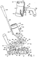
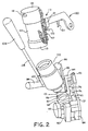
- the strip welder of the present invention is shown generally at 30 and includes a mold part 31 and a counter-mold part 32 which are supported by fixture 33.
- the fixture is shown partially open with the mold part 31 separated from the mold part 32 providing an opening or separation between the mold parts seen at 35 allowing the parts to be welded to be inserted in the proper position before the fixture closes the molds on each other and the parts to be welded.
- the mold 31 is shown in detail in Figure 6 and will be described later.
- the counter-mold 32 may have a variety of configurations and several forms are shown in Figures 7, 10 and 11.
- the molds are supported by the fixture which is illustrated in more detail in Figures 3 and 4, and the fixture, with additional reference to such Figures, will be described initially.
- the fixture includes a base 37.
- the base 37 is in the form of a plate which includes an enlarged end 38 having a generally octagonal external configuration, which end includes a central hole 39.
- the opposite end of the base plate is generally U-shape having two spaced legs 40 and 41. Pivoted between such legs at 43 is the down turned end 44 of a pivot support 45.
- the pivot support 45 includes a midsection 46 provided with an elongated hole 47, and an upturned end 48.
- the midsection 46 is generally at right angles to the down turned pivot end section 44 and the upturned outer end 48.
- a plate 50 Secured to the top of the upturned outer end is a plate 50 which is provided with an almost complete circular hole 51.
- the hole 51 extends for somewhat more than 270° and is aligned with the hole 39.
- the plate 51 includes tapped holes 53 and 54 which are diametrically positioned with respect to the hole 51. While most of the profile edges of the plate seen in Figure 3 are normal to the plane of such Figure, the plate does include edges near the support 48 seen at 56 which are inclined at about 20° to the axis of the hole 51.
- a crucible support indicated at 58 is mounted on one of those surfaces by a suitable fastener 59.
- the crucible support is a generally rectangular plate having a canter enlarged hole 61 which supports the crucible when a vertical orientation weld is being made. This use of the crucible support will be described later.
- each bracket includes triangular upstanding corner posts seen at 68 and 69, and each is secured to the base plate by a fastener 70 extending through the reduced height center portion 71.
- the bracket 63 is provided with a set screw 72 seen in Figure 1 which is designed to clamp the mold 32 within the confines of brackets. It is noted that the brackets are arranged to provide a generally square enclosure for the generally square counter-mold 32, and that the flat edges of the mold each extend at about 45° to the pivot access or hinge 43.
- the strip passing diagonally between the clamp faces of the molds 31 and 32 clears the hinge area of the fixture.
- the elevated triangular posts not only confine the mold, but provide the edges of guide slots for the strip.
- the depressed center portions which provide clearance for the strip, but also enable an installer to remove and replace a counter-mold quite easily, even with a gloved hand.
- a stop post 74 which extends through a hole 75 in the base plate and is adjustably clamped in place by set screw 76.
- the top of the stop post is designed to engage the heel of the hinge support as seen at 77 in Figure 4. This adjustably limits the shut height of the fixture.
- a shoulder stud 79 Extending upwardly from the base next to the stop post 74 is a shoulder stud 79 which includes a reduced diameter upper portion 80 to which is secured locking head 81.
- Extending upwardly from the intermediate portion 46 of the hinged support is a handle 83 having a grip 84.
- the handle 83 also serves as a pivot for a lever 85 having a knob grip 86 on the outer end.
- the inner end is provided with a hook 88 adapted to swing beneath the head 81 of the locking stud 79 as seen in the full line positions of Figures 3 and 4.
- the locking stud head projects through the hole 47 when the upper pivoting support is in the shut or closed position seen in Figure 4. Moving the handle to the full line position seen will lock the fixture closed.
- the open position is shown in phantom lines at 89.
- the upper mold 31 which is also shown in detail in Figure 6 includes a cylindrical neck 90 which includes diametrically opposed recesses 91 and 92. These recesses accommodate the studs of shoulder bolts 93 seen in Figure 1 which are threaded in the diametrically opposed holes 53 and 54. In this manner the mold 31 is secured to the hinged portion of the fixture, and the bolts provide a slight gimbal pivot for the upper mold enabling it to adjust slightly to ensure that it is properly pressed against the counter-mold and any strip or other objects to be welded therebetween.
- the mold 31 also includes a tap hole 95 which extends from a circular seat 96 into the rectangular portion 97 of the mold 31 which contains a riser chamber 98 and a weld chamber 99.
- the tap hole seat accommodates the nozzle 101 of crucible assembly 102.
- the crucible assembly is a refractory chamber formed in two half-round blocks of refractory material indicated at 103, one of which is held in half-round frame 104 by fastener 105.
- the opposite crucible part is held in a similar half-round frame which is locked to the stud 106 when closed. Both frames and crucible sections are hinged 107 to handle stud 108 which includes a grip 109.
- the exothermic material When a weld is to be made, the exothermic material is inserted into the top of the crucible and into the crucible chamber on top of a metal disk which is seated at the bottom of the crucible chamber over the tap hole of the crucible. A starting powder may be inserted on top of the exothermic material.
- the exothermic material when ready to use, is then ignited by the igniter assembly seen at 112 in Figures 1 and 2.
- the igniter includes a cylindrical container 113 which has a bell-mouth bottom 115 designed to telescope over the top of the crucible.
- the igniter includes a removable lid 116 which may be attached to the chamber 113 by the chain 117.
- the lid includes a vent opening 118 directed away from the installer.
- a flint gun shown at 120 is secured in collar 121 projecting from the container 113 by the thumb screw 122.
- the trigger 123 When the trigger 123 is actuated, a spark is generated within the container 113 which then ignites the starting powder and the exothermic material within the crucible. The exothermic reaction fuses the disk permitting the molten metal formed to run downwardly through the nozzle 101 and into the assembled molds.
- Figure 5 illustrates a half or tap hole mold 125 which can be used by itself to make a weld connection such as seen in Figure 12.
- the mold 125 includes a tap hole 126 having at one end a crucible seat 127.
- the tap hole extends to an enlarged dome-like chamber 128 which opens to the bottom of the mold at the mold clamp face 129.
- the clamp face includes a laterally extending recess channel 130 designed to accommodate a strip 131 such as seen in Figure 12.
- the mold 125 may be used by itself secured in the hinged portion of the fixture, and clamped against a metal plate 132.
- the weld metal mass 133 is formed by the chamber 128.
- the connection seen in Figure 12 is known as a CG connection. If the metal plate 132 is relatively thin, it may be supported or hacked up by a refractory block in the base of the fixture.
- Figure 6 illustrates the half mold 31 shown in the fixture in 31.
- the lower rectangular portion 97 which includes the weld chamber 99 has aligned shallow recess channels 134 and 135 in the clamping face 136 on opposite sides of the chamber 99.
- the counter-mold 32 seen in Figure 7 includes a clamping face 138 in which is formed a weld chamber recess 139 opposite the recess or chamber 99 in the half mold. Opposite shallow grooves or channels seen at 140 relieve the clamping face and accommodate strip to be welded. In Figure 7 the channels 140 extend perpendicular to the plane of the page while the channels 134 and 135 extend parallel to such plane. It can be seen that by turning the counter-mold 32 90° the mold set 31 and 32 will form four different types of connection both crossing and in-line. For example, the mold set will form connections EB, EN, BN and BG. These four connections are seen at 142, 143, 144 and 145 in Figures 13-16 respectfully. In Figure 16 the counter-mold has been turned 90° from the mold in Figures 13, 14 and 15. The matching chambers form the weld metal mass 146 in each weld providing a good high ampacity low resistance connection between the two strips.
- a single mold illustrated in Figure 8 at 149 is employed.
- the mold includes a vertical clamp face 150 in which is formed the weld recess 151.
- the recess is in communication with inclined tap hole 152 leading to inclined crucible seat 153.
- the inclined crucible seat is inclined at about 20° from horizontal which is the approximate inclination of the crucible support 58 on the upper hinged support of the fixture.
- a channel recess 154 is provided in the clamping face 150 which may accommodate a strip 155 in the connection to plate 156.
- the weld mass 157 is formed by the chamber 151.
- Figure 9 illustrates a half mold 161 which generally corresponds to the mold 31 but which is adapted for vertical orientation connections.
- the mold 161 includes the diametrically opposed holes 162 and 163 to receive the fasteners 93 in the hinged support.
- the clamping face 164 is provided with the weld recess 165 which is in communication with channels 166.
- the square upper portion on the mold is cut away as indicated at 167 to provide an inclined opening 168.
- the crucible may be supported on the inclined crucible support to direct the molten metal into the opening 167.
- the inclined crucible support may be mounted on either side as seen in comparing Figures 1 and 2.
- the opposite or counter-mold used with the half mold of Figure 9, may be the same counter-mold 32 seen in Figure 7.
- the mold has, however, been turned for a vertical orientation and includes the chamber 39 in the clamp face 130 with the strip accommodating recesses 140.
- the counter-mold 32 may be turned 90° to form a variety of connections.
- the mold set of Figures 9 and 10 may form an ED, an EE, a DE, a BQ, a BF and a BJ connection. Some of these connections are seen in Figures 18, 19 and 20.
- the weld connection 170 seen in Figure 18 may be an ED type connection with the weld mass 146 being essentially the same as in the horizontal connections of Figure 13-16.
- the strips illustrated cross and overlap between the clamping faces of the mold.
- connection 171 seen in Figure 19 may, for example, be a BQ connection, while the connection 172 seen in Figure 22 may be a BF connection.
- a single mold set will make up to six different connections in a vertical orientation.
- FIG 11 there is illustrated a counter-mold 178 which is somewhat thicker than the counter-mold seen in Figures 7 and 10.
- the counter-mold 178 has opposite clamping faces 179 and 180 in which are formed weld recesses 182 and 183, respectively.
- the shallow grooves 184 and 185 in such faces may be a different size enabling the counter-mold to be turned both 90° and to be flipped over face-to-face to form different types of strip or braid connections, for example.
- certain types of connections may be made with a single counter-mold, either horizontally or vertically, or aligned or crossing as seen in comparing the various connections made.
- the high ampacity low resistance electrical connections between strip, bar, braid or other flat conductors can readily be made both vertically and horizontally and with relatively few simple molds.
- the counter-mold is simply repositioned 90° and vice versa whether vertical or horizontal. The invention not only reduces the number of mold sets required, but provides ease of handling and application.
Landscapes
- Engineering & Computer Science (AREA)
- Mechanical Engineering (AREA)
- Molds, Cores, And Manufacturing Methods Thereof (AREA)
Applications Claiming Priority (2)
| Application Number | Priority Date | Filing Date | Title |
|---|---|---|---|
| US4329697P | 1997-04-11 | 1997-04-11 | |
| US43296P | 1997-04-11 |
Publications (2)
| Publication Number | Publication Date |
|---|---|
| EP0870568A1 true EP0870568A1 (fr) | 1998-10-14 |
| EP0870568B1 EP0870568B1 (fr) | 2003-07-02 |
Family
ID=21926448
Family Applications (1)
| Application Number | Title | Priority Date | Filing Date |
|---|---|---|---|
| EP98106702A Expired - Lifetime EP0870568B1 (fr) | 1997-04-11 | 1998-04-14 | Méthode et appareil pour le soudage de bandes |
Country Status (2)
| Country | Link |
|---|---|
| EP (1) | EP0870568B1 (fr) |
| DE (1) | DE69815918T2 (fr) |
Cited By (6)
| Publication number | Priority date | Publication date | Assignee | Title |
|---|---|---|---|---|
| US6382496B1 (en) * | 2000-07-27 | 2002-05-07 | Harger, Inc. | Welding handle clamp |
| CN103894730A (zh) * | 2014-03-20 | 2014-07-02 | 南京唐模电气科技有限公司 | 模块组合式放热焊接模具 |
| CN107030373A (zh) * | 2017-06-09 | 2017-08-11 | 秉岳电气(上海)有限公司 | 一种用于放热焊的新型模具及焊接方法 |
| WO2019178405A1 (fr) * | 2018-03-14 | 2019-09-19 | Erico International Corporation | Moule de soudage modulaire |
| US10738999B2 (en) | 2017-10-03 | 2020-08-11 | Hubbell Incorporated | Trigger devices for exothermix welds |
| US11229970B2 (en) | 2017-08-21 | 2022-01-25 | Hubbell Incorporated | Handle for exothermic mold with spring connectors |
Citations (3)
| Publication number | Priority date | Publication date | Assignee | Title |
|---|---|---|---|---|
| DE1169763B (de) * | 1961-07-31 | 1964-05-06 | Erico Prod Inc | Vorrichtung zum exothermischen Schweissen |
| US3189959A (en) * | 1963-10-08 | 1965-06-22 | Elektro Thermit Gmbh | Aluminothermic welding of rails |
| EP0526362A1 (fr) * | 1991-08-02 | 1993-02-03 | Erico International Corporation | Procédé pour braser in situ un élément métallique sur un support métallique et dispositif pour sa mise en oeuvre |
-
1998
- 1998-04-14 EP EP98106702A patent/EP0870568B1/fr not_active Expired - Lifetime
- 1998-04-14 DE DE69815918T patent/DE69815918T2/de not_active Expired - Fee Related
Patent Citations (3)
| Publication number | Priority date | Publication date | Assignee | Title |
|---|---|---|---|---|
| DE1169763B (de) * | 1961-07-31 | 1964-05-06 | Erico Prod Inc | Vorrichtung zum exothermischen Schweissen |
| US3189959A (en) * | 1963-10-08 | 1965-06-22 | Elektro Thermit Gmbh | Aluminothermic welding of rails |
| EP0526362A1 (fr) * | 1991-08-02 | 1993-02-03 | Erico International Corporation | Procédé pour braser in situ un élément métallique sur un support métallique et dispositif pour sa mise en oeuvre |
Cited By (9)
| Publication number | Priority date | Publication date | Assignee | Title |
|---|---|---|---|---|
| US6382496B1 (en) * | 2000-07-27 | 2002-05-07 | Harger, Inc. | Welding handle clamp |
| CN103894730A (zh) * | 2014-03-20 | 2014-07-02 | 南京唐模电气科技有限公司 | 模块组合式放热焊接模具 |
| CN107030373A (zh) * | 2017-06-09 | 2017-08-11 | 秉岳电气(上海)有限公司 | 一种用于放热焊的新型模具及焊接方法 |
| US11229970B2 (en) | 2017-08-21 | 2022-01-25 | Hubbell Incorporated | Handle for exothermic mold with spring connectors |
| US11724327B2 (en) | 2017-08-21 | 2023-08-15 | Hubbell Incorporated | Handle for exothermic mold with spring connectors |
| US10738999B2 (en) | 2017-10-03 | 2020-08-11 | Hubbell Incorporated | Trigger devices for exothermix welds |
| US10935239B2 (en) | 2017-10-03 | 2021-03-02 | Hubbell Incorporated | Trigger devices for exothermic welds |
| US11441776B2 (en) | 2017-10-03 | 2022-09-13 | Hubbell Incorporated | Trigger devices for exothermic welds |
| WO2019178405A1 (fr) * | 2018-03-14 | 2019-09-19 | Erico International Corporation | Moule de soudage modulaire |
Also Published As
| Publication number | Publication date |
|---|---|
| DE69815918T2 (de) | 2004-06-03 |
| DE69815918D1 (de) | 2003-08-07 |
| EP0870568B1 (fr) | 2003-07-02 |
Similar Documents
| Publication | Publication Date | Title |
|---|---|---|
| EP1273381B1 (fr) | Appareil de soudage et procédé pour réaliser des connexions électriques | |
| US5954261A (en) | Welding mold and method | |
| US5715886A (en) | Single use welding mold and method | |
| US6382496B1 (en) | Welding handle clamp | |
| US4119137A (en) | Automated post burn station | |
| EP0870568B1 (fr) | Méthode et appareil pour le soudage de bandes | |
| US5533662A (en) | Exothermic welding apparatus | |
| US5653279A (en) | Apparatus and method for forming electrical connections | |
| US20190001431A1 (en) | Configurable exothermic reaction mold | |
| US5829510A (en) | Exothermic welding crucible and method | |
| JP3215868B2 (ja) | 浸漬ノズルの交換装置 | |
| CA1088175A (fr) | Cosse de cable et methode de fabrication | |
| JP2002028792A (ja) | 熱溶接における改善 | |
| US5279455A (en) | Method of attaching a metal element to a metal supporting surface by brazing and apparatus for its implementation | |
| CH497932A (de) | Vorrichtung zum Beheizen von Blockköpfen und Speisern von Giessformen | |
| US3980126A (en) | Automated post burn station | |
| US4050501A (en) | Method of fusing a metal battery terminal post with a metal bushing | |
| US3554270A (en) | Metal casing apparatus and method | |
| US2401048A (en) | Rail bonding apparatus | |
| EP0870569B1 (fr) | Méthode et appareil de soudage | |
| AU750071B2 (en) | Mould comprising outer mould parts and moulding material cores inserted into same | |
| 殷树言 et al. | Mathematical model and magnetic-control mechanism of the stability of rotating spray transfer | |
| US3954216A (en) | Apparatus for thermal relay welding | |
| US5423521A (en) | Ceramic plug gas distribution device | |
| JPH0622748B2 (ja) | 溶湯注出方法及び摺動ゲート弁 |
Legal Events
| Date | Code | Title | Description |
|---|---|---|---|
| PUAI | Public reference made under article 153(3) epc to a published international application that has entered the european phase |
Free format text: ORIGINAL CODE: 0009012 |
|
| AK | Designated contracting states |
Kind code of ref document: A1 Designated state(s): DE ES FR GB IT NL |
|
| AX | Request for extension of the european patent |
Free format text: AL;LT;LV;MK;RO;SI |
|
| 17P | Request for examination filed |
Effective date: 19990318 |
|
| AKX | Designation fees paid |
Free format text: DE ES FR GB IT NL |
|
| 17Q | First examination report despatched |
Effective date: 20020712 |
|
| GRAH | Despatch of communication of intention to grant a patent |
Free format text: ORIGINAL CODE: EPIDOS IGRA |
|
| GRAH | Despatch of communication of intention to grant a patent |
Free format text: ORIGINAL CODE: EPIDOS IGRA |
|
| GRAA | (expected) grant |
Free format text: ORIGINAL CODE: 0009210 |
|
| AK | Designated contracting states |
Designated state(s): DE ES FR GB IT NL |
|
| PG25 | Lapsed in a contracting state [announced via postgrant information from national office to epo] |
Ref country code: IT Free format text: LAPSE BECAUSE OF FAILURE TO SUBMIT A TRANSLATION OF THE DESCRIPTION OR TO PAY THE FEE WITHIN THE PRESCRIBED TIME-LIMIT;WARNING: LAPSES OF ITALIAN PATENTS WITH EFFECTIVE DATE BEFORE 2007 MAY HAVE OCCURRED AT ANY TIME BEFORE 2007. THE CORRECT EFFECTIVE DATE MAY BE DIFFERENT FROM THE ONE RECORDED. Effective date: 20030702 Ref country code: ES Free format text: LAPSE BECAUSE OF FAILURE TO SUBMIT A TRANSLATION OF THE DESCRIPTION OR TO PAY THE FEE WITHIN THE PRESCRIBED TIME-LIMIT Effective date: 20030702 |
|
| REG | Reference to a national code |
Ref country code: GB Ref legal event code: FG4D |
|
| REF | Corresponds to: |
Ref document number: 69815918 Country of ref document: DE Date of ref document: 20030807 Kind code of ref document: P |
|
| ET | Fr: translation filed | ||
| PLBE | No opposition filed within time limit |
Free format text: ORIGINAL CODE: 0009261 |
|
| STAA | Information on the status of an ep patent application or granted ep patent |
Free format text: STATUS: NO OPPOSITION FILED WITHIN TIME LIMIT |
|
| 26N | No opposition filed |
Effective date: 20040405 |
|
| PGFP | Annual fee paid to national office [announced via postgrant information from national office to epo] |
Ref country code: FR Payment date: 20060313 Year of fee payment: 9 |
|
| PGFP | Annual fee paid to national office [announced via postgrant information from national office to epo] |
Ref country code: NL Payment date: 20060315 Year of fee payment: 9 |
|
| PGFP | Annual fee paid to national office [announced via postgrant information from national office to epo] |
Ref country code: DE Payment date: 20060317 Year of fee payment: 9 |
|
| GBPC | Gb: european patent ceased through non-payment of renewal fee |
Effective date: 20070414 |
|
| NLV4 | Nl: lapsed or anulled due to non-payment of the annual fee |
Effective date: 20071101 |
|
| PG25 | Lapsed in a contracting state [announced via postgrant information from national office to epo] |
Ref country code: NL Free format text: LAPSE BECAUSE OF NON-PAYMENT OF DUE FEES Effective date: 20071101 Ref country code: DE Free format text: LAPSE BECAUSE OF NON-PAYMENT OF DUE FEES Effective date: 20071101 |
|
| PG25 | Lapsed in a contracting state [announced via postgrant information from national office to epo] |
Ref country code: GB Free format text: LAPSE BECAUSE OF NON-PAYMENT OF DUE FEES Effective date: 20070414 |
|
| PG25 | Lapsed in a contracting state [announced via postgrant information from national office to epo] |
Ref country code: FR Free format text: LAPSE BECAUSE OF NON-PAYMENT OF DUE FEES Effective date: 20070430 |
|
| PGFP | Annual fee paid to national office [announced via postgrant information from national office to epo] |
Ref country code: GB Payment date: 20060316 Year of fee payment: 9 |