EP0870736B1 - Ofen und Verfahren zum Ziehen eines Stabs aus einer Glasvorform - Google Patents
Ofen und Verfahren zum Ziehen eines Stabs aus einer Glasvorform Download PDFInfo
- Publication number
- EP0870736B1 EP0870736B1 EP98106453A EP98106453A EP0870736B1 EP 0870736 B1 EP0870736 B1 EP 0870736B1 EP 98106453 A EP98106453 A EP 98106453A EP 98106453 A EP98106453 A EP 98106453A EP 0870736 B1 EP0870736 B1 EP 0870736B1
- Authority
- EP
- European Patent Office
- Prior art keywords
- glass preform
- furnace body
- elongating
- hole
- furnace
- Prior art date
- Legal status (The legal status is an assumption and is not a legal conclusion. Google has not performed a legal analysis and makes no representation as to the accuracy of the status listed.)
- Expired - Lifetime
Links
- 239000011521 glass Substances 0.000 title claims description 83
- 238000000034 method Methods 0.000 title claims description 15
- 238000010438 heat treatment Methods 0.000 claims description 11
- 239000012212 insulator Substances 0.000 claims description 7
- 230000001678 irradiating effect Effects 0.000 claims description 2
- 230000000149 penetrating effect Effects 0.000 claims 1
- 230000002093 peripheral effect Effects 0.000 claims 1
- 239000000463 material Substances 0.000 description 4
- 238000011144 upstream manufacturing Methods 0.000 description 4
- 238000001816 cooling Methods 0.000 description 3
- 239000000470 constituent Substances 0.000 description 2
- 230000006866 deterioration Effects 0.000 description 2
- 239000013307 optical fiber Substances 0.000 description 2
- 230000003647 oxidation Effects 0.000 description 2
- 238000007254 oxidation reaction Methods 0.000 description 2
- 230000004323 axial length Effects 0.000 description 1
- 238000005452 bending Methods 0.000 description 1
- 230000007423 decrease Effects 0.000 description 1
- 230000003247 decreasing effect Effects 0.000 description 1
- 230000001419 dependent effect Effects 0.000 description 1
- 230000000694 effects Effects 0.000 description 1
- 238000009413 insulation Methods 0.000 description 1
- 238000005259 measurement Methods 0.000 description 1
- 238000012986 modification Methods 0.000 description 1
- 230000004048 modification Effects 0.000 description 1
- 230000003287 optical effect Effects 0.000 description 1
- 230000000087 stabilizing effect Effects 0.000 description 1
Images




Classifications
-
- C—CHEMISTRY; METALLURGY
- C03—GLASS; MINERAL OR SLAG WOOL
- C03B—MANUFACTURE, SHAPING, OR SUPPLEMENTARY PROCESSES
- C03B37/00—Manufacture or treatment of flakes, fibres, or filaments from softened glass, minerals, or slags
- C03B37/01—Manufacture of glass fibres or filaments
- C03B37/012—Manufacture of preforms for drawing fibres or filaments
- C03B37/01205—Manufacture of preforms for drawing fibres or filaments starting from tubes, rods, fibres or filaments
- C03B37/01225—Means for changing or stabilising the shape, e.g. diameter, of tubes or rods in general, e.g. collapsing
- C03B37/0124—Means for reducing the diameter of rods or tubes by drawing, e.g. for preform draw-down
-
- C—CHEMISTRY; METALLURGY
- C03—GLASS; MINERAL OR SLAG WOOL
- C03B—MANUFACTURE, SHAPING, OR SUPPLEMENTARY PROCESSES
- C03B23/00—Re-forming shaped glass
- C03B23/04—Re-forming tubes or rods
- C03B23/043—Heating devices specially adapted for re-forming tubes or rods in general, e.g. burners
-
- C—CHEMISTRY; METALLURGY
- C03—GLASS; MINERAL OR SLAG WOOL
- C03B—MANUFACTURE, SHAPING, OR SUPPLEMENTARY PROCESSES
- C03B23/00—Re-forming shaped glass
- C03B23/04—Re-forming tubes or rods
- C03B23/047—Re-forming tubes or rods by drawing
-
- C—CHEMISTRY; METALLURGY
- C03—GLASS; MINERAL OR SLAG WOOL
- C03B—MANUFACTURE, SHAPING, OR SUPPLEMENTARY PROCESSES
- C03B37/00—Manufacture or treatment of flakes, fibres, or filaments from softened glass, minerals, or slags
- C03B37/01—Manufacture of glass fibres or filaments
- C03B37/012—Manufacture of preforms for drawing fibres or filaments
- C03B37/01205—Manufacture of preforms for drawing fibres or filaments starting from tubes, rods, fibres or filaments
- C03B37/01225—Means for changing or stabilising the shape, e.g. diameter, of tubes or rods in general, e.g. collapsing
- C03B37/01257—Heating devices therefor
Definitions
- the present invention relates to an elongating apparatus and method for a glass preform, and a furnace body for the elongating apparatus.
- it relates to an elongating apparatus or the like for performing precise elongating for making optical fibers and the like.
- JP-A-08 091 861 discloses a furnace body having the features which are recited in the preamble of claim 1.
- Fig. 6 is an overall schematic view of a vertical resistance furnace elongating apparatus of the same type as the apparatus mentioned above, whereas Figs. 7 and 8 are respectively schematic and sectional views showing the configuration of its furnace body portion.
- dummy rods 41 and 42 are respectively attached to both ends of a glass preform 4, and the latter passes through a furnace core tube 11 (see Figs. 7 and 8) within the furnace body 1 while its parts corresponding to the dummy rods 41 and 42 are respectively held by an upper chuck 7 and a lower chuck 8.
- the furnace body 1 has a four-layer structure in which, successively from the inside, the furnace core tube 11, a heater 12, a thermal insulator 13, and a furnace body outer shell 14 are disposed.
- a taper portion 6, which is a boundary between the glass preform 4 and the elongated body 5, is preferably positioned within the furnace body 1 and more preferably positioned within the furnace core tube 11 shown in Fig. 7.
- the heated glass will yield differences in viscosity distribution within its transverse cross section.
- the distribution of amount of expansion in the axial direction of the glass preform becomes uneven in the transverse cross section, whereby the elongated body may bend or distort its form.
- the outer diameter distribution of the elongated body in the axial direction may become uneven.
- Japanese Patent Application Laid-Open No. 56-45843 discloses a technique for keeping the outer diameter of such an elongated body constant in its axial direction (hereinafter simply referred to as "conventional control technique").
- This technique performs feedback control such that the outer diameter of the taper portion of the glass preform while being elongated is measured, and the moving speeds of the upper and lower chucks are changed according to thus measured value, so as to keep the outer diameter of the taper portion constant, thereby maintaining a constant outer diameter of the elongated body in the axial direction.
- the inventor has found that, when the above-mentioned control technique is used for obtaining an elongated body with a desired uniform outer diameter, setting the position for measuring the outer diameter of the taper portion used for feedback control is important.
- the outer diameter measuring position is disposed near the upper end of the taper portion, i.e., near the heater; even when the moving speeds of the chucks are controlled to keep the outer diameter of the upper end of the taper portion constant, the outer diameter may be varied at the taper portion, thereby the outer diameter of the elongated body may become uneven and fluctuation.
- the outer diameter measuring position is disposed near the lower end of the taper portion; since the glass preform has almost been cooled at this position and its viscosity has been quite large to be elongated, even if a fluctuation in the outer diameter is detected, it can hardly be corrected.
- Japanese Patent Application Laid-Open No. 56-45843 discloses an example in which an exposed glass preform is directly heated by a burner so as to be processed. In such a case, since the taper portion is exposed, the outer diameter measuring position can be altered easily. However, since it is hard to control cooling of the glass preform, this technique is not easily applicable to cases elongating a glass preform and forming a thin elongated body.
- the taper portion as a whole is typically accommodated in the furnace body. Consequently, the outer diameter of the taper portion is hard to measure.
- the present invention provides a furnace body having the features which are recited in claim 1.
- the invention also provides an elongating apparatus comprising a furnace body according to claim 1 and having the features which are recited in claim 4, and further a method of elongating a glass preform using a furnace body according to claim 1 as recited in claim 5.
- the taper portion of the glass preform is disposed at the level of the through hole. Accordingly, via the through hole, the outer diameter of the taper portion can be measured by various kinds of non-contact type measuring methods. Also, since the taper portion of the glass preform is basically covered with the furnace core tube, the glass preform can be prevented from rapidly cooling down. Consequently, an elongating body having a uniform outer diameter can be made easily.
- a light-transmittable window material is attached to each of both ends of the through hole from outside so as to seal the through hole.
- the outer diameter of the taper portion can be measured in a non-contact fashion by use of light, the air is prevented from unnecessarily intruding into the furnace core tube from the through hole, whereby the heat distribution within the furnace core tube can be stabilized. And deterioration of the furnace body by unexpected oxidation of oxidizable material such as involving carbons can be prevented.
- the furnace body may further comprise a heat insulating member which is inserted into parts of the furnace body outer shell and thermal insulator corresponding to the through hole and has a slit in parallel to a transverse cross section of the furnace core tube orthogonal to the center axis thereof. This configuration is effective in further stabilizing the heat distribution within the furnace core tube.
- the elongating apparatus for a glass preform in accordance with the present invention employs this furnace body. Namely, it comprises the furnace body; supply means for supplying the glass preform into the furnace body; elongating means for elongating the glass preform from the furnace body; a light source, disposed outside one end of the through hole of the furnace body, for irradiating a light beam to the glass preform within the furnace core tube through the through hole so as to scan the glass preform transversely; a photodetector, disposed outside the other end of the through hole, for detecting the light beam emitted through the through hole; and control means for computing an outer diameter of the passing glass preform according to an output signal of the photodetector and controlling respective supplying and elongating speeds of the supplying and elongating means so as to keep the outer diameter constant.
- the method of elongating a glass preform in accordance with the present invention using the above-mentioned furnace body comprises the steps which are recited in claim 5.
- upstream and downstream refer to directions defined along the moving direction of a glass preform.
- downstream end of a heater indicates the end of the heater on the outlet side of the glass preform. It corresponds to the lower end of the heater when the glass preform moves from the upper side to the lower side.
- Fig. 1 is a schematic view of a glass preform elongating apparatus in accordance with the present invention. While the basic configuration of this apparatus is identical to that of the conventional vertical resistance furnace elongating apparatus shown in Fig. 6, this basic configuration will be explained here again.
- this elongating apparatus is an apparatus for elongating a glass preform 4 by stretching it while heating it by a furnace body 1.
- the furnace body 1 is provided with a through hole 2 orthogonal to a passage for passing the glass preform therethrough.
- Dummy rods 41 and 42 are respectively attached to end portions of the glass preform 4 on the upstream and downstream sides.
- the dummy rods 41 and 42 are respectively held by upper and lower chucks 7 and 8.
- Respectively attached to the chucks 7 and 8 are chuck moving means 9a and 9b for moving them in longitudinal directions of the glass preform 4. Consequently, the glass preform 4 is passed through the furnace body 1.
- a light source 3a for emitting a laser beam is disposed at one end of the through hole 2 of the furnace body 1, whereas a photodetector 3b is disposed at the other end of the through hole 2 so as to oppose the light source 3a, thereby constituting an outer diameter measuring device 3.
- the outer diameter measuring device 3 is connected to a control means 10 for controlling operations of the whole apparatus, whereas the control means 10 is also connected to the chuck moving means 9a and 9b.
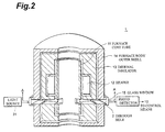
- Figs. 2 and 3 show the configuration of the furnace body 1.
- Fig. 2 is a perspective view of a vertical section of the furnace body 1
- Fig. 3 is a sectional view thereof taken along line A-A.
- the furnace body 1 has a four-layer structure in which a furnace core tube 11, a heater 12, a thermal insulator 13 and a furnace body outer shell 14, each shaped like a layer extending circumferentially, are concentrically disposed around the passage for passing the glass preform 4 therethrough.
- the heater 12 is disposed substantially at the middle portion of the furnace core tube 11 in its longitudinal direction.
- These members are configured substantially the same as those in the conventional furnace body shown in Figs. 7 and 8.
- the through hole 2 which is orthogonal to the passage for the glass preform 4 penetrates through the whole furnace body 1 at near the lower end of the heater 12.
- the through hole 2 is located at the similar level which the taper portion 6 is located.
- Glass windows 15 are attached to the furnace body outer shell 14 so as to seal both outer ends of the through hole 2. Through this hole 2 and glass windows 15, the taper portion 6 is visible from the outside the furnace body 1.
- the furnace core tube 11 and the furnace body 1 it is necessary for the furnace core tube 11 and the furnace body 1 to fully cover and non-contact the taper portion of the glass preform 4 so that the elongated body may not bend or distort its form.
- the region of a glass preform (corresponding to the taper portion) softened to such an extent that the glass preform can be elongated is within the range extending from the downstream end of the heater to about 300 mm downstream thereof.
- the furnace core tube 11 it is necessary for the furnace core tube 11 to cover this region as a whole, while it is required for the furnace body 1 to cover the range extending from the downstream end of the heater to about 600 mm downstream thereof.
- the outer diameter measuring device 3 configured as mentioned above is used for measuring the outer diameter of the glass preform 4, while it is necessary for the through hole 2 of the furnace body 1 to have a size in its circumferential direction not smaller than the outer diameter of the glass preform 4, it is sufficient for the through hole 2 to have a size in its axial direction corresponding the beam width of the laser beam. Even in view of accuracy and easiness in processing, a length of several mm in the axial direction is enough. The inventor has confirmed that, when the axial length of the through hole 2 is not greater than 30 mm, the heat distribution does not become uneven within the furnace body 1, whereby the elongated body is prevented from being distorted or bent.
- the through hole 2 is disposed near the optimal measuring position for the taper portion.
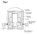
- This optimal measuring position as experimentally determined by the inventor, is generally located at a position downstream of the downstream end of the heater by 50 to 170 mm, though variable depending on the outer diameter of the glass preform before elongating, the outer diameter of the elongated body, the heater temperature, the inner diameter of the furnace core tube, and the like. Further, it has been found that, under a typical operating condition, it exists within the range approximately 70 to 120 mm downstream from the downstream end of the heater. In cases where various kinds of glass preforms are needed to be processed or the operating condition has to be changed, it is difficult for the through hole 2 to include the optimal measuring position under all the conditions. Accordingly, as shown in Fig.
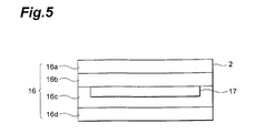
- the through hole 2 encompassing the range where the optimal measuring position can be included may be provided, and a heat insulating replacement member 16 may be inserted at a part corresponding to the furnace outer shell 14 and thermal insulator 13.
- the heat insulating replacement member 16 is formed with a slit 17 for transmitting therethrough the laser beam of the outer diameter measuring device 3.
- the width of the slit 17 in the axial direction of the furnace body 1 is set to several mm, the heat distribution within the furnace core tube 11 can be held so as not to generate unevenness.
- several kinds of heat insulating replacement members 16 respectively having slits 17 with different axial positions are prepared so as to be replaced in conformity to the optimal measuring position, the position for measuring the outer diameter of the taper portion can be adjusted easily.
- the axial position of the slit 17 can be adjusted easily, whereby the position for measuring the outer diameter of the taper portion can be adjusted more easily.
- the elongating apparatus While the glass preform 4 is heated as being passed through the furnace body 1, the lower chuck 8 is moved downward faster than the upper chuck 7, so as to elongate the glass preform 4, thereby yielding an elongated body 5.
- the taper portion 6 of the glass preform 4 is irradiated with the laser beam from the light source 3a through the through hole 2.
- the laser beam is irradiated as to scan the taper portion 6 transversally.
- the photodetector 3b is disposed outside the opposite end of the through hole 2 facing the light source 3a. The photodetector 3b detects the laser beam that is not blocked by the taper portion 6.
- the output of the photodetector 3b decreases; otherwise, the laser beam is directly made incident on the photodetector 3b, thereby increasing the output of the latter.
- the outer diameter of the taper portion 6 can be computed from the period of time in which the output is lowered.
- the control means 10 computes the outer diameter from the output of the photodetector 3b and controls the moving speeds of the chuck moving means 9a and 9b so as to keep the outer diameter at a desired value.
- the outer diameter of the resulting elongated body 5 is kept substantially constant, whereby a uniform elongated body can be made, due to the fact that, in the present invention, the outer diameter in the vicinity of the heater, i.e., that of the middle part of the taper portion, can be measured accurately, while the furnace core tube protects the whole taper portion including the measuring position from cooling down.
- the inventor elongated glass preforms by each of the elongating apparatus in accordance with the present invention and a conventional elongating apparatus, and compared the resulting elongated bodies with each other in terms of quality. In the following, the results of comparison will be explained.
- each furnace core tube was set to 200 mm. While the part of the elongating apparatus in accordance with the present invention extending from the downstream end of the heater to 600 mm downstream thereof was covered with the furnace body, the furnace body in the conventional elongating apparatus only covered the part extending from the downstream end of the heater to 60 mm downstream thereof.
- the elongating apparatus in accordance with the present invention was formed with a through hole having a width of 150 mm in its circumferential direction located at a part whose distance from the downstream end of the heater ranges from 60 to 130 mm. Inserted therein was a heat insulating replacement member having a slit with a width of 30 mm at a predetermined position in its axial direction.
- Glass preforms each having an outer diameter of 150 mm were used for making elongated bodies each having a final outer diameter of 70 mm.
- Each diameter measuring position for feedback control was set 110 mm downstream the downstream end of the heater. In each case, the heater temperature was controlled within the range of 1,900°C to 2,000°C.
- the elongated body obtained by use of the elongating apparatus in accordance with the present invention yielded a final diameter of 70 ⁇ 1 mm with its cross section keeping substantially a perfect circle state.
- the cross section of the elongated body became elliptical with a major axis of 71 ⁇ 1 mm and a minor axis of 70 ⁇ 1 mm.
- Glass preforms each having an outer diameter of 70 mm were used for making elongated bodies each with a final outer diameter of 30 mm.
- Each diameter measuring position for feedback control was set 80 mm downstream the downstream end of the heater. In each case, the heater temperature was controlled within the range of 1,800° to 1,900°C.
- the elongated body obtained by use of the elongating apparatus in accordance with the present invention yielded a final diameter of 30 ⁇ 0.5 mm with its cross section keeping substantially a perfect circle state.
- the cross section of the elongated body became elliptical with a major axis of 30 ⁇ 1 mm and a minor axis of 29 ⁇ 1 mm.
- the furnace body in accordance with the present invention can be made with approximately the same cost and labor as those of the conventional furnace body.
- the outer diameter of the taper portion can be measured from the outside of the furnace body. Accordingly, in the elongating apparatus and method in accordance with the present invention employing this furnace body, by the feedback control using thus measured diameter, an elongated body with less outer diameter fluctuation without bending or distortion can be obtained.
- each of both ends of the through hole is preferably sealed with a light-transmittable window material.
- the air is prevented from unnecessarily intruding therein, whereby the heat distribution within the furnace core tube can be kept from becoming uneven, and deterioration of the furnace body by unexpected oxidation of oxidizable material such as involving carbons can be prevented.
- the optimal position for measuring the outer diameter of the glass preform to be elongated can be changed easily, thus making it possible to effect more secure feedback control.
Landscapes
- Chemical & Material Sciences (AREA)
- Engineering & Computer Science (AREA)
- Materials Engineering (AREA)
- Organic Chemistry (AREA)
- Life Sciences & Earth Sciences (AREA)
- General Life Sciences & Earth Sciences (AREA)
- Geochemistry & Mineralogy (AREA)
- Manufacturing & Machinery (AREA)
- Re-Forming, After-Treatment, Cutting And Transporting Of Glass Products (AREA)
- Manufacture, Treatment Of Glass Fibers (AREA)
Claims (5)
- Ofengestell (1) für eine Dehnungseinrichtung für Glasvorformlinge, die dadurch einen länglichen Körper herstellt, dass der Glasvorformling (4) durch das Ofengestell (1) geleitet wird, und unter Erhitzung des Glasvorformlings der Glasvorformling (4) gedehnt wird, wobei das Ofengestell (1) aufweist:dadurch gekennzeichnet, dass die Entfernung von dem stromabwärtigen Ende des Heizteils (12) bis zu dem Durchgangsloch (2) 50 bis 170 mm beträgt.ein Ofenkernrohr (11), das zylinderförmig ausgebildet ist, durch welches der Glasvorformling (4) hindurchgeht, und welches in Axialrichtung eine ausreichende Länge aufweist, so dass der gedehnte Körper nicht verbogen oder verzerrt wird;ein Heizteil (12), dass an einem Außenumfangsabschnitt des Ofenkernrohres (11) angeordnet ist;eine Wärmeisolierung (13), welche das Ofenkernrohr (11) und das Heizteil (12) von außen in deren Umfangsrichtung und Axialrichtung umgibt; undeinen Ofengestellaußenmantel (14), in welchem die Wärmeisolierung (13) gehaltert ist;wobei ein Durchgangsloch (2) durch das Ofenkernrohr (11), die Wärmeisolierung (13) und den Ofengestellaußenmantel (14) in Richtung orthogonal zum Ofenkernrohr (11) hindurchgeht, und das Durchgangsloch (2) stromabwärts des Heizteils (12) angeordnet ist;
- Ofengestell nach Anspruch 1, welches weiterhin ein lichtdurchlässiges Fenster (13) aufweist, das von außen an jedem der beiden Enden des Durchgangslochs (2) angebracht ist, so dass es das Durchgangsloch abdichtet.
- Ofengestell nach Anspruch 1, bei welchem weiterhin ein Wärmeisolierteil (16) vorgesehen ist, das in das Durchgangsloch eingeführt ist, und einen Schlitz parallel zum Querschnitt in Querrichtung des Ofenkernrohres aufweist, wobei der Schlitz (17) orthogonal zur Zentrumsachse des Ofenkernrohrs (11) angeordnet ist.
- Dehnungseinrichtung für einen Glasvorformling (4), welche aufweist:ein Ofengestell (1) nach Anspruch 1;eine Zufuhrvorrichtung (7, 9a) zum Zuführen des Glasvorformlings (4) in das Ofengestell (1);eine Dehnungsvorrichtung (7, 9a, 8, 9b) zum Dehnen des Glasvorformlings (4) von dem Ofengestell (1);eine Lichtquelle (3a), die außerhalb des Ofengestellaußenmantels (14) an einem Ende des Durchgangsloches (2) des Ofengestells (1) angeordnet ist, um einen Lichtstrahl auf den Glasvorformling (4) im Innern des Ofenkernrohres (11) aufzustrahlen, durch das Durchgangsloch (2), und zur Abtastung des Glasvorformlings (4) in Querrichtung durch den Lichtstrahl;einen Photodetektor (3b), der außerhalb des anderen Endes des Ofengestellaußenmantels (14) an dem Durchgangsloch (2) angeordnet ist, um den durch das Durchgangsloch (2) ausgesandten Lichtstrahl zu detektieren; undeine Steuervorrichtung (10) zur Berechnung eines Außendurchmessers des Glasvorformlings (4) entsprechend einem Ausgangssignal des Photodetektors (3b), und zum Steuern der jeweiligen Zufuhr- und Dehnungsgeschwindigkeit der Zufuhr- und Dehnungsvorrichtungen (7, 9a, 8, 9b), damit der Außendurchmesser konstant gehalten wird.
- Verfahren zum Dehnen eines Glasvorformlings unter Verwendung eines Ofengestells (1) nach Anspruch 1, mit folgenden Schritten:Zuführen des Glasvorformlings (4) in das Heizofengestell (1), welches den Glasvorformling (4), ausgehend von einem Ende des Glasvorformlings (4), erwärmt und erweicht;Dehnen des Glasvorformlings (4) durch Einstellung einer Dehnungsgeschwindigkeit des Glasvorformlings von dem Heizofengestell (1) höher als eine Zufuhrgeschwindigkeit des Glasvorformlings (4) in das Heizofengestell (1);Abtastung eines sich verjüngenden Abschnitts des Glasvorformlings (4) in Querrichtung, der gedehnt wird, durch den Lichtstrahl, wobei die Abtastposition 50 - 170 mm stromabwärts in Bezug auf eine stromabwärtige Endposition des Heizteils (12) des Heizofengestells (1) angeordnet ist;Messung eines Außendurchmessers des sich verjüngenden Abschnitts an der Abtastposition durch Detektieren des Lichts, das von dem Durchgangsloch (2) an der Abtastposition ausgesandt wird; undSteuern der Zufuhr- und Dehnungsgeschwindigkeit des Glasvorformlings (4) in Bezug auf das Ofengestell (1) auf solche Weise, dass der Außendurchmesser des sich verjüngenden Abschnitts an der Abtastposition konstant gehalten wird.
Applications Claiming Priority (3)
| Application Number | Priority Date | Filing Date | Title |
|---|---|---|---|
| JP9346897 | 1997-04-11 | ||
| JP93468/97 | 1997-04-11 | ||
| JP09346897A JP3159116B2 (ja) | 1997-04-11 | 1997-04-11 | ガラス母材の延伸機および延伸方法 |
Publications (2)
| Publication Number | Publication Date |
|---|---|
| EP0870736A1 EP0870736A1 (de) | 1998-10-14 |
| EP0870736B1 true EP0870736B1 (de) | 2001-08-01 |
Family
ID=14083179
Family Applications (1)
| Application Number | Title | Priority Date | Filing Date |
|---|---|---|---|
| EP98106453A Expired - Lifetime EP0870736B1 (de) | 1997-04-11 | 1998-04-08 | Ofen und Verfahren zum Ziehen eines Stabs aus einer Glasvorform |
Country Status (4)
| Country | Link |
|---|---|
| US (1) | US5942019A (de) |
| EP (1) | EP0870736B1 (de) |
| JP (1) | JP3159116B2 (de) |
| DE (1) | DE69801253T2 (de) |
Families Citing this family (18)
| Publication number | Priority date | Publication date | Assignee | Title |
|---|---|---|---|---|
| JP3777746B2 (ja) * | 1997-09-26 | 2006-05-24 | 住友電気工業株式会社 | ガラス母材の延伸方法 |
| DE69931825T8 (de) | 1998-11-05 | 2007-09-20 | Shin-Etsu Chemical Co., Ltd. | Verfahren und Vorrichtung zum Herstellen einer Vorform und einer optischen Faser aus der Vorform |
| JP3437480B2 (ja) * | 1999-03-12 | 2003-08-18 | 信越化学工業株式会社 | ガラス母材延伸装置の調整方法 |
| DE19915509C1 (de) * | 1999-04-07 | 2000-06-08 | Heraeus Quarzglas | Verfahren für die Herstellung eines zylinderförmigen Bauteils aus Quarzglas und dafür geeignete Vorrichtung |
| US6553790B1 (en) * | 2000-05-09 | 2003-04-29 | Fitel Usa Corp. | Process for fabricating optical fiber involving tuning of core diameter profile |
| JP4360585B2 (ja) * | 2001-01-10 | 2009-11-11 | 信越化学工業株式会社 | ガラス母材延伸装置 |
| JP3812357B2 (ja) * | 2001-03-30 | 2006-08-23 | 住友電気工業株式会社 | 光ファイバ母材の延伸方法及び延伸装置 |
| KR100383627B1 (ko) * | 2001-06-23 | 2003-05-14 | 삼성전자주식회사 | 변형화학 기상증착법을 이용한 광섬유 모재 제조장치에서자동 석영관 레벨링장치 |
| JP2003048732A (ja) * | 2001-07-31 | 2003-02-21 | Nippon Electric Glass Co Ltd | 精密ガラス管の成形方法 |
| GB0119664D0 (en) * | 2001-08-11 | 2001-10-03 | Stanelco Fibre Optics Ltd | Glass stretching furnace |
| FR2839063B1 (fr) * | 2002-04-29 | 2005-01-07 | Cit Alcatel | Procede de fabrication de preformes de fibres optiques |
| EP1559691A4 (de) * | 2002-06-19 | 2006-03-01 | Sumitomo Electric Industries | Verfahren zum ziehen von glasgrundmaterial und ziehmaschine zur verwendung dabei |
| EP1525167A1 (de) * | 2002-07-30 | 2005-04-27 | Pirelli & C. S.p.A. | Verfahren und vorrichtung zum ausziehen einer vorform für optische fasern |
| FI20021564A0 (fi) * | 2002-09-02 | 2002-09-02 | Nextrom Holding Sa | Sovitelma preformin valmistamiseksi |
| JP2005104756A (ja) * | 2003-09-29 | 2005-04-21 | Sumitomo Electric Ind Ltd | 光ファイバ製造方法及び装置 |
| DE102009014418B3 (de) * | 2009-03-26 | 2010-04-15 | Heraeus Quarzglas Gmbh & Co. Kg | Ziehverfahren zur Herstellung zylinderförmiger Bauteile aus Quarzglas |
| EP3158284B1 (de) | 2014-06-17 | 2022-03-16 | Heraeus Quartz North America LLC | Vorrichtung und verfahren zur erwärmung und vermessung von transparenten zylinderförmigen artikeln |
| EP3088370B1 (de) * | 2015-04-28 | 2018-09-26 | Heraeus Quarzglas GmbH & Co. KG | Verfahren und vorrichtung zur herstellung eines rohres aus glas |
Family Cites Families (17)
| Publication number | Priority date | Publication date | Assignee | Title |
|---|---|---|---|---|
| US3865564A (en) * | 1973-07-09 | 1975-02-11 | Bell Telephone Labor Inc | Fabrication of glass fibers from preform by lasers |
| FR2383138A1 (fr) * | 1977-03-09 | 1978-10-06 | Gouronnec Alain | Equipement d'etirage de fibre optique a partir d'une preforme, perfectionne en ce qui concerne la regulation de la vitesse du tambour d'etirage et le demarrage automatique du fibrage |
| FR2383137A1 (fr) * | 1977-03-09 | 1978-10-06 | Gouronnec Alain | Equipement d'etirage de fibre optique a partir d'une preforme, perfectionne en ce qui concerne la regulation de la temperature du four et celle de la vitesse de descente de la preforme |
| JPS5918325B2 (ja) * | 1979-09-20 | 1984-04-26 | 日本電信電話株式会社 | 光ファイバ母材の製造方法 |
| JPS5792534A (en) * | 1980-11-28 | 1982-06-09 | Nippon Telegr & Teleph Corp <Ntt> | Elongation of glass rod |
| US4331463A (en) * | 1981-06-22 | 1982-05-25 | Gte Laboratories Incorporated | Self-centering apparatus for making optical fibers |
| JPS63195139A (ja) * | 1987-02-09 | 1988-08-12 | Hitachi Cable Ltd | ガラスロツド延伸装置 |
| JPH0483726A (ja) * | 1990-07-23 | 1992-03-17 | Hitachi Cable Ltd | ガラス母材の延伸方法 |
| JPH0570165A (ja) * | 1991-09-18 | 1993-03-23 | Fujikura Ltd | 光フアイバ母材の延伸装置 |
| US5228893A (en) * | 1991-11-27 | 1993-07-20 | At&T Bell Laboratories | Optical fiber tension monitoring technique |
| JPH05294662A (ja) * | 1992-04-14 | 1993-11-09 | Furukawa Electric Co Ltd:The | フッ化物ガラス光ファイバ母材の延伸方法 |
| JPH06239639A (ja) * | 1993-02-17 | 1994-08-30 | Furukawa Electric Co Ltd:The | 光ファイバガラス母材の延伸方法 |
| KR950000588A (ko) * | 1993-06-18 | 1995-01-03 | 쿠라우찌 노리타카 | 싱글모드광파이버모재의 제조방법 |
| DE4339077C2 (de) * | 1993-11-16 | 1997-03-06 | Rheydt Kabelwerk Ag | Verfahren zum Ziehen einer optischen Faser und Vorrichtung zu dessen Durchführung |
| JP3824671B2 (ja) * | 1994-07-21 | 2006-09-20 | 古河電気工業株式会社 | ガラスロッドの延伸方法 |
| JPH08310827A (ja) * | 1995-05-12 | 1996-11-26 | Fujikura Ltd | 光ファイバ母材の延伸用加熱炉 |
| SE511083C2 (sv) * | 1995-12-06 | 1999-08-02 | Sumitomo Electric Industries | Förfarande för att förlänga glasförform |
-
1997
- 1997-04-11 JP JP09346897A patent/JP3159116B2/ja not_active Expired - Fee Related
-
1998
- 1998-04-08 DE DE69801253T patent/DE69801253T2/de not_active Expired - Fee Related
- 1998-04-08 EP EP98106453A patent/EP0870736B1/de not_active Expired - Lifetime
- 1998-04-09 US US09/057,336 patent/US5942019A/en not_active Expired - Lifetime
Also Published As
| Publication number | Publication date |
|---|---|
| JPH10287441A (ja) | 1998-10-27 |
| JP3159116B2 (ja) | 2001-04-23 |
| DE69801253T2 (de) | 2002-03-14 |
| US5942019A (en) | 1999-08-24 |
| DE69801253D1 (de) | 2001-09-06 |
| EP0870736A1 (de) | 1998-10-14 |
Similar Documents
| Publication | Publication Date | Title |
|---|---|---|
| EP0870736B1 (de) | Ofen und Verfahren zum Ziehen eines Stabs aus einer Glasvorform | |
| KR100227925B1 (ko) | 원통형 석영 유리 실린더 제조방법 및 장치 | |
| GB2105705A (en) | Methods of and apparatus for heating a fiber preform | |
| HK1000532B (en) | Method and apparatus for drawing optical fibers | |
| RU2116269C1 (ru) | Печь для формования оптических волокон и способ соединения заготовок оптических волокон | |
| RU96119751A (ru) | Устройство и способ формирования оптических волокон | |
| EP0885852B1 (de) | Verfahren und Vorrichtung zum Ziehen einer Glasvorform | |
| JP2007513855A (ja) | 円筒状ガラス体をつくる垂直延伸法とその方法を実施する装置 | |
| AU640736B2 (en) | Manufacturing of optical waveguide with a metallic sheath | |
| FI105678B (fi) | Laite ja menetelmä pitkänomaisen lasiaunion liekkikiillottamiseksi | |
| JP3812357B2 (ja) | 光ファイバ母材の延伸方法及び延伸装置 | |
| US20090129731A1 (en) | Method for Operating a Device for Splicing Optical Waveguides | |
| US5843199A (en) | Method and device for fire-polishing a lengthwise extended glass body | |
| FI73847B (fi) | Anordning foer torrnaetning av en kabel. | |
| EP1988061A1 (de) | Verfahren zur Verlängerung eines Glaskörpers | |
| JPH1111970A (ja) | ガラスロッドの延伸装置及び延伸方法 | |
| EP0234325A2 (de) | Multimode faseroptischer Koppler und Verfahren zu dessen Herstellung | |
| JP4076158B2 (ja) | 光ファイバ母材の延伸方法 | |
| JP4258610B2 (ja) | ガラス母材の延伸方法 | |
| BR0104334A (pt) | Processo e aparelho para controlar um diâmetro externo de um tubo de isca de preforma durante um processo de deposição de camada de vidro | |
| EP1559691A1 (de) | Verfahren zum ziehen von glasgrundmaterial und ziehmaschine zur verwendung dabei | |
| JP2001006872A (ja) | マイクロ波吸収性プラスチックからなる部材を加熱する装置。 | |
| JP2749669B2 (ja) | ガラス棒の延伸方法 | |
| JP3112893B2 (ja) | ガラス母材の延伸方法 | |
| KR100411480B1 (ko) | 폴리머 광섬유 인발을 위한 가열장치 |
Legal Events
| Date | Code | Title | Description |
|---|---|---|---|
| PUAI | Public reference made under article 153(3) epc to a published international application that has entered the european phase |
Free format text: ORIGINAL CODE: 0009012 |
|
| AK | Designated contracting states |
Kind code of ref document: A1 Designated state(s): DE GB |
|
| AX | Request for extension of the european patent |
Free format text: AL;LT;LV;MK;RO;SI |
|
| 17P | Request for examination filed |
Effective date: 19990210 |
|
| 17Q | First examination report despatched |
Effective date: 19990420 |
|
| AKX | Designation fees paid |
Free format text: DE GB |
|
| GRAG | Despatch of communication of intention to grant |
Free format text: ORIGINAL CODE: EPIDOS AGRA |
|
| RTI1 | Title (correction) |
Free format text: FURNACE AND METHOD FOR ELONGATING A GLASS PREFORM TO A DRAWN ROD |
|
| GRAG | Despatch of communication of intention to grant |
Free format text: ORIGINAL CODE: EPIDOS AGRA |
|
| GRAH | Despatch of communication of intention to grant a patent |
Free format text: ORIGINAL CODE: EPIDOS IGRA |
|
| GRAH | Despatch of communication of intention to grant a patent |
Free format text: ORIGINAL CODE: EPIDOS IGRA |
|
| GRAA | (expected) grant |
Free format text: ORIGINAL CODE: 0009210 |
|
| AK | Designated contracting states |
Kind code of ref document: B1 Designated state(s): DE GB |
|
| REF | Corresponds to: |
Ref document number: 69801253 Country of ref document: DE Date of ref document: 20010906 |
|
| REG | Reference to a national code |
Ref country code: GB Ref legal event code: IF02 |
|
| PLBE | No opposition filed within time limit |
Free format text: ORIGINAL CODE: 0009261 |
|
| STAA | Information on the status of an ep patent application or granted ep patent |
Free format text: STATUS: NO OPPOSITION FILED WITHIN TIME LIMIT |
|
| 26N | No opposition filed | ||
| PGFP | Annual fee paid to national office [announced via postgrant information from national office to epo] |
Ref country code: DE Payment date: 20050331 Year of fee payment: 8 |
|
| PGFP | Annual fee paid to national office [announced via postgrant information from national office to epo] |
Ref country code: GB Payment date: 20050406 Year of fee payment: 8 |
|
| PG25 | Lapsed in a contracting state [announced via postgrant information from national office to epo] |
Ref country code: GB Free format text: LAPSE BECAUSE OF NON-PAYMENT OF DUE FEES Effective date: 20060408 |
|
| PG25 | Lapsed in a contracting state [announced via postgrant information from national office to epo] |
Ref country code: DE Free format text: LAPSE BECAUSE OF NON-PAYMENT OF DUE FEES Effective date: 20061101 |
|
| GBPC | Gb: european patent ceased through non-payment of renewal fee |
Effective date: 20060408 |