EP0870883A2 - Vorgefertigte Balken für Decken und/oder aus einem Gitter und Ziegeln hergestellter Verblendsturz, und Ziegel dafür - Google Patents
Vorgefertigte Balken für Decken und/oder aus einem Gitter und Ziegeln hergestellter Verblendsturz, und Ziegel dafür Download PDFInfo
- Publication number
- EP0870883A2 EP0870883A2 EP98106305A EP98106305A EP0870883A2 EP 0870883 A2 EP0870883 A2 EP 0870883A2 EP 98106305 A EP98106305 A EP 98106305A EP 98106305 A EP98106305 A EP 98106305A EP 0870883 A2 EP0870883 A2 EP 0870883A2
- Authority
- EP
- European Patent Office
- Prior art keywords
- brick
- brick base
- joist
- base
- bolt
- Prior art date
- Legal status (The legal status is an assumption and is not a legal conclusion. Google has not performed a legal analysis and makes no representation as to the accuracy of the status listed.)
- Withdrawn
Links
Images
Classifications
-
- E—FIXED CONSTRUCTIONS
- E04—BUILDING
- E04C—STRUCTURAL ELEMENTS; BUILDING MATERIALS
- E04C5/00—Reinforcing elements, e.g. for concrete; Auxiliary elements therefor
- E04C5/01—Reinforcing elements of metal, e.g. with non-structural coatings
- E04C5/06—Reinforcing elements of metal, e.g. with non-structural coatings of high bending resistance, i.e. of essentially three-dimensional [3D] extent, e.g. lattice girders
- E04C5/065—Light-weight girders, e.g. with precast parts
- E04C5/0653—Light-weight girders, e.g. with precast parts with precast parts
- E04C5/0656—Light-weight girders, e.g. with precast parts with precast parts with lost formwork
-
- E—FIXED CONSTRUCTIONS
- E04—BUILDING
- E04C—STRUCTURAL ELEMENTS; BUILDING MATERIALS
- E04C3/00—Structural elongated elements designed for load-supporting
- E04C3/02—Joists; Girders, trusses, or trusslike structures, e.g. prefabricated; Lintels; Transoms; Braces
-
- E—FIXED CONSTRUCTIONS
- E04—BUILDING
- E04C—STRUCTURAL ELEMENTS; BUILDING MATERIALS
- E04C3/00—Structural elongated elements designed for load-supporting
- E04C3/02—Joists; Girders, trusses, or trusslike structures, e.g. prefabricated; Lintels; Transoms; Braces
- E04C2003/023—Lintels
Definitions
- the invention concerns a prefabricated floor joist made of a framework and brick, constructed so that one or more additional iron bars, in addition to the framework, can be positioned at a given distance from the bottom of the brick base that makes up the joist, said distance being sufficient for the iron bar itself to be covered all around by a concrete layer.
- the regulations in force regarding the construction of floors require, among the other things, that the metal reinforcement belonging to the floor be structured so that any metal surface must be surrounded in any direction by a layer of cement mortar whose minimum thickness must be 5 mm. This is required in order to ensure maximum cohesion between cement and iron structure and also to prevent the iron from deteriorating over time due to the direct contact with the brick or the atmosphere.
- one of the methods presently adopted includes the vibration of the cement before its hardening, so that owing to the vibrations the cement mortar can penetrate among the additional iron bars and the bottom of the brick base, thus ensuring a minimum distance between said additional iron bars and said brick base.
- the raising of the additional iron bars with respect to the bottom of the brick base is obtained by means of projections carried out during the molding of the brick bases that make up the joist. These projections are situated on the bottom at regular intervals and are obtained through a sort of impression made on the bottom of the brick base by raising the brick with respect to the bottom itself.
- the present invention is aimed at eliminating the above mentioned drawbacks.
- the goal of the invention is the implementation of a prefabricated joist in which the additional iron bars provided to reinforce the structure of the metal framework are spaced from the bottom of the brick bases.
- the additional iron bars provided to reinforce the structure of the metal framework are spaced from the bottom of the brick bases.
- a prefabricated brick joist for floors or lintels that, according to the main claim, comprises a plurality of substantially U-shaped brick bases defining a channel in which the iron bars belonging to the framework or additional iron bars are positioned and which is to be filled with concrete, said joist being characterized in that it comprises a plurality of U-bolts having their ends buried in the brick base and being spaced at regular intervals and aligned with one another in such a way as to define at least one rectilinear support for at least one additional iron bar spaced from the bottom of said brick base, said iron bar remaining within the outline defined by the brick base channel filled with concrete.
- each U-bolt is made of a wire positioned in the brick before this is baked.
- Metal straps or other similar materials can be used instead of wire, provided that they are compatible with concrete.
- Each brick base is preferably, but not necessarily, provided with an U-bolt aligned with other U-bolts belonging to other brick bases.
- the joist can even make use of only some of the brick bases with U-bolt belonging to the invention, but not necessarily of all of them.
- the important feature is that the support offered by the U-bolts must be such as to guarantee that every single point of the additional iron bar is spaced from the brick base bottom.
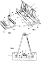
- the joist indicated as a whole by 1, is provided with a plurality of substantially U-shaped brick bases 2 suitable for defining a channel 3 inside which the base of a framework indicated by 4 is to be placed, whose base iron bars 41 and 42 rest on the concave sides 21 and 22 present in the brick bases 2.
- a U-bolt 5 with two sides 51 and 52 and a concave part 53 is introduced at a predetermined distance from one of the two ends of the brick base.
- the ends 51 and 52 are buried in the bottom 23 of the brick base 2 for a length sufficient to fix said U-bolt 5 when the brick is still malleable, because it has not been baked yet.
- the U-bolt 5 will be definitively fixed in the brick base 2.
- the burying of the U-bolt 5 is carried out in such a way as to guarantee that, as shown in Figure 3, the distance of the base 53 of the U-bolt from the bottom 23 is at least 5 mm, as prescribed by the regulations in force.
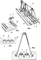
- the brick base 20, shown also in Figure 5 is provided with two equally spaced U-bolts 5, as shown in Figure 4, which constitute two distinct rectilinear supports for the two additional iron bars 7 and 8.
- the U-bolts are preferably constructed with the surface 53 slightly concave, in such a way as to guarantee that the additional iron bars will be held in the correct position during the concrete casting.
- the U-bolts 5 are made of a metal strap and are placed in the brick before its baking by means of a machine resembling a seamer.
- the U-bolts can also be made of wire or other material, provided that any material used is compatible with concrete and with the prefabricated item.
- Figure 7 shows a section of a type of brick base 30 used for the construction of door and window lintels.
- the brick base is filled with concrete after the introduction of the iron bars 9 that must also be spaced from the bottom 31 of the brick base. Therefore, even in this case the required distance between the iron bars and the brick base bottom is guaranteed.
Landscapes
- Engineering & Computer Science (AREA)
- Architecture (AREA)
- Civil Engineering (AREA)
- Structural Engineering (AREA)
- Floor Finish (AREA)
- Rod-Shaped Construction Members (AREA)
Applications Claiming Priority (2)
| Application Number | Priority Date | Filing Date | Title |
|---|---|---|---|
| ITVI970056 | 1997-04-11 | ||
| IT97VI000056A IT1292977B1 (it) | 1997-04-11 | 1997-04-11 | Travetto per solai e/o architravi prefabbricati con traliccio e laterizio e fondello per tale travetto. |
Publications (2)
| Publication Number | Publication Date |
|---|---|
| EP0870883A2 true EP0870883A2 (de) | 1998-10-14 |
| EP0870883A3 EP0870883A3 (de) | 1999-11-24 |
Family
ID=11426328
Family Applications (1)
| Application Number | Title | Priority Date | Filing Date |
|---|---|---|---|
| EP98106305A Withdrawn EP0870883A3 (de) | 1997-04-11 | 1998-04-07 | Vorgefertigte Balken für Decken und/oder aus einem Gitter und Ziegeln hergestellter Verblendsturz, und Ziegel dafür |
Country Status (3)
| Country | Link |
|---|---|
| EP (1) | EP0870883A3 (de) |
| HR (1) | HRP980200A2 (de) |
| IT (1) | IT1292977B1 (de) |
Cited By (6)
| Publication number | Priority date | Publication date | Assignee | Title |
|---|---|---|---|---|
| EP1445391A3 (de) * | 2003-02-03 | 2005-09-21 | Coperlegno S.R.L. | Vorgefertigte Bauelemente zur Herstellung von Bodenplatten, Böden oder Wände mit freigelegten Holzbalken |
| WO2009010366A1 (en) * | 2007-07-19 | 2009-01-22 | Leone, Lucio | Improved girders for reinforcing concrete and method for connecting them to pillars in order to provide continuity from bay to bay |
| US7784235B2 (en) | 2004-05-11 | 2010-08-31 | Plastedil S.A. | Load bearing construction element, in particular for manufacturing building floors, and floor structure incorporating such element |
| FR2956139A1 (fr) * | 2010-02-08 | 2011-08-12 | Gerard Sekrane | Element de coffrage pour la construction d'une poutrelle |
| ITVI20100246A1 (it) * | 2010-09-10 | 2012-03-11 | Ugo Zanrosso | Fondello in laterizio per la realizzazione di travetti prefabbricati con traliccio elettrosaldato ed armatura longitudinale |
| FR3023312A1 (fr) * | 2014-07-07 | 2016-01-08 | Isoltop | Poutrelle pour la realisation d'un plancher |
Family Cites Families (5)
| Publication number | Priority date | Publication date | Assignee | Title |
|---|---|---|---|---|
| DE2017101A1 (de) * | 1970-04-10 | 1971-10-21 | Oltmanns, Heinrich, 2901 Jeddeloh | Distanzhalter für Bewehmngsstäbe in Balkenschalen, insbesondere Betonbalkenschalen für Fensterstürze |
| DE2404281A1 (de) * | 1974-01-30 | 1975-08-07 | Hermann Dr Datz | Stahlleichtgittertraeger |
| IT8261999U1 (it) * | 1982-10-06 | 1984-04-06 | Spil Impianti Spa | Travetto laterocementizio armato |
| FR2548718A1 (fr) * | 1983-07-08 | 1985-01-11 | Brochet Denis | Dispositifs eliminant les deteriorations causees par l'etaiement aux sous-faces des planchers isolants nervures en beton arme |
| IT238642Y1 (it) * | 1995-06-08 | 2000-11-13 | Barbieri Ignazio | Fondello in laterizio per travetti prefabbricati con traliccio |
-
1997
- 1997-04-11 IT IT97VI000056A patent/IT1292977B1/it active IP Right Grant
-
1998
- 1998-04-07 EP EP98106305A patent/EP0870883A3/de not_active Withdrawn
- 1998-04-09 HR HRVI97A000056A patent/HRP980200A2/hr not_active Application Discontinuation
Cited By (10)
| Publication number | Priority date | Publication date | Assignee | Title |
|---|---|---|---|---|
| EP1445391A3 (de) * | 2003-02-03 | 2005-09-21 | Coperlegno S.R.L. | Vorgefertigte Bauelemente zur Herstellung von Bodenplatten, Böden oder Wände mit freigelegten Holzbalken |
| US7281357B2 (en) | 2003-02-03 | 2007-10-16 | Coperlegno S.R.L. | Prefabricated components for making floor slabs, floors and walls with exposed wood beams for small buildings |
| US7784235B2 (en) | 2004-05-11 | 2010-08-31 | Plastedil S.A. | Load bearing construction element, in particular for manufacturing building floors, and floor structure incorporating such element |
| EP1756375B1 (de) * | 2004-05-11 | 2012-01-04 | Plastedil S.A. | Tragendes konstruktionselement, besonders für die herstellung von gebäudedecken und deckenstruktur mit einem solchen element |
| WO2009010366A1 (en) * | 2007-07-19 | 2009-01-22 | Leone, Lucio | Improved girders for reinforcing concrete and method for connecting them to pillars in order to provide continuity from bay to bay |
| FR2956139A1 (fr) * | 2010-02-08 | 2011-08-12 | Gerard Sekrane | Element de coffrage pour la construction d'une poutrelle |
| EP2444567A1 (de) * | 2010-02-08 | 2012-04-25 | Gérard Sekrane | Verschalungselement zum Bau eines Trägers |
| ITVI20100246A1 (it) * | 2010-09-10 | 2012-03-11 | Ugo Zanrosso | Fondello in laterizio per la realizzazione di travetti prefabbricati con traliccio elettrosaldato ed armatura longitudinale |
| FR3023312A1 (fr) * | 2014-07-07 | 2016-01-08 | Isoltop | Poutrelle pour la realisation d'un plancher |
| WO2016005679A1 (fr) | 2014-07-07 | 2016-01-14 | Isoltop (Sas) | Poutrelle pour la realisation d'un plancher |
Also Published As
| Publication number | Publication date |
|---|---|
| ITVI970056A1 (it) | 1997-07-11 |
| HRP980200A2 (en) | 1999-02-28 |
| IT1292977B1 (it) | 1999-02-11 |
| EP0870883A3 (de) | 1999-11-24 |
| ITVI970056A0 (de) | 1997-04-11 |
Similar Documents
| Publication | Publication Date | Title |
|---|---|---|
| US5398470A (en) | Reinforcement body for a floor slab | |
| US4974381A (en) | Tie anchor and method for manufacturing insulated concrete sandwich panels | |
| US6003281A (en) | Reinforced concrete structural elements | |
| US4068420A (en) | Demountable multiple level building structures | |
| US5809732A (en) | M/bed block system | |
| WO2009010366A1 (en) | Improved girders for reinforcing concrete and method for connecting them to pillars in order to provide continuity from bay to bay | |
| US5408799A (en) | Members for reinforcing, supporting and tying steel bars for reinforcing concrete | |
| US4349492A (en) | Method of putting in a partition of insulation material inside concrete walls which are cast in a vertical position in an industrial building site | |
| GB2522887A (en) | Shuttering system | |
| US6367209B1 (en) | Box lintel | |
| GB2139664A (en) | Spacing device for reinforced concrete construction | |
| US3195209A (en) | Concrete erection and stripping system | |
| US7448171B1 (en) | Joist support structure adapted to be embedded into a foundation wall | |
| EP1455022B1 (de) | Verfahren zur Herstellung einer Pfahlgründung | |
| EP0870883A3 (de) | Vorgefertigte Balken für Decken und/oder aus einem Gitter und Ziegeln hergestellter Verblendsturz, und Ziegel dafür | |
| US4191002A (en) | Demountable multiple level building structure | |
| KR102178265B1 (ko) | 기설 콘크리트 벽체의 내진보강장치 및 내진보강공법 | |
| JP3778392B2 (ja) | 基礎ブロック | |
| JP2754523B2 (ja) | 斜面安定化工法 | |
| WO1991000400A1 (en) | Prefabricated floor slab | |
| JP2002309713A (ja) | Pc鋼材定着部の構造 | |
| RU2023839C1 (ru) | Способ усиления сборных железобетонных многопустотных панелей перекрытий | |
| US1794409A (en) | Concrete structure | |
| KR0127135Y1 (ko) | 콘크리트몰탈타설기준대를 가진 철근받침대 | |
| JP3688800B2 (ja) | 壁パネル下地金物の固定構造 |
Legal Events
| Date | Code | Title | Description |
|---|---|---|---|
| PUAI | Public reference made under article 153(3) epc to a published international application that has entered the european phase |
Free format text: ORIGINAL CODE: 0009012 |
|
| AK | Designated contracting states |
Kind code of ref document: A2 Designated state(s): AT BE CH CY DE DK ES FI FR GB GR IE IT LI LU MC NL PT SE |
|
| AX | Request for extension of the european patent |
Free format text: AL;LT;LV;MK;RO;SI |
|
| PUAL | Search report despatched |
Free format text: ORIGINAL CODE: 0009013 |
|
| AK | Designated contracting states |
Kind code of ref document: A3 Designated state(s): AT BE CH CY DE DK ES FI FR GB GR IE IT LI LU MC NL PT SE |
|
| AX | Request for extension of the european patent |
Free format text: AL;LT;LV;MK;RO;SI |
|
| RIC1 | Information provided on ipc code assigned before grant |
Free format text: 6E 04C 5/065 A, 6E 04C 3/02 B, 6E 04C 5/18 B |
|
| STAA | Information on the status of an ep patent application or granted ep patent |
Free format text: STATUS: THE APPLICATION HAS BEEN WITHDRAWN |
|
| 18W | Application withdrawn |
Withdrawal date: 20000530 |