EP2444567A1 - Verschalungselement zum Bau eines Trägers - Google Patents
Verschalungselement zum Bau eines Trägers Download PDFInfo
- Publication number
- EP2444567A1 EP2444567A1 EP11153695A EP11153695A EP2444567A1 EP 2444567 A1 EP2444567 A1 EP 2444567A1 EP 11153695 A EP11153695 A EP 11153695A EP 11153695 A EP11153695 A EP 11153695A EP 2444567 A1 EP2444567 A1 EP 2444567A1
- Authority
- EP
- European Patent Office
- Prior art keywords
- profile
- formwork
- shuttering
- elements
- sole
- Prior art date
- Legal status (The legal status is an assumption and is not a legal conclusion. Google has not performed a legal analysis and makes no representation as to the accuracy of the status listed.)
- Granted
Links
Images


Classifications
-
- E—FIXED CONSTRUCTIONS
- E04—BUILDING
- E04C—STRUCTURAL ELEMENTS; BUILDING MATERIALS
- E04C5/00—Reinforcing elements, e.g. for concrete; Auxiliary elements therefor
- E04C5/01—Reinforcing elements of metal, e.g. with non-structural coatings
- E04C5/06—Reinforcing elements of metal, e.g. with non-structural coatings of high bending resistance, i.e. of essentially three-dimensional [3D] extent, e.g. lattice girders
- E04C5/065—Light-weight girders, e.g. with precast parts
- E04C5/0653—Light-weight girders, e.g. with precast parts with precast parts
- E04C5/0656—Light-weight girders, e.g. with precast parts with precast parts with lost formwork
-
- E—FIXED CONSTRUCTIONS
- E04—BUILDING
- E04C—STRUCTURAL ELEMENTS; BUILDING MATERIALS
- E04C3/00—Structural elongated elements designed for load-supporting
- E04C3/02—Joists; Girders, trusses, or trusslike structures, e.g. prefabricated; Lintels; Transoms; Braces
- E04C3/20—Joists; Girders, trusses, or trusslike structures, e.g. prefabricated; Lintels; Transoms; Braces of concrete or other stone-like material, e.g. with reinforcements or tensioning members
Definitions
- the invention relates to a formwork element for the construction of beams used, in particular, for floors manufactured through beams / interjoists or even balconies or loggia type constructions.
- the heel is formed, in known manner, by a U-shaped sheet metal profile serving as a formwork in which the concrete is poured.
- This profile is fixed permanently during the pouring of the concrete of the beam, the latter becoming self-supporting.
- self-supporting beams are ISOLTOP® beams filled with polyurethane foam.
- associates also called hourdis, which are pieces intended to rest on the beams, to be used for the formwork of the floor during the pouring of the concrete of paving of the floor.
- floors including thermally insulating intervous obtained by cutting or molding a body of cellular insulating material, for example expanded polystyrene.
- Euromac 2®-type interjoists can be mentioned.
- a known structure thus provides for adding an insulating structure of Placoplatre type under the beams by means of fasteners adapted to ensure the fire resistance of the latter.
- Another known work provides insulating interjoists protruding cantilever so as to cover the lower surface of adjacent beams to thermally insulate it.
- the known floors do not have, sometimes, the thermal performance necessary for the fire resistance of buildings.
- An object of the present invention is to overcome the aforementioned drawbacks.
- Another object of the present invention is to provide beams providing effective thermal insulation while reducing the mass of the floor frame.
- Another object of the present invention is to provide beams providing easy and fast construction and assembly.
- Another object of the invention is to provide beams that can meet satisfactory thermal performance to be certified according to the new thermal standards of building construction.
- a shuttering element for the construction of a reinforcement beam comprising a profile intended to be fixed to the reinforcement and to receive means for partially embedding said remarkable reinforcement in that said profile is formed of composite material to ensure the fire resistance of said beam.
- the formwork element ensures the fire resistance of the beam and the entire floor has a continuous fire resistance, without thermal bridges.
- the invention also relates to a remarkable beam in that it comprises at least one shuttering element as mentioned above and a metal or composite reinforcement intended to be fixed to said shuttering element.
- the invention also relates to a building assembly comprising a beam as mentioned above and transverse reinforcement bars of composite material adapted for traversing the shuttering elements of said beam.
- At least two formwork elements are configured to be installed on a wall base or a construction element and to support a beam through one or more recesses each adapted to receive a transverse reinforcing bar .
- a skeleton of a floor consists of self-supporting beams parallel to each other, intended to be interconnected by filling elements such as slabs or interjoists.
- a concrete pour for floor paving ensures the interlocking joints and beams.
- a self-supporting beam comprises, in a conventional manner, a reinforcing metal reinforcement embedded in a heel formed of a suitable material whose contours are delimited by a formwork element remaining permanently after filling the beam with the material.
- the heel is intended in particular to support interjoists located on either side of the beam.
- beams include a prefabricated truss on the manufacturing table or manufactured on site or a prestressed beam.
- the beam 10 comprises a structural element acting as formwork, designated by the general reference 100.
- Such a shuttering element 100 comprises a profile 101, of U cross-section, having a flange 110 and two parallel lateral wings 150, disposed on either side of said flange 110.
- the metal reinforcement 200 forming the web of the beam 100 is intended to be fixed on the soleplate 110 in the concavity of the profile 101.
- This longitudinal reinforcement 200 conventionally comprises an upper bar 201 and two parallel lower bars 202, 203, each lower bar 202, 203 being secured to the upper bar 201 by a mesh 204.
- This lattice 204 comprises a series of inclined bars, which form a triangulated assembly secured by welding with the upper bars 201 and lower 202,203 of the frame 200.
- the bars of the lattice 204 may be arranged in a different manner depending on the triangulation system adopted.
- the armature 200 is not metallic but formed of reinforcement bars of composite material.
- reinforcing bars of the V-ROD composite reinforcing bar type from Pultrall (www.pultrall.com). These reinforcing bars may especially promote the fight against the corrosion of the frame 200.
- metal frame 200 is also valid for a reinforcement of composite material.
- a reinforcement 200 formed of metal reinforcing bars or composites 201, 202, 203, 204 and lattice comprising a system other than triangular.
- Such a composite reinforcement is composed of a series of bars 204 perpendicular to the upper bar 201 and lower 202,203 of the frame 200 thus drawing a square or rectangular lattice.
- the latter is provided with indexing means 120 of the reinforcement 200 on its inner face 111.
- indexing means 120 are illustrated on the Figures 1 and 4 especially.
- bosses 121 projecting from the inner face 111 of the soleplate 110, in the concavity of the profile 101, each boss 121 forming a longitudinal fixing groove for receiving a corresponding portion of a lower bar 202,203 of the frame 200 .
- bosses 120 may be fixed or repositionable. In an exemplary embodiment of the present invention, four bosses 120 are distributed on the inner face 111 of the sole 110, to the right of the lower bars 202,203 of the frame 200.
- the attachment groove of these bosses 120 is universal, namely that its shape and dimensions adapt to the shapes and dimensions of the rebar 200 that it receives.
- the metal or composite reinforcement 200 is placed in a precise manner on the formwork element 100, before any partial embedding in a suitable material to form the final beam.
- Such a material forming the heel of the beam 10 encasing the reinforcement 200 may be, without limitation, an insulating material such as reinforced concrete, thermal concrete, prestressed concrete, high-performance concrete or an insulating material. polyurethane foam type.
- the heel of the beam 10 enclosing the frame 200 may comprise an insulating structure 320 honeycomb (NIDA or NIDAPLAST type) housed in the concavity of the profile 101.
- This honeycomb structure 320 may or may not be subsequently embedded in concrete or covered with an insulating foam of polyurethane foam type or the like.
- This honeycomb structure 320 may be formed, in a non-limiting example, of polypropylene material
- the cells of the honeycomb structure 320 may be filled with a flexible insulating material, airgel type.
- Nonlimiting examples of airgel include aerogels from Aspen aerogels (www.aerogel.com).
- Such alternative embodiments reinforce the thermal insulation of the shuttering elements 100 according to the various embodiments of the present invention.
- the profile 101 of the shuttering element 100 is formed of a composite material structure.
- Such a composite material may be of the organic matrix, ceramic or metallic composite type.
- the section 101 is formed of a composite material comprising an organic matrix associated with structural reinforcements formed of cut fibers and / or from recycling.
- the section 101 is formed of a composite material comprising a polyester resin matrix filled with glass fibers.
- such a section 101 is adapted to thermally isolate the beam and ensure its resistance to fire.
- the thermal bridges of the beams 10 are eliminated during the production of a floor while offering formwork elements 100 of reduced mass.
- profiles 101 meet the new standards and regulations on buildings, such as, for example, the BBC (Low Energy Building) and BEPOS (positive energy building) standards.
- Non-limiting examples of materials for the profile 101 include the materials SMC 96 LP 13017 and SMC 75 LS 17000 from the company Menzolit® (www.menzolit.com), classified respectively, M1F1 and M1FO in the ranking. fire smoke.
- Such formwork elements 100 of composite material are monoblock, namely that they are achievable by a single overall molding.
- the indexing means 120, the connecting plates, the return fins or the mounting inserts described below can be integrally molded with the profile 101 of the formwork element 100.
- the shuttering element 100 may be made of thin composite material, especially for shuttering elements that do not have mounting inserts.
- a thickness of less than 2 mm may be mentioned.
- the shuttering element 100 may further comprise a connection plate 300 integral with the soleplate 110 of the profile 101, projecting at one end thereof.
- This connecting plate 300 is intended to allow the attachment of the beam 10 on a base of a wall, a sill or a cross beam during the production of a floor.
- This connecting plate 300 may or may not include a mounting hole 310, of oblong shape, adapted to cooperate with complementary fastening elements integral walls, beams or aforementioned beams.
- the plate 300 is intended to cooperate with a suitable bracket secured to a beam, via removable fastening means of threaded rods / bolts.
- the fixing orifice 310 is thus intended to receive the threaded rod.
- the plate is also made of composite material and molded with the profile 101.
- the shuttering element 100 further comprises mounting inserts 140 and reservations 130 integrally molded with the profile 101 of the shuttering element 100.
- the inserts 140 for mounting are adapted to receive screwing elements allowing the attachment of additional elements such as ceilings directly on the beam 10, without intermediate fasteners such as tongues screwed into the concrete beams to support said arrangements.
- the reservations 130 may be used as a marker for the subsequent installation of mounting inserts or any other suitable mounting piece.
- inserts 140 and reservations 130 are also zones of reinforcement of the section 101.
- They can also be reinforced with a honeycomb structure.
- Such inserts 140 and reservations 130 may have various embodiments.
- Nonlimiting examples of embodiment are illustrated on the Figures 2 and 3 .
- an insert 140 may be formed by a boss 141 projecting into the concavity of the profile 101, on the inner face 111 of the sole 110 of the profile 101.
- Such a boss 141 may have, as illustrated on the figure 2 , a section of generally ⁇ -shaped, the concavity of ⁇ being directed outwardly of the section 101, forming an open fixing groove 142 adapted to receive a corresponding fastening element.
- Such a boss 141 may also present, in a second embodiment illustrated in FIG. figure 3 a section of general shape in ⁇ right and be provided, on its side facing the sole 110 of the profile 101, a finger 143 projecting outside the section 101, perpendicular to the sole 110.
- This finger 143 is shaped to cooperate with a complementary fastening element. Thus, in a non-limiting example, it may have a tapped central hole 144 for cooperating with a threaded fastener rod 1.
- reservations 130 may comprise, themselves, mounting inserts 140 as mentioned above.
- mounting inserts 140 may be associated with insert boosters 145 (illustrated in FIG. figure 6 ) having a function similar to that of the fixing groove 142 described above and allowing attachment, such as screwing into the thickness of the composite material of the profile 101.
- the shuttering element 100 comprises, on the upper edges 151 of the lateral wings 150, one or more transverse return fins 160 extending parallel to the sole 110 and directed towards the inside of the profile 101.
- these return fins 160 are located at one end of the lateral flanges 151 and, preferably, at their end opposite to the connecting plate 300.
- This particular shape of the fins 160 offers the advantage of a simplified demoulding of the profile 101.
- the return fins 160 are intended to provide a greater contact surface to the section 101 of the shuttering element 100, this to ensure a better bonding of the section 101 with the concrete of the pavement.
- the return fins 160 serve as strapping for better holding the beam 10 after the section 101 filled.
- a second embodiment provides return fins 160 that are uniform along the entire length of the lateral wings 150, forming a flat at the upper edge 151 of each lateral wing 150.
- the shuttering element 100 can be adapted as needed.
- brackets 20 may be dressed with airgel and honeycomb.
- each end-formwork element 102 comprises, on the outer face 153 of the lateral wings 150 of the profile 101, snap-fastening means 154 or similar devices intended to cooperate with complementary fastening means provided on the brackets 20.
- These complementary fixing means may be notches formed on the vertical edges of the brackets 20, facing the outer faces 153 of the lateral wings 150 of the section 101.
- brackets 20 are also made of composite material.
- each end formwork element 102 may be provided with a connection plate 300 previously described.
- Each end-shuttering element 102 can also be made by placing, if necessary, reservations 130, mounting inserts 140 or return fins 160, before any molding of the profile 100.
- the shuttering element 100 may be an intermediate spar 103 extending over all or part of the length of the beam 10, between two end shuttering elements 102.
- Such an intermediate formwork element 103 may, in a manner similar to an end formwork element 102, include, if necessary, reservations 130, mounting inserts 140 or return fins 160.
- the composite nature of the profiles 101 of the formwork elements 100, 102, 103 makes it possible to produce a single molding of the complex formwork parts, favoring a modular aspect of the formwork of the beam 10 that is simple to implement.
- the formwork of the beam 10 may be formed of a series of formwork elements 100 similar or not, these formwork elements being adapted to the needs of realization of the beam 10.
- a beam 10 may comprise an end formwork element 102, at each of its ends, as illustrated in FIG. figure 5 .
- It may also comprise an end-shuttering element 102 at each of its ends, associated with a plurality of intermediate formwork elements 103, similar or not, distributed remotely or not along the beam 10, as illustrated. on the figure 6 .
- the figure 7 illustrates a beam 10 comprising two end formwork elements 102 and an intermediate formwork element 103 extending between the two end formwork elements 102, continuously along the entire length of the beam 10.
- any type of formwork elements 100 according to the invention and any combination thereof for the production of beams 10 is possible, without departing from the scope of the present invention.
- the shuttering element 100 may be an end shuttering element 102 extending the entire length of the beam 10 from one end of the latter to another.
- the intermediate formwork elements 103 may be different depending on their position on the beam 10.
- the formwork elements 100 may themselves be formed by a cartonboard-type package 30 as formwork during filling of the beam 10 with a suitable material.
- This packaging 30 facilitates the manufacture of long beams 10 or beams 10 on site and reduces their manufacturing costs.
- the formwork of a beam 10 may consist of a plurality of similar or non-nested formwork elements 100.
- One and / or the other of the ends of the two lateral wings 150 and the corresponding sole or ends of the soleplate 110 are shaped so that the shuttering element 100 can fit with an adjacent shuttering element 100 when they are in contact.
- one and / or the other of the ends of the two lateral wings 150 of a profile 101 may comprise, depending on the position of the profile 101 along the beam and adjacent formwork elements, a recess 152 vertical.
- This recess 152 is able to come into contact with a recess 152 of complementary shape present at the corresponding ends of each lateral flange 150 of the profile 101 of the adjacent shuttering element 100.
- the shape and dimensions of the recess 152 of a shuttering element 100 are adapted so that the recess 152 engages with the recess 152 of the shuttering element 100 juxtaposed.
- the vertical edge of the recess 152 of a shuttering element 100 forms a stop at the vertical edge of the recess 152 of the shuttering element 100 juxtaposed, when arranged edge to edge.
- Such a recess 152 vertical, of right Z section, can be provided on the upper edge or the lower edge of the lateral wings 150, this being a function of the adjacent formwork elements 100 with which it is intended to fit, as is illustrated on the figure 10 .
- This rabbet 112 is adapted to be fixed with suitable means on a complementary bearing surface provided on the adjacent formwork element 100. These means may be gluing means, for example.
- the support rebates 112 form pre-cut zones, offering the advantage of being able to shorten the formwork of a beam that is too long by precasting the excess formwork elements or to be able to lengthen the length of the beam formwork, by interlocking new formwork elements 100 depending on the desired length of the latter.
- the formwork elements 100 according to the invention are thus adaptable according to the specific needs of the site.
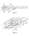
- Such beams 10 and the associated formwork elements 100 are illustrated in FIGS. Figures 12, 13 and 14 .
- the beams 10 may in particular be placed between the floor 1 of the floor and the floor 2 of the balcony.
- the shuttering elements 100 may further comprise, on their lateral walls 150, through orifices 301 adapted to receive transverse reinforcing rods 300 adapted to pass through the shuttering element on either side. 100 corresponding.
- transverse reinforcement bars 300 are intended to form strands for the beam 10 according to the invention, and thus resume the forces exerted on the beam 10 and the corresponding formwork elements 100.
- they are preferably made of composite material, in order to promote a high thermal insulation of the constructions.
- Such beams 10 may be self-supporting or simply placed on the floor 1.
- the reinforcing bars 300 are, moreover, embedded in the floor 1 and the floor 2 of the balcony.
- Such beams 10 may be self-supporting or simply placed on the floor 1.
- At least two end-to-end shuttering elements 100 can be configured to be installed on a wall screed 400 or a construction element, such as a concrete block, and to support a beam 10, as illustrated in FIG. figure 11 .
- a platinum or transverse reinforcement bar 300 may be configured to be connected to a recess 152 of a formwork element.
- Each shuttering element 100 may have side walls of different heights.
- Such an embodiment makes it possible to cast a compression table at the same time as a belt.
Landscapes
- Engineering & Computer Science (AREA)
- Architecture (AREA)
- Civil Engineering (AREA)
- Structural Engineering (AREA)
- Forms Removed On Construction Sites Or Auxiliary Members Thereof (AREA)
Applications Claiming Priority (1)
| Application Number | Priority Date | Filing Date | Title |
|---|---|---|---|
| FR1000496A FR2956139B1 (fr) | 2010-02-08 | 2010-02-08 | Element de coffrage pour la construction d'une poutrelle |
Publications (2)
| Publication Number | Publication Date |
|---|---|
| EP2444567A1 true EP2444567A1 (de) | 2012-04-25 |
| EP2444567B1 EP2444567B1 (de) | 2021-01-13 |
Family
ID=43033121
Family Applications (1)
| Application Number | Title | Priority Date | Filing Date |
|---|---|---|---|
| EP11153695.9A Active EP2444567B1 (de) | 2010-02-08 | 2011-02-08 | Verschalungselement zum Bau eines Trägers |
Country Status (2)
| Country | Link |
|---|---|
| EP (1) | EP2444567B1 (de) |
| FR (1) | FR2956139B1 (de) |
Cited By (1)
| Publication number | Priority date | Publication date | Assignee | Title |
|---|---|---|---|---|
| CN117569506A (zh) * | 2023-12-01 | 2024-02-20 | 晟通科技集团有限公司 | 一种底模可拆卸的钢筋桁架楼承板及施工方法 |
Families Citing this family (1)
| Publication number | Priority date | Publication date | Assignee | Title |
|---|---|---|---|---|
| CN114150864B (zh) * | 2021-12-02 | 2023-01-31 | 浙江银晨建设有限公司 | 一种大跨度预应力混凝土梁支模结构 |
Citations (4)
| Publication number | Priority date | Publication date | Assignee | Title |
|---|---|---|---|---|
| EP0870883A2 (de) * | 1997-04-11 | 1998-10-14 | Gruppo Effe 2 SpA | Vorgefertigte Balken für Decken und/oder aus einem Gitter und Ziegeln hergestellter Verblendsturz, und Ziegel dafür |
| EP1398427A1 (de) * | 2002-09-11 | 2004-03-17 | Ezio Ferrari | Element zum Positionieren von Bewehrungen in einem Betonträger |
| DE20309363U1 (de) * | 2003-06-17 | 2004-07-22 | Filigran Trägersysteme GmbH & Co KG | Bauelement |
| EP1967667A1 (de) * | 2007-03-07 | 2008-09-10 | CSR limited | Dachziegel |
Family Cites Families (2)
| Publication number | Priority date | Publication date | Assignee | Title |
|---|---|---|---|---|
| GB2077792B (en) * | 1980-03-22 | 1983-06-08 | Tinsley Building Prod Ltd | Casting reinforced concrete floors |
| FR2940337B1 (fr) * | 2008-12-19 | 2010-12-31 | Isoltop | Poutrelle metallique pour la fabrication de planchers |
-
2010
- 2010-02-08 FR FR1000496A patent/FR2956139B1/fr active Active
-
2011
- 2011-02-08 EP EP11153695.9A patent/EP2444567B1/de active Active
Patent Citations (4)
| Publication number | Priority date | Publication date | Assignee | Title |
|---|---|---|---|---|
| EP0870883A2 (de) * | 1997-04-11 | 1998-10-14 | Gruppo Effe 2 SpA | Vorgefertigte Balken für Decken und/oder aus einem Gitter und Ziegeln hergestellter Verblendsturz, und Ziegel dafür |
| EP1398427A1 (de) * | 2002-09-11 | 2004-03-17 | Ezio Ferrari | Element zum Positionieren von Bewehrungen in einem Betonträger |
| DE20309363U1 (de) * | 2003-06-17 | 2004-07-22 | Filigran Trägersysteme GmbH & Co KG | Bauelement |
| EP1967667A1 (de) * | 2007-03-07 | 2008-09-10 | CSR limited | Dachziegel |
Cited By (1)
| Publication number | Priority date | Publication date | Assignee | Title |
|---|---|---|---|---|
| CN117569506A (zh) * | 2023-12-01 | 2024-02-20 | 晟通科技集团有限公司 | 一种底模可拆卸的钢筋桁架楼承板及施工方法 |
Also Published As
| Publication number | Publication date |
|---|---|
| EP2444567B1 (de) | 2021-01-13 |
| FR2956139B1 (fr) | 2012-02-24 |
| FR2956139A1 (fr) | 2011-08-12 |
Similar Documents
| Publication | Publication Date | Title |
|---|---|---|
| FR2985750A1 (fr) | Element de construction modulaire prefabrique pour la realisation de mur | |
| EP2444567B1 (de) | Verschalungselement zum Bau eines Trägers | |
| FR2922916A1 (fr) | Element modulaire prefabrique de plancher sec, procede de fabrication d'un tel element modulaire et plancher sec constitue d'une pluralite d'elements modulaires. | |
| EP0174882B1 (de) | Wärmedämmender Schalungsstein | |
| FR2995330A1 (fr) | Predalle en beton pour construction de plancher de batiment | |
| EP3070221B1 (de) | Verfahren zur behandlung von wärmebrücken, entsprechendes wärmeisolationselement und entsprechendes strukturelles verbindungselement sowie mit diesen elementen ausgerüstete schal-betonplatte | |
| FR2575778A1 (fr) | Element de construction prefabrique et procede pour la realisation d'un mur isotherme | |
| FR2927645A1 (fr) | Coffre-tunnel bi-matiere pour volet roulant | |
| FR2939817A1 (fr) | Bloc elementaire prefabrique pour la construction d'un mur a isolation exterieure | |
| EP3070220B1 (de) | Verfahren zur behandlung von wärmebrücken | |
| FR2507647A1 (fr) | Panneau de construction prefabrique et procede pour la realisation d'un tel panneau | |
| FR2861767A1 (fr) | Rupteur thermique pour plancher en beton, dalle prefabriquee equipee d'un tel rupteur thermique et procede de fabrication d'un plancher | |
| EP3309312A1 (de) | Verfahren zur herstellung von balkon und so gewonnener balkon | |
| WO2011151605A2 (fr) | Element de construction a base de carton et procede de construction a l'aide de tels elements | |
| EP1943395B1 (de) | Isolierschalung für betonwände | |
| EP3070222B1 (de) | Fertigbauelement und herstellungsverfahren eines solchen fertigbauelements | |
| BE1025884B1 (fr) | Procede de fabrication d'un mur interieur et mur interieur obtenu | |
| EP2844809A1 (de) | Schalung und entsprechender boden | |
| EP2464798B1 (de) | Vorgefertigtes bauelement, zur vermeidung von wärmebrücken | |
| FR3075837A1 (fr) | Procede de fabrication d'un plancher a rupture de pont thermique, support de reception pour rupteur thermique et plancher a rupture de pont thermique obtenu | |
| FR3031532A1 (fr) | Systemes d'isolation thermique utilises en particulier pour realiser des murs/parois de batiments isoles thermiquement. | |
| EP3320155A1 (de) | Ankervorrichtung und ankeranordnung mit zwei solcher vorrichtungen | |
| WO2016132195A1 (fr) | Element de construction et procede de montage d'un tel element de construction | |
| EP2784236B1 (de) | Wandstrukturelement | |
| WO2017006160A1 (fr) | Element de construction et procede de montage d'un tel element de construction |
Legal Events
| Date | Code | Title | Description |
|---|---|---|---|
| AK | Designated contracting states |
Kind code of ref document: A1 Designated state(s): AL AT BE BG CH CY CZ DE DK EE ES FI FR GB GR HR HU IE IS IT LI LT LU LV MC MK MT NL NO PL PT RO RS SE SI SK SM TR |
|
| AX | Request for extension of the european patent |
Extension state: BA ME |
|
| PUAI | Public reference made under article 153(3) epc to a published international application that has entered the european phase |
Free format text: ORIGINAL CODE: 0009012 |
|
| 17P | Request for examination filed |
Effective date: 20121009 |
|
| 17Q | First examination report despatched |
Effective date: 20160805 |
|
| STAA | Information on the status of an ep patent application or granted ep patent |
Free format text: STATUS: EXAMINATION IS IN PROGRESS |
|
| GRAP | Despatch of communication of intention to grant a patent |
Free format text: ORIGINAL CODE: EPIDOSNIGR1 |
|
| STAA | Information on the status of an ep patent application or granted ep patent |
Free format text: STATUS: GRANT OF PATENT IS INTENDED |
|
| INTG | Intention to grant announced |
Effective date: 20200624 |
|
| GRAJ | Information related to disapproval of communication of intention to grant by the applicant or resumption of examination proceedings by the epo deleted |
Free format text: ORIGINAL CODE: EPIDOSDIGR1 |
|
| STAA | Information on the status of an ep patent application or granted ep patent |
Free format text: STATUS: EXAMINATION IS IN PROGRESS |
|
| INTC | Intention to grant announced (deleted) | ||
| GRAP | Despatch of communication of intention to grant a patent |
Free format text: ORIGINAL CODE: EPIDOSNIGR1 |
|
| STAA | Information on the status of an ep patent application or granted ep patent |
Free format text: STATUS: GRANT OF PATENT IS INTENDED |
|
| INTG | Intention to grant announced |
Effective date: 20201002 |
|
| GRAS | Grant fee paid |
Free format text: ORIGINAL CODE: EPIDOSNIGR3 |
|
| GRAA | (expected) grant |
Free format text: ORIGINAL CODE: 0009210 |
|
| STAA | Information on the status of an ep patent application or granted ep patent |
Free format text: STATUS: THE PATENT HAS BEEN GRANTED |
|
| AK | Designated contracting states |
Kind code of ref document: B1 Designated state(s): AL AT BE BG CH CY CZ DE DK EE ES FI FR GB GR HR HU IE IS IT LI LT LU LV MC MK MT NL NO PL PT RO RS SE SI SK SM TR |
|
| REG | Reference to a national code |
Ref country code: GB Ref legal event code: FG4D Free format text: NOT ENGLISH |
|
| REG | Reference to a national code |
Ref country code: CH Ref legal event code: EP |
|
| REG | Reference to a national code |
Ref country code: IE Ref legal event code: FG4D Free format text: LANGUAGE OF EP DOCUMENT: FRENCH |
|
| REG | Reference to a national code |
Ref country code: DE Ref legal event code: R096 Ref document number: 602011069941 Country of ref document: DE |
|
| REG | Reference to a national code |
Ref country code: AT Ref legal event code: REF Ref document number: 1354670 Country of ref document: AT Kind code of ref document: T Effective date: 20210215 |
|
| REG | Reference to a national code |
Ref country code: CH Ref legal event code: NV Representative=s name: CABINET GERMAIN AND MAUREAU, CH |
|
| REG | Reference to a national code |
Ref country code: AT Ref legal event code: MK05 Ref document number: 1354670 Country of ref document: AT Kind code of ref document: T Effective date: 20210113 |
|
| REG | Reference to a national code |
Ref country code: NL Ref legal event code: MP Effective date: 20210113 |
|
| REG | Reference to a national code |
Ref country code: LT Ref legal event code: MG9D |
|
| PG25 | Lapsed in a contracting state [announced via postgrant information from national office to epo] |
Ref country code: BG Free format text: LAPSE BECAUSE OF FAILURE TO SUBMIT A TRANSLATION OF THE DESCRIPTION OR TO PAY THE FEE WITHIN THE PRESCRIBED TIME-LIMIT Effective date: 20210413 Ref country code: NO Free format text: LAPSE BECAUSE OF FAILURE TO SUBMIT A TRANSLATION OF THE DESCRIPTION OR TO PAY THE FEE WITHIN THE PRESCRIBED TIME-LIMIT Effective date: 20210413 Ref country code: NL Free format text: LAPSE BECAUSE OF FAILURE TO SUBMIT A TRANSLATION OF THE DESCRIPTION OR TO PAY THE FEE WITHIN THE PRESCRIBED TIME-LIMIT Effective date: 20210113 Ref country code: PT Free format text: LAPSE BECAUSE OF FAILURE TO SUBMIT A TRANSLATION OF THE DESCRIPTION OR TO PAY THE FEE WITHIN THE PRESCRIBED TIME-LIMIT Effective date: 20210513 Ref country code: HR Free format text: LAPSE BECAUSE OF FAILURE TO SUBMIT A TRANSLATION OF THE DESCRIPTION OR TO PAY THE FEE WITHIN THE PRESCRIBED TIME-LIMIT Effective date: 20210113 Ref country code: GR Free format text: LAPSE BECAUSE OF FAILURE TO SUBMIT A TRANSLATION OF THE DESCRIPTION OR TO PAY THE FEE WITHIN THE PRESCRIBED TIME-LIMIT Effective date: 20210414 Ref country code: FI Free format text: LAPSE BECAUSE OF FAILURE TO SUBMIT A TRANSLATION OF THE DESCRIPTION OR TO PAY THE FEE WITHIN THE PRESCRIBED TIME-LIMIT Effective date: 20210113 Ref country code: LT Free format text: LAPSE BECAUSE OF FAILURE TO SUBMIT A TRANSLATION OF THE DESCRIPTION OR TO PAY THE FEE WITHIN THE PRESCRIBED TIME-LIMIT Effective date: 20210113 |
|
| PG25 | Lapsed in a contracting state [announced via postgrant information from national office to epo] |
Ref country code: SE Free format text: LAPSE BECAUSE OF FAILURE TO SUBMIT A TRANSLATION OF THE DESCRIPTION OR TO PAY THE FEE WITHIN THE PRESCRIBED TIME-LIMIT Effective date: 20210113 Ref country code: AT Free format text: LAPSE BECAUSE OF FAILURE TO SUBMIT A TRANSLATION OF THE DESCRIPTION OR TO PAY THE FEE WITHIN THE PRESCRIBED TIME-LIMIT Effective date: 20210113 Ref country code: PL Free format text: LAPSE BECAUSE OF FAILURE TO SUBMIT A TRANSLATION OF THE DESCRIPTION OR TO PAY THE FEE WITHIN THE PRESCRIBED TIME-LIMIT Effective date: 20210113 Ref country code: RS Free format text: LAPSE BECAUSE OF FAILURE TO SUBMIT A TRANSLATION OF THE DESCRIPTION OR TO PAY THE FEE WITHIN THE PRESCRIBED TIME-LIMIT Effective date: 20210113 Ref country code: LV Free format text: LAPSE BECAUSE OF FAILURE TO SUBMIT A TRANSLATION OF THE DESCRIPTION OR TO PAY THE FEE WITHIN THE PRESCRIBED TIME-LIMIT Effective date: 20210113 |
|
| PG25 | Lapsed in a contracting state [announced via postgrant information from national office to epo] |
Ref country code: IS Free format text: LAPSE BECAUSE OF FAILURE TO SUBMIT A TRANSLATION OF THE DESCRIPTION OR TO PAY THE FEE WITHIN THE PRESCRIBED TIME-LIMIT Effective date: 20210513 |
|
| REG | Reference to a national code |
Ref country code: DE Ref legal event code: R097 Ref document number: 602011069941 Country of ref document: DE |
|
| PG25 | Lapsed in a contracting state [announced via postgrant information from national office to epo] |
Ref country code: SM Free format text: LAPSE BECAUSE OF FAILURE TO SUBMIT A TRANSLATION OF THE DESCRIPTION OR TO PAY THE FEE WITHIN THE PRESCRIBED TIME-LIMIT Effective date: 20210113 Ref country code: EE Free format text: LAPSE BECAUSE OF FAILURE TO SUBMIT A TRANSLATION OF THE DESCRIPTION OR TO PAY THE FEE WITHIN THE PRESCRIBED TIME-LIMIT Effective date: 20210113 Ref country code: CZ Free format text: LAPSE BECAUSE OF FAILURE TO SUBMIT A TRANSLATION OF THE DESCRIPTION OR TO PAY THE FEE WITHIN THE PRESCRIBED TIME-LIMIT Effective date: 20210113 |
|
| PLBE | No opposition filed within time limit |
Free format text: ORIGINAL CODE: 0009261 |
|
| STAA | Information on the status of an ep patent application or granted ep patent |
Free format text: STATUS: NO OPPOSITION FILED WITHIN TIME LIMIT |
|
| PG25 | Lapsed in a contracting state [announced via postgrant information from national office to epo] |
Ref country code: RO Free format text: LAPSE BECAUSE OF FAILURE TO SUBMIT A TRANSLATION OF THE DESCRIPTION OR TO PAY THE FEE WITHIN THE PRESCRIBED TIME-LIMIT Effective date: 20210113 Ref country code: SK Free format text: LAPSE BECAUSE OF FAILURE TO SUBMIT A TRANSLATION OF THE DESCRIPTION OR TO PAY THE FEE WITHIN THE PRESCRIBED TIME-LIMIT Effective date: 20210113 Ref country code: ES Free format text: LAPSE BECAUSE OF FAILURE TO SUBMIT A TRANSLATION OF THE DESCRIPTION OR TO PAY THE FEE WITHIN THE PRESCRIBED TIME-LIMIT Effective date: 20210113 Ref country code: DK Free format text: LAPSE BECAUSE OF FAILURE TO SUBMIT A TRANSLATION OF THE DESCRIPTION OR TO PAY THE FEE WITHIN THE PRESCRIBED TIME-LIMIT Effective date: 20210113 |
|
| 26N | No opposition filed |
Effective date: 20211014 |
|
| PG25 | Lapsed in a contracting state [announced via postgrant information from national office to epo] |
Ref country code: AL Free format text: LAPSE BECAUSE OF FAILURE TO SUBMIT A TRANSLATION OF THE DESCRIPTION OR TO PAY THE FEE WITHIN THE PRESCRIBED TIME-LIMIT Effective date: 20210113 Ref country code: IE Free format text: LAPSE BECAUSE OF NON-PAYMENT OF DUE FEES Effective date: 20210208 |
|
| PG25 | Lapsed in a contracting state [announced via postgrant information from national office to epo] |
Ref country code: SI Free format text: LAPSE BECAUSE OF FAILURE TO SUBMIT A TRANSLATION OF THE DESCRIPTION OR TO PAY THE FEE WITHIN THE PRESCRIBED TIME-LIMIT Effective date: 20210113 |
|
| PG25 | Lapsed in a contracting state [announced via postgrant information from national office to epo] |
Ref country code: IS Free format text: LAPSE BECAUSE OF FAILURE TO SUBMIT A TRANSLATION OF THE DESCRIPTION OR TO PAY THE FEE WITHIN THE PRESCRIBED TIME-LIMIT Effective date: 20210513 |
|
| PG25 | Lapsed in a contracting state [announced via postgrant information from national office to epo] |
Ref country code: HU Free format text: LAPSE BECAUSE OF FAILURE TO SUBMIT A TRANSLATION OF THE DESCRIPTION OR TO PAY THE FEE WITHIN THE PRESCRIBED TIME-LIMIT; INVALID AB INITIO Effective date: 20110208 Ref country code: CY Free format text: LAPSE BECAUSE OF FAILURE TO SUBMIT A TRANSLATION OF THE DESCRIPTION OR TO PAY THE FEE WITHIN THE PRESCRIBED TIME-LIMIT Effective date: 20210113 |
|
| PGFP | Annual fee paid to national office [announced via postgrant information from national office to epo] |
Ref country code: LU Payment date: 20240227 Year of fee payment: 14 |
|
| PGFP | Annual fee paid to national office [announced via postgrant information from national office to epo] |
Ref country code: MC Payment date: 20240222 Year of fee payment: 14 |
|
| PG25 | Lapsed in a contracting state [announced via postgrant information from national office to epo] |
Ref country code: MK Free format text: LAPSE BECAUSE OF FAILURE TO SUBMIT A TRANSLATION OF THE DESCRIPTION OR TO PAY THE FEE WITHIN THE PRESCRIBED TIME-LIMIT Effective date: 20210113 |
|
| PGFP | Annual fee paid to national office [announced via postgrant information from national office to epo] |
Ref country code: DE Payment date: 20240219 Year of fee payment: 14 Ref country code: CH Payment date: 20240301 Year of fee payment: 14 Ref country code: GB Payment date: 20240219 Year of fee payment: 14 |
|
| PG25 | Lapsed in a contracting state [announced via postgrant information from national office to epo] |
Ref country code: MT Free format text: LAPSE BECAUSE OF FAILURE TO SUBMIT A TRANSLATION OF THE DESCRIPTION OR TO PAY THE FEE WITHIN THE PRESCRIBED TIME-LIMIT Effective date: 20210113 |
|
| PGFP | Annual fee paid to national office [announced via postgrant information from national office to epo] |
Ref country code: BE Payment date: 20250225 Year of fee payment: 15 |
|
| PGFP | Annual fee paid to national office [announced via postgrant information from national office to epo] |
Ref country code: IT Payment date: 20250225 Year of fee payment: 15 |
|
| REG | Reference to a national code |
Ref country code: DE Ref legal event code: R119 Ref document number: 602011069941 Country of ref document: DE |
|
| PG25 | Lapsed in a contracting state [announced via postgrant information from national office to epo] |
Ref country code: MC Free format text: LAPSE BECAUSE OF NON-PAYMENT OF DUE FEES Effective date: 20250228 |
|
| REG | Reference to a national code |
Ref country code: CH Ref legal event code: PL |
|
| PG25 | Lapsed in a contracting state [announced via postgrant information from national office to epo] |
Ref country code: LU Free format text: LAPSE BECAUSE OF NON-PAYMENT OF DUE FEES Effective date: 20250208 |
|
| PG25 | Lapsed in a contracting state [announced via postgrant information from national office to epo] |
Ref country code: CH Free format text: LAPSE BECAUSE OF NON-PAYMENT OF DUE FEES Effective date: 20250228 |
|
| GBPC | Gb: european patent ceased through non-payment of renewal fee |
Effective date: 20250208 |
|
| PG25 | Lapsed in a contracting state [announced via postgrant information from national office to epo] |
Ref country code: TR Free format text: LAPSE BECAUSE OF FAILURE TO SUBMIT A TRANSLATION OF THE DESCRIPTION OR TO PAY THE FEE WITHIN THE PRESCRIBED TIME-LIMIT Effective date: 20210113 |
|
| PG25 | Lapsed in a contracting state [announced via postgrant information from national office to epo] |
Ref country code: DE Free format text: LAPSE BECAUSE OF NON-PAYMENT OF DUE FEES Effective date: 20250902 |
|
| PG25 | Lapsed in a contracting state [announced via postgrant information from national office to epo] |
Ref country code: GB Free format text: LAPSE BECAUSE OF NON-PAYMENT OF DUE FEES Effective date: 20250208 |
|
| PGFP | Annual fee paid to national office [announced via postgrant information from national office to epo] |
Ref country code: FR Payment date: 20260227 Year of fee payment: 16 |