EP0870903A2 - Akustisch verbesserte Anordung von Gasturbinenschaufeln - Google Patents
Akustisch verbesserte Anordung von Gasturbinenschaufeln Download PDFInfo
- Publication number
- EP0870903A2 EP0870903A2 EP98302801A EP98302801A EP0870903A2 EP 0870903 A2 EP0870903 A2 EP 0870903A2 EP 98302801 A EP98302801 A EP 98302801A EP 98302801 A EP98302801 A EP 98302801A EP 0870903 A2 EP0870903 A2 EP 0870903A2
- Authority
- EP
- European Patent Office
- Prior art keywords
- blades
- uniformity
- circumferential
- harmonics
- hub
- Prior art date
- Legal status (The legal status is an assumption and is not a legal conclusion. Google has not performed a legal analysis and makes no representation as to the accuracy of the status listed.)
- Granted
Links
- 238000001228 spectrum Methods 0.000 claims abstract description 54
- 238000000034 method Methods 0.000 claims description 13
- 230000008859 change Effects 0.000 claims description 2
- 230000000737 periodic effect Effects 0.000 claims description 2
- 230000000116 mitigating effect Effects 0.000 abstract description 9
- 238000009826 distribution Methods 0.000 description 44
- 230000035939 shock Effects 0.000 description 17
- 238000004519 manufacturing process Methods 0.000 description 7
- 239000003570 air Substances 0.000 description 6
- 238000003491 array Methods 0.000 description 6
- 238000009987 spinning Methods 0.000 description 6
- 239000000463 material Substances 0.000 description 4
- 230000003595 spectral effect Effects 0.000 description 4
- 238000010586 diagram Methods 0.000 description 3
- 230000000694 effects Effects 0.000 description 3
- 230000001902 propagating effect Effects 0.000 description 3
- 230000007704 transition Effects 0.000 description 3
- 230000005484 gravity Effects 0.000 description 2
- 238000009434 installation Methods 0.000 description 2
- 230000009467 reduction Effects 0.000 description 2
- 238000011144 upstream manufacturing Methods 0.000 description 2
- 230000001154 acute effect Effects 0.000 description 1
- 239000012080 ambient air Substances 0.000 description 1
- 238000004458 analytical method Methods 0.000 description 1
- 230000003466 anti-cipated effect Effects 0.000 description 1
- 230000001066 destructive effect Effects 0.000 description 1
- 230000001747 exhibiting effect Effects 0.000 description 1
- 238000007689 inspection Methods 0.000 description 1
- 230000003993 interaction Effects 0.000 description 1
- 230000014759 maintenance of location Effects 0.000 description 1
Images






Classifications
-
- F—MECHANICAL ENGINEERING; LIGHTING; HEATING; WEAPONS; BLASTING
- F04—POSITIVE - DISPLACEMENT MACHINES FOR LIQUIDS; PUMPS FOR LIQUIDS OR ELASTIC FLUIDS
- F04D—NON-POSITIVE-DISPLACEMENT PUMPS
- F04D29/00—Details, component parts, or accessories
- F04D29/66—Combating cavitation, whirls, noise, vibration or the like; Balancing
- F04D29/661—Combating cavitation, whirls, noise, vibration or the like; Balancing especially adapted for elastic fluid pumps
- F04D29/666—Combating cavitation, whirls, noise, vibration or the like; Balancing especially adapted for elastic fluid pumps by means of rotor construction or layout, e.g. unequal distribution of blades or vanes
-
- F—MECHANICAL ENGINEERING; LIGHTING; HEATING; WEAPONS; BLASTING
- F01—MACHINES OR ENGINES IN GENERAL; ENGINE PLANTS IN GENERAL; STEAM ENGINES
- F01D—NON-POSITIVE DISPLACEMENT MACHINES OR ENGINES, e.g. STEAM TURBINES
- F01D5/00—Blades; Blade-carrying members; Heating, heat-insulating, cooling or antivibration means on the blades or the members
- F01D5/02—Blade-carrying members, e.g. rotors
- F01D5/06—Rotors for more than one axial stage, e.g. of drum or multiple disc type; Details thereof, e.g. shafts, shaft connections
-
- F—MECHANICAL ENGINEERING; LIGHTING; HEATING; WEAPONS; BLASTING
- F01—MACHINES OR ENGINES IN GENERAL; ENGINE PLANTS IN GENERAL; STEAM ENGINES
- F01D—NON-POSITIVE DISPLACEMENT MACHINES OR ENGINES, e.g. STEAM TURBINES
- F01D5/00—Blades; Blade-carrying members; Heating, heat-insulating, cooling or antivibration means on the blades or the members
- F01D5/02—Blade-carrying members, e.g. rotors
- F01D5/10—Anti- vibration means
-
- F—MECHANICAL ENGINEERING; LIGHTING; HEATING; WEAPONS; BLASTING
- F05—INDEXING SCHEMES RELATING TO ENGINES OR PUMPS IN VARIOUS SUBCLASSES OF CLASSES F01-F04
- F05D—INDEXING SCHEME FOR ASPECTS RELATING TO NON-POSITIVE-DISPLACEMENT MACHINES OR ENGINES, GAS-TURBINES OR JET-PROPULSION PLANTS
- F05D2260/00—Function
- F05D2260/96—Preventing, counteracting or reducing vibration or noise
-
- Y—GENERAL TAGGING OF NEW TECHNOLOGICAL DEVELOPMENTS; GENERAL TAGGING OF CROSS-SECTIONAL TECHNOLOGIES SPANNING OVER SEVERAL SECTIONS OF THE IPC; TECHNICAL SUBJECTS COVERED BY FORMER USPC CROSS-REFERENCE ART COLLECTIONS [XRACs] AND DIGESTS
- Y02—TECHNOLOGIES OR APPLICATIONS FOR MITIGATION OR ADAPTATION AGAINST CLIMATE CHANGE
- Y02T—CLIMATE CHANGE MITIGATION TECHNOLOGIES RELATED TO TRANSPORTATION
- Y02T50/00—Aeronautics or air transport
- Y02T50/60—Efficient propulsion technologies, e.g. for aircraft
Definitions
- This invention pertains to the mitigation of combination tone noise emitted by a rotating blade array, particularly the rotating fan blade array of a gas turbine engine.
- Gas turbine engines of the type used for aircraft propulsion include a fan rotor which comprises an array of fan blades recessed within an engine intake duct and projecting radially outwardly from a central hub.
- the hub and blades rotate about a longitudinally extending axis to pressurize a stream of air flowing through the duct.
- the radially outermost portions of the fan blades operate supersonically so that the leading edge of each blade generates an aerodynamic shock. These shocks propagate forwardly, i.e. opposite to the direction of flow of the air stream, and exit from the intake duct.
- each blade in the array differs slightly from the other blades in the array due to allowable manufacturing and installation tolerances. Because of these blade-to-blade non-uniformities, the shocks are non-uniformly oriented and propagate at different speeds. As a result, the shocks interact within the intake duct to produce a complex, time varying air pressure pattern which repeats once per rotor revolution.
- the frequency spectrum of this pressure pattern includes a fundamental frequency of once per fan rotor revolution as well as multiple higher order harmonics of the fundamental frequency.
- the noise associated with the pressure pattern is known as combination tone noise or multiple pure tone noise and, when it propagates forwardly beyond the confines of the intake duct, can be objectionable to airplane cabin occupants and to residents of communities in the vicinity of airports.
- Combination tone noise is likely to become an increasingly prevalent problem since the fans of modern engines have a larger diameter than those of earlier generation engines and therefore operate at slower rotational speeds. In addition, modern engines often employ fewer fan blades than earlier generation engines. Both of these trends, slower rotational speeds and reduced blade quantity, result in the acoustic energy of the combination tone noise being concentrated at lower frequencies. Since acoustic energy at low frequencies is less readily attenuable than acoustic energy at high frequencies, current trends in the gas turbine industry appear likely to exacerbate the problem of combination tone noise.
- One possible way to address the problem of combination tone noise is to employ sound attenuating material in the fuselage of the aircraft to shield occupants from the noise.
- sound attenuating material adds cost and weight to the aircraft and can be difficult to incorporate if the need for the material was not anticipated early in the design of the aircraft.
- the use of sound attenuating material in the aircraft does nothing to alleviate the community noise problem.
- Minimization of blade to blade non-uniformity might also be achieved by carefully selecting a subset of nearly uniform blades from a larger set of less uniform blades.
- This approach relies on the presence of a sufficiently large inventory of blades from which the subset can be selected.
- An engine manufacturer is unlikely to possess such an inventory, and an engine owner, who may be faced with the occasional need to replace several damaged blades in a rotor, is almost certain not to possess an adequate inventory. Even if such an inventory was available, the requirement to select a nearly uniform subset of blades slows the pace of assembly operations and, without additional selection criteria, introduces the possibility of flutter referred to above.
- This invention is based in part on the recognition that the frequency spectrum of combination tone noise includes low order, decay prone harmonics which decay within the engine intake duct as well as higher order, decay resistant harmonics which propagate beyond the duct, and that significant mitigation of combination tone noise is achievable by forcing acoustic energy out of the decay resistant harmonics and into the decay prone harmonics.
- the invention is further based in part on the recognition that a population of fan blades, which exhibit physical non-uniformities, can be distributed in a hub to effect the aforementioned allocation of acoustic energy among the combination tone noise harmonics.
- the invention provides a bladed rotor for a turbine engine, the rotor including a hub rotatable about a longitudinally extending axis and a population of blades circumferentially distributed in the hub at discrete angular locations and extending from the hub, the blades having at least one circumferentially varying physical non-uniformity which contributes to combination tone noise, the combination tone noise having a noise frequency spectrum one of whose harmonics is a cutoff harmonic of order n , n being a positive integer, the variation of each physical non-uniformity with respect to angular location having a circumferential non-uniformity spectrum, the rotor characterized in that the blades are distributed in the hub so that each circumferential non-uniformity spectrum is dominated by circumferential harmonics of order no greater than q , q being an integer specific to each non-uniformity and no greater than n so that the combination tone noise is mitigated.
- the invention provides a method of minimizing combination tone noise generated by a bladed rotor having a hub, which is rotatable about a longitudinally extending central axis, and a population of blades circumferentially distributed in the hub at discrete angular locations and extending from the hub, the blades having at least one circumferentially varying physical non-uniformity which contributes to combination tone noise, the combination tone noise having a noise frequency spectrum one of whose harmonics is a cutoff harmonic of order n , n being a positive integer, the method characterized by:
- a population of fan blades that exhibits a physical blade-to-blade non-uniformity is distributed in a hub so that the circumferential spectrum of the non-uniformity is dominated by circumferential harmonics whose order does not exceed that of the highest order decay prone harmonic of the combination tone noise frequency spectrum.
- the invention may be seen as providing an array of turbine blades for a gas turbine engine circumferentially distributed about an axis, wherein the order of the blades around the axis is selected to give a periodic variation in a physical non-uniformity between the blades.
- the physical non-uniformity is the leading edge pitch angle of the blades and the circumferential non-uniformity spectrum is dominated by circumferential harmonics of order no greater than two.
- the dominance of desirable, low order circumferential harmonics is effected by distributing the blades so that a weighted sum of the amplitudes of the undesirable, higher order circumferential harmonics is no greater than a specified threshold.
- the invention is advantageous in that it defeats combination tone noise at its source, and therefore addresses both community noise concerns and airplane cabin noise concerns. Because the invention relies on the judicious distribution of blades rather than on stringent manufacturing tolerances, it is cost effective and is applicable to existing blade arrays as well as newly assembled blade arrays. Moreover, because the invention manipulates the circumferential spectrum of the physical non-uniformity rather than attempting to minimize the non-uniformity, there is little accompanying risk of fan flutter.
- Figure 1 is a cross sectional schematic side view of a gas turbine engine having a fan blade array and housed within an aerodynamically streamlined nacelle.
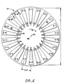
- Figure 2 is a view taken in the direction 2--2 of Fig. 1 showing the fan blade array with the blades distributed in accordance with the present invention.
- Figures 3A, 3B and 3C are, respectively, a schematic, developed view of a portion of an ideal fan blade array showing aerodynamic shocks generated by each blade, a graph of a pressure signal associated with the shocks and a spectral diagram showing the frequency spectrum of the pressure signal.
- Figures 4A, 4B and 4C are, respectively, a schematic, developed view of a portion of a fan blade array having blade-to-blade non-uniformities and showing aerodynamic shocks generated by each blade, a graph of a pressure signal associated with the shocks and a spectral diagram showing the frequency spectrum of the pressure signal.
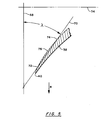
- Figure 5 is a cross sectional view of the leading edge region of a fan blade taken in the direction 5--5 of Fig. 2 and illustrating the definition of leading edge stagger angle, ⁇ .
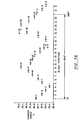
- Figure 6 is a table illustrating the stagger angle of a population of fan blades and showing the positions of those blades in a fan hub in accordance with the present invention and according to the prior art.
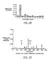
- Figures 7A, 7B and 7C are, respectively, a graph showing fan blade stagger angle versus circumferential position for a population of blades distributed in a hub, the circumferential spectrum of the stagger angle distribution and the frequency spectrum of combination tone noise emitted by the blade population during engine operation.
- Figures 8A, 8B and 8C are, respectively, a graph showing fan blade stagger angle versus circumferential position for a population of blades distributed in a hub according to the prior art, the circumferential spectrum of the stagger angle distribution and the frequency spectrum of combination tone noise emitted by the blade population during engine operation.
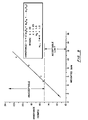
- Figure 9 is a graph showing noise as a function of a weighted sum of the circumferential harmonics of a stagger angle distribution.
- an aircraft gas turbine engine 30 includes a fan rotor 32 rotatable about a longitudinally extending axis 34.
- the fan rotor includes a fan blade array 36 comprising a population of twenty two blades 38 individually designated by letters B 1 through B 22 .
- Each blade has a leading edge 40 and a trailing edge 42 and is secured in one of twenty two retaining slots 46, individually numbered 1 through 22, in a rotor hub 48.
- the fan rotor has a diameter D which is the distance from a blade tip to the diametrically opposite blade tip.
- the engine is housed in an aerodynamically streamlined nacelle 52, the forward portion of which is an inlet 54 having a lip 56 at its forwardmost extremity.
- the inlet bounds an intake duct 58 and the engine is positioned within the nacelle so that the leading edge of the fan blade array is recessed within the duct by a longitudinal distance d , the distance from the lip to the array leading edge.
- the fan rotor rotates about the axis in direction R at a speed N which varies in accordance with the power demands placed on the engine.
- the rotor rotation and forward velocity of the engine cause ambient air 62 to enter the intake duct and flow through the fan blade array which pressurizes the air for use by other engine components.
- the air has a Mach Number component M x in the longitudinal direction and is capable of propagating sound or pressure waves at a sonic velocity c.
- the radially outermost portions of the fan blades operate supersonically so that the leading edge of each blade generates an aerodynamic shock.
- each blade as installed in the hub, is ideally identical to every other blade. That is, there are no differences in any physical attributes of the blades 38, such as their shape, position or orientation, that would affect the uniformity of shocks 66 generated near the blade tips. As a result, the shocks 66 are uniformly oriented. Moreover the shocks are of uniform strength and therefore propagate at the same speed. Therefore, an observer positioned forwardly of the blade array perceives a time varying pressure or noise signal, as shown in Fig 3B, as the propagating shocks arrive at the observer's position.
- the frequency spectrum of the noise signal includes a fundamental frequency equal to the blade passing frequency BPF (i.e. the rate at which fan blades pass an arbitrary angular reference point) and higher order harmonics (integral multiples) of the blade passing frequency.
- BPF blade passing frequency
- Figure 4A illustrates a blade array exhibiting a number of blade-to-blade physical non-uniformities. These non-uniformities, which are highly exaggerated in the illustration, include differences in the blade leading edge position ⁇ x, blade angular offset ⁇ (seen more clearly in Fig. 2) and blade orientation or pitch angle as determined by leading edge stagger angle ⁇ .
- leading edge stagger angle is the acute angle between a line 68 perpendicular to the engine axis 34 and a second line 70 through two points 72, 74 on the convexly curved surface 76 of the blade, the points being those at 5% and 30% of the distance along the convex surface 76 between the leading and trailing edges 40, 42.
- the shocks 66 generated by the blade leading edges are non-uniformly oriented and are of unequal strength and therefore propagate at different speeds. Consequently some of the shocks overtake other shocks as they propagate forwardly in the intake duct.
- the shock interactions produce a complex, time varying pressure or noise signal, such as the signal shown in Fig 4B, that repeats once per rotor revolution.
- the frequency spectrum of the noise signal is shown in Fig. 4C and contains a fundamental frequency, denoted as 1E in the illustration, of once per rotor revolution (i.e. once per 360°).
- the spectrum also contains multiple, higher order harmonics of the fundamental frequency (e.g.
- the harmonics shown in Figure 4C can be categorized as either decay prone or decay resistant.
- a harmonic is decay prone if its acoustic energy amplitude decays to no more than a predesignated amplitude within a predefined distance from the noise source, in this case within the distance, d from the leading edge of the fan blade array to the inlet lip 56.
- the predesignated amplitude is specific to each harmonic and is an amplitude that is acoustically unobjectionable to an observer.
- the decay prone harmonics are a consecutive group of harmonics at the low end of the frequency spectrum.
- the decay prone harmonics include at least the first, or fundamental harmonic, and may include harmonics higher than the first order harmonic.
- the highest order decay prone harmonic is referred to as the cutoff harmonic or cutoff frequency. Harmonics of order higher than the order of the cutoff harmonic are the decay resistant harmonics.
- the decay resistant harmonics unlike the decay prone harmonics, are capable of long distance propagation.
- combination tone noise can be significantly mitigated if at least a portion of the acoustic energy of its noise frequency spectrum is forced out of the decay resistant harmonics and into the decay prone harmonics.
- the present invention provides a fan blade array which exhibits at least one blade-to-blade physical non-uniformity responsible for combination tone noise and whose blades are distributed in a hub to effect the above described allocation of acoustic energy among the combination tone noise harmonics.
- the blades are distributed so that the spatial or circumferential spectrum of the physical non-uniformity is dominated by circumferential harmonics whose order is no greater than the order of the cutoff harmonic of the combination tone noise spectrum.
- the order of the cutoff harmonic can be predicted from readily determinable physical parameters.
- the application of these principles to a gas turbine engine is now demonstrated.
- the engine has a fan rotor with twenty two blades as illustrated schematically in Fig. 2.
- Differences in pitch angle, as indicated by stagger angle ⁇ , have been determined to be the primary contributor to combination tone noise emitted by this particular engine, and therefore stagger angle is the only physical non-uniformity taken into account in the following demonstration.
- the order n of the cutoff harmonic is determined from a relationship which is derivable from the spinning mode theory attributable to J. M. Tyler, T. G. Sofrin and J. C. McCann and documented in their papers ("Axial Flow Compressor Noise Studies", Tyler & Sofrin, Transactions of the S.A.E., Vol. 70, pp 309-332, 1962; and "Pratt & Whitney Experience in Compressor Noise Reduction", Sofrin & McCann, for presentation at the Acoustical Society of America, 72nd Meeting, Los Angeles, California, Nov. 2-5, 1966).
- M m and M m * are the spinning mode tip Mach number and the corresponding Mach number at which a spinning mode transits from decay to propagation.
- M m / ⁇ M m * (1.0 - M x 2 ) 0.5 ⁇
- M x is the longitudinal component of Mach Number immediately upstream of the leading edge of the fan blade array.
- Table 2 of the Tyler & Sofrin paper also expresses a relationship between M m * and the number, m, of nodes on the spinning pattern - i.e the number of spinning lobes, for several hub-tip ratios, ⁇ .
- ⁇ 0
- the spinning mode tip Mach number, M m is ⁇ DN/ 720 c
- D is the rotor diameter (Fig. 2) expressed in inches
- N is the rotor angular velocity, expressed in revolutions per minute, at which it is desired to maximize the mitigation of combination tone noise
- c is the local sonic speed immediately upstream of the leading edge of the fan blade array, c being expressed in feet per second.
- n The order, n, of the cut-off harmonic must be an integer which is less than or equal to the number of lobes, m, at the transition point. In other words: n ⁇ (0.81 / ⁇ [ ⁇ DN /720 c (1- M x 2 ) 0.5 ] -1 ⁇ ) 1.504 .
- n is the order of the cutoff harmonic and therefore must be an integer, hence n is 5, the largest integer no greater than the value determined from the above relationship.
- the cutoff frequency corresponds to the fifth harmonic, i.e. to a frequency of five times per revolution or five times per 360°.
- the fifth harmonic and all lower order harmonics i.e.
- the first through fourth harmonics are decay prone and decay to an unobjectionable amplitude within the intake duct, i.e. within the distance d (Fig. 1) from the leading edge of the fan blade array to the inlet lip 56.
- the sixth and higher order harmonics are decay resistant.
- a population of twenty two fan blades is available for distribution in the hub 48 of Figures 1 and 2.
- the stagger angles represent an actual population of blades and are typical of blades manufactured for the engine of interest.
- the blades When the blades are distributed in the hub, the blades collectively exhibit a spatial distribution, specifically a circumferential distribution, of stagger angle and this circumferential distribution has an associated spatial or circumferential spectrum.
- the blades are distributed so that the circumferential spectrum of the stagger angle distribution is dominated by desirable circumferential harmonics of order no greater than q where q is an integer no greater than n , the cutoff harmonic of the combination tone noise frequency spectrum.
- q can be as large as n .
- q is chosen to be two, therefore the blades are distributed in the hub so that the circumferential spectrum of the non-uniformity (stagger angle) is dominated by circumferential harmonics of order no greater than two.
- the value of q can be specific to each non-uniformity.
- Fig. 6 One distribution of blades which satisfies the above condition (that the circumferential spectrum of the stagger angle distribution is dominated by desirable circumferential harmonics of order no greater than two) is indicated by the column labeled "Blade Position for Noise Reduction" in Fig. 6.
- blade B 1 is assigned to hub retention slot number 4, blade B 2 to slot number 3 and so forth.
- the complete distribution of blades is illustrated in Fig. 2.
- Fig. 7A shows the corresponding distribution of stagger angle with circumferential position
- Fig. 7B shows the circumferential spectrum of the stagger angle distribution of Figure 7A. More specifically, Fig.
- Figure 7C shows the corresponding combination tone noise (sound pressure) spectrum.
- Fig. 7B Inspection of Fig. 7B reveals that the sum of the desirable (first and second) harmonic amplitudes (approximately 0.32) exceeds the sum of the undesirable (third through eleventh) harmonic amplitudes (approximately 0.29). Moreover, the sum of the desirable harmonic amplitudes is at least three times as large as the largest undesirable harmonic amplitude (i.e. the 0.06 amplitude of the fourth harmonic). Thus, the circumferential spectrum is dominated, as required for mitigation of combination tone noise, by harmonics whose order is no greater than two. In this particular example, the second harmonic happens to be the only significant harmonic and therefore the stagger angle distribution (Fig. 7A) exhibits a periodicity of approximately two times per 360°.
- a non-uniformity distribution dominated by its k th order circumferential harmonic will exhibit a k times per 360° periodicity (although not all distributions that exhibit a k times per 360° periodicity are necessarily dominated by their k th order circumferential harmonic).
- Figures 7A through 7C show the stagger angle distribution, circumferential spectrum and combination tone noise (sound pressure) spectrum for a rotor using the same population of blades shown in Fig 6, but with those blades distributed, as shown in the last column of Fig. 6, without regard for combination tone noise mitigation.
- the stagger angle distribution of Fig. 8A unlike that of Fig 7A, does not exhibit any observable periodicity, and the circumferential spectrum of Fig 8B does not reveal the domination of the desirable (second order and lower) harmonics evident in Fig. 7B.
- the sum of the desirable harmonic amplitudes (0.13) is only a fraction of the sum of the undesirable harmonic amplitudes (0.71), and the sum of the desirable harmonic amplitudes is only substantially equal to the largest undesirable harmonic amplitude (i.e. the 0.12 amplitude of the third harmonic).
- the effect on combination tone noise is clearly seen by comparing the noise spectra of Figures 7C and 8C (to facilitate the comparison, the spectra are normalized to the maximum sound pressure observed with a prior art blade distribution, specifically the blade distribution of the last column of Fig 6). Those spectra show that with the blades distributed as prescribed by the invention, a significant amount of acoustic energy has been forced out of the higher order decay resistant noise harmonics. The energy has been distributed among the lower order, decay prone harmonics. Because the decay prone harmonics decay in the intake duct rather than propagating outside the duct, they are not evident in Fig. 7C nor are they perceived by an observer outside the duct.
- a stagger angle distribution (or any other non-uniformity distribution) having a periodicity of k times per 360° may be dominated by the k th circumferential harmonic.
- q the highest order desirable harmonic
- the blades should be distributed in the array so that their stagger angles exhibit a periodicity of approximately three times per 360°. Since the periodicity suggests, but does not guarantee the dominance of the third circumferential harmonic, a spectral content analysis of the stagger angle distribution is advisable to verify the subordinance of the undesirable harmonics.
- the likelihood that the third harmonic will be dominant is improved if the stagger angles vary smoothly and non-abruptly with respect to angular location.
- the stagger angle ⁇ is expressed as a continuous function of angular location ⁇ , the derivatives d N ⁇ /d ⁇ N should not be discontinuous or change abruptly with respect to angular location.
- a more reliable way to ensure that a circumferential spectrum is dominated by desirable circumferential harmonics is to assign a non-zero weighting factor to each undesirable circumferential harmonic (those of order greater than q ) and multiply the amplitude of each undesirable harmonic by its assigned weighting factor. If the sum of the weighted amplitudes is no greater than a specified amplitude threshold, then the blade distribution corresponding to the circumferential spectrum is considered to be dominated by the desired circumferential harmonics.
- the weighting factors reflect the relative undesirability of the circumferential harmonics and the amplitude threshold is selected so that the combination tone noise produced by the blade array is acceptable to an observer.
- Fig. 9 A relationship which correlates such a weighted sum to a quantifiable level of annoyance (expressed in units known as "sones") is shown in Fig. 9.
- the weighting factors reflected in the weighted sum are 1.875 for the fourth harmonic and 1.25 for the third and fifth through eleventh harmonics. For the specific engine under consideration, it has been found that these weighting factors facilitate the identification of blade distributions that not only mitigate combination tone noise, but also satisfy rotor imbalance limits.
- Another way to ensure dominance of the desirable harmonics is to evaluate the weighted sum for a number of candidate blade distributions and select the blade distribution corresponding to the minimum of those weighted sums.
- the effort to evaluate all possible blade distributions exceeds the capabilities of currently available computational tools. Therefore it is more practical to evaluate a subset of all possible blade distributions and select the minimum weighted sum from the subset.
- Such quasi-minimization not only brings the scope of the effort within the grasp of existing computational tools, but is also highly successful in identifying blade distributions whose combination tone noise emissions are acceptable.
- the distribution of blades in a hub must respect considerations other than the mitigation of combination tone noise.
- fan blades typically exhibit variations in both mass and center of gravity. If such blades are distributed without regard for the mass and center of gravity differences, the rotor is likely to be unbalanced and will vibrate excessively during engine operation. There is, however, no fundamental conflict between distributing the blades to mitigate combination tone noise and distributing the blades to achieve acceptable levels of imbalance -- some of the possible blade distributions which effectively mitigate combination tone noise will also be balanced so that both requirements can be satisfied simultaneously.
- the blade distribution of Fig. 7A represents just such a simultaneous satisfaction of both balance and noise considerations. The imbalance is undoubtedly greater than it could have been if combination tone noise considerations had been ignored, but nevertheless is within acceptable limits. Likewise, the decay prone first and second circumferential harmonics could have been made even more dominant if balance considerations had been disregarded, or if a less stringent balance limit had been observed.
- the determination of a blade distribution that effectively mitigates combination tone noise is done most efficiently by a computer executed algorithm.
- the algorithm identifies a blade distribution whose circumferential non-uniformity spectrum is dominated by the desirable circumferential harmonics. Domination of the desirable harmonics can be ensured by specifying a threshold amplitude for the weighted sum of the undesirable harmonics, by absolutely minimizing or quasi-minimizing the weighted sum of the undesirable harmonics, or by applying any other criterion which ensures that combination tone noise generated by the blade array is acceptable to an observer.
- the algorithm can identify blade distributions in which the circumferential spectrum of each non-uniformity is dominated by desirable harmonics, and the highest order desirable harmonic can be specific to each non-uniformity. Moreover, the influence of each non-uniformity can be weighted to reflect its relative contribution to combination tone noise and therefore the extent to which that non-uniformity affects the blade distribution.
- the highest order desirable harmonic orders q might be chosen to be 2, 3 and 2 respectively and the non-uniformities might be weighted 80%, 15% and 5% respectively.
- a computer executed algorithm can also easily identify blade distributions that simultaneously satisfy multiple constraints, for example combination tone noise mitigation and rotor balance requirements.
- One algorithm which has been found useful for satisfying such multiple constraints is described in U.S. Patent 5,537,861. That patent describes a method for balancing a bladed rotor by assigning "penalties" to a number of candidate blade distributions. One of these penalties can be the weighted sum of the undesirable harmonics or another convenient measure of the combination tone noise producing potential of each candidate distribution.
- the resultant blade distributions reflect both balance and combination tone noise considerations.
- the preferred embodiments also mitigate combination tone noise without significantly increasing the cost of engine manufacture or complicating engine assembly operations.
Landscapes
- Engineering & Computer Science (AREA)
- Mechanical Engineering (AREA)
- General Engineering & Computer Science (AREA)
- Structures Of Non-Positive Displacement Pumps (AREA)
- Turbine Rotor Nozzle Sealing (AREA)
Applications Claiming Priority (2)
| Application Number | Priority Date | Filing Date | Title |
|---|---|---|---|
| US08/835,282 US5966525A (en) | 1997-04-09 | 1997-04-09 | Acoustically improved gas turbine blade array |
| US835282 | 1997-04-09 |
Publications (3)
| Publication Number | Publication Date |
|---|---|
| EP0870903A2 true EP0870903A2 (de) | 1998-10-14 |
| EP0870903A3 EP0870903A3 (de) | 1999-12-01 |
| EP0870903B1 EP0870903B1 (de) | 2005-06-29 |
Family
ID=25269109
Family Applications (1)
| Application Number | Title | Priority Date | Filing Date |
|---|---|---|---|
| EP98302801A Expired - Lifetime EP0870903B1 (de) | 1997-04-09 | 1998-04-09 | Akustisch verbesserte Anordung von Gasturbinenschaufeln |
Country Status (4)
| Country | Link |
|---|---|
| US (1) | US5966525A (de) |
| EP (1) | EP0870903B1 (de) |
| JP (1) | JP4095155B2 (de) |
| DE (1) | DE69830679T2 (de) |
Cited By (4)
| Publication number | Priority date | Publication date | Assignee | Title |
|---|---|---|---|---|
| EP1617042A3 (de) * | 2004-07-15 | 2011-12-14 | Rolls-Royce Plc | Lärmreduzierung |
| FR2990718A1 (fr) * | 2012-05-16 | 2013-11-22 | Airbus Operations Sas | Helice pour moteur d'aeronef comprenant des moyens de reduction du bruit a moyennes et hautes frequences et amelioration de la perception acoustique. |
| US11047244B2 (en) | 2018-11-12 | 2021-06-29 | Rolls-Royce Plc | Rotor blade arrangement |
| CN113898472A (zh) * | 2021-11-17 | 2022-01-07 | 上海电气燃气轮机有限公司 | 压气机改型方法及压气机 |
Families Citing this family (25)
| Publication number | Priority date | Publication date | Assignee | Title |
|---|---|---|---|---|
| US8180596B2 (en) * | 2004-07-13 | 2012-05-15 | General Electric Company | Methods and apparatus for assembling rotatable machines |
| US7497662B2 (en) * | 2006-07-31 | 2009-03-03 | General Electric Company | Methods and systems for assembling rotatable machines |
| US8015796B2 (en) * | 2007-06-05 | 2011-09-13 | United Technologies Corporation | Gas turbine engine with dual fans driven about a central core axis |
| US7870929B2 (en) * | 2008-04-29 | 2011-01-18 | The Boeing Company | Engine assembly, acoustical liner and associated method of fabrication |
| US9932933B2 (en) * | 2012-12-20 | 2018-04-03 | United Technologies Corporation | Low pressure ratio fan engine having a dimensional relationship between inlet and fan size |
| US9920653B2 (en) | 2012-12-20 | 2018-03-20 | United Technologies Corporation | Low pressure ratio fan engine having a dimensional relationship between inlet and fan size |
| US9352843B2 (en) | 2012-12-31 | 2016-05-31 | United Technologies Corporation | Gas turbine engine having fan rotor driven by turbine exhaust and with a bypass |
| EP4036388A1 (de) | 2013-02-26 | 2022-08-03 | Raytheon Technologies Corporation | Schallbehandlung zur reduzierung des lüfterlärms |
| WO2014143280A1 (en) * | 2013-03-15 | 2014-09-18 | United Technologies Corporation | Gas turbine blade array with reduced acoustic output |
| FR3029576B1 (fr) * | 2014-12-04 | 2016-12-30 | Snecma | Procede pour reduire le niveau de bruit d'une soufflante de turbomachine |
| US10421554B2 (en) | 2015-10-05 | 2019-09-24 | United Technologies Corporation | Double propulsor imbedded in aircraft tail with single core engine |
| US10215194B2 (en) | 2015-12-21 | 2019-02-26 | Pratt & Whitney Canada Corp. | Mistuned fan |
| EP3190269A1 (de) * | 2016-01-11 | 2017-07-12 | United Technologies Corporation | Schaufelreihe mit niedrigerenetischen nachlauf |
| CA2958459C (en) | 2016-02-19 | 2025-07-08 | Pratt & Whitney Canada Corp. | COMPRESSOR ROTOR INTENDED FOR SUPERSONIC BUTTERFLY OR RESONANT STRESS REDUCTION |
| EP3241743B1 (de) * | 2016-05-02 | 2018-12-26 | Ratier-Figeac SAS | Schaufelwinkelverstellungssteuerung |
| US10414509B2 (en) | 2017-02-23 | 2019-09-17 | United Technologies Corporation | Propulsor mounting for advanced body aircraft |
| US10458436B2 (en) | 2017-03-22 | 2019-10-29 | Pratt & Whitney Canada Corp. | Fan rotor with flow induced resonance control |
| US10480535B2 (en) | 2017-03-22 | 2019-11-19 | Pratt & Whitney Canada Corp. | Fan rotor with flow induced resonance control |
| US10823203B2 (en) | 2017-03-22 | 2020-11-03 | Pratt & Whitney Canada Corp. | Fan rotor with flow induced resonance control |
| GB201808646D0 (en) * | 2018-05-25 | 2018-07-11 | Rolls Royce Plc | Rotor Blade Arrangement |
| GB201808651D0 (en) | 2018-05-25 | 2018-07-11 | Rolls Royce Plc | Rotor blade arrangement |
| GB201808650D0 (en) * | 2018-05-25 | 2018-07-11 | Rolls Royce Plc | Rotor Blade Arrangement |
| DE102019202388A1 (de) | 2019-02-21 | 2020-08-27 | MTU Aero Engines AG | Deckbandlose Schaufel für eine schnelllaufende Turbinenstufe |
| DE102019202387A1 (de) | 2019-02-21 | 2020-08-27 | MTU Aero Engines AG | Schaufel für eine schnelllaufende Turbinenstufe mit einzelnem Dichtelement |
| US12140040B2 (en) | 2022-02-07 | 2024-11-12 | General Electric Company | Airfoil assembly with a differentially oriented stage |
Family Cites Families (17)
| Publication number | Priority date | Publication date | Assignee | Title |
|---|---|---|---|---|
| US3006603A (en) * | 1954-08-25 | 1961-10-31 | Gen Electric | Turbo-machine blade spacing with modulated pitch |
| US3058528A (en) * | 1960-01-18 | 1962-10-16 | Continental Motors Corp | Noise suppressed fan structure |
| DE1503520A1 (de) * | 1965-09-22 | 1970-02-26 | Daimler Benz Ag | Schaufelrad von Axial- oder Radialverdichtern |
| US3398866A (en) * | 1965-11-12 | 1968-08-27 | Gen Motors Corp | Dishwasher pump assembly with sound damped impeller |
| JPS5525555A (en) * | 1978-08-12 | 1980-02-23 | Hitachi Ltd | Impeller |
| GB2046360A (en) * | 1979-03-31 | 1980-11-12 | Aes Plastics Ltd | Fluid impeller |
| GB2054058B (en) * | 1979-06-16 | 1983-04-20 | Rolls Royce | Reducing rotor noise |
| US4474534A (en) * | 1982-05-17 | 1984-10-02 | General Dynamics Corp. | Axial flow fan |
| US4538693A (en) * | 1983-05-31 | 1985-09-03 | Triangle Package Machinery Co. | Weighing machine |
| US5000660A (en) * | 1989-08-11 | 1991-03-19 | Airflow Research And Manufacturing Corporation | Variable skew fan |
| CH667901A5 (de) * | 1985-05-02 | 1988-11-15 | Papst Motoren Gmbh & Co Kg | Einbauventilator. |
| US4883240A (en) * | 1985-08-09 | 1989-11-28 | General Electric Company | Aircraft propeller noise reduction |
| DE3708336C2 (de) * | 1987-03-14 | 1996-02-15 | Bosch Gmbh Robert | Laufrad zum Fördern eines Mediums |
| US5266007A (en) * | 1993-03-01 | 1993-11-30 | Carrier Corporation | Impeller for transverse fan |
| US5478205A (en) * | 1994-03-07 | 1995-12-26 | Carrier Corporation | Impeller for transverse fan |
| US5478201A (en) * | 1994-06-13 | 1995-12-26 | Carrier Corporation | Centrifugal fan inlet orifice and impeller assembly |
| US5537861A (en) * | 1995-03-20 | 1996-07-23 | United Technologies Corporation | Method of balancing a bladed rotor |
-
1997
- 1997-04-09 US US08/835,282 patent/US5966525A/en not_active Expired - Lifetime
-
1998
- 1998-04-09 EP EP98302801A patent/EP0870903B1/de not_active Expired - Lifetime
- 1998-04-09 JP JP09729598A patent/JP4095155B2/ja not_active Expired - Lifetime
- 1998-04-09 DE DE69830679T patent/DE69830679T2/de not_active Expired - Lifetime
Non-Patent Citations (2)
| Title |
|---|
| J.M.TYLER, T.G. SOFRIN AND J.C. MCCANN: "AXIAL FLOW COMPRESSOR NOISE STUDIES", TRANSLATIONS OF THE S.A.E., vol. 70, 1962, pages 309 - 332 |
| SOFRIN AND MCCANN: "PRATT AND WHITNEY EXPERIENCE IN COMPRESSOR NOISE REDUCTION", ACOUSTICAL SOCIETY OF AMERICA 72ND, MEETING, 2 November 1966 (1966-11-02), LOS ANGELES, CALIFORNIA |
Cited By (5)
| Publication number | Priority date | Publication date | Assignee | Title |
|---|---|---|---|---|
| EP1617042A3 (de) * | 2004-07-15 | 2011-12-14 | Rolls-Royce Plc | Lärmreduzierung |
| FR2990718A1 (fr) * | 2012-05-16 | 2013-11-22 | Airbus Operations Sas | Helice pour moteur d'aeronef comprenant des moyens de reduction du bruit a moyennes et hautes frequences et amelioration de la perception acoustique. |
| US9540094B2 (en) | 2012-05-16 | 2017-01-10 | Aibus Operations (Sas) | Propeller for an aircraft engine comprising means for reducing noise at middle and high frequencies and improving the acoustic perception |
| US11047244B2 (en) | 2018-11-12 | 2021-06-29 | Rolls-Royce Plc | Rotor blade arrangement |
| CN113898472A (zh) * | 2021-11-17 | 2022-01-07 | 上海电气燃气轮机有限公司 | 压气机改型方法及压气机 |
Also Published As
| Publication number | Publication date |
|---|---|
| US5966525A (en) | 1999-10-12 |
| EP0870903A3 (de) | 1999-12-01 |
| DE69830679T2 (de) | 2006-05-04 |
| EP0870903B1 (de) | 2005-06-29 |
| DE69830679D1 (de) | 2005-08-04 |
| JP4095155B2 (ja) | 2008-06-04 |
| JPH10288002A (ja) | 1998-10-27 |
Similar Documents
| Publication | Publication Date | Title |
|---|---|---|
| EP0870903B1 (de) | Akustisch verbesserte Anordung von Gasturbinenschaufeln | |
| US5169288A (en) | Low noise fan assembly | |
| JP4846667B2 (ja) | 回転機械を組立てるためのシステム及びロータ組立体 | |
| US3937590A (en) | Acoustic duct with peripherally segmented acoustic treatment | |
| EP1701028B1 (de) | Akustischer Einsatz für eine Rückwand mit nichteinheitlicher Tiefe | |
| SE468911B (sv) | Daempningsenhet foer anvaendning i ett stag hos en jetmotor | |
| EP1617042B1 (de) | Verfahren zur Lärmkontrolle für eine Vielzahl von Schaufeln auf einer Rotorscheibe | |
| JP6758293B2 (ja) | 複数の直径プロペラを備えたターボ機械 | |
| JPH0319366B2 (de) | ||
| JPH06159289A (ja) | 多翼送風機 | |
| Bragg et al. | Noise from turbojet compressors | |
| US8777560B2 (en) | Method and apparatus for controlling tonal noise from subsonic fans | |
| Feiler et al. | Summary of forward velocity effects on fan noise | |
| US7287958B2 (en) | Methods and apparatus for assembling rotatable machines | |
| Dittmar et al. | The noise of a forward swept fan | |
| US20080008592A1 (en) | Method and apparatus for controlling tonal noise from subsonic axial fans | |
| US10233948B2 (en) | Gas turbine blade array with reduced acoustic output | |
| Nakamura et al. | Rotor-strut interaction noise of a model fan | |
| Topol et al. | A reflection mechanism for aft fan tone noise from turbofan engines | |
| Podboy et al. | Blade-to-Blade Variations in Shocks Upstream of Both a Forward-Swept and an Aft-Swept Fan | |
| Scha¨ ffler et al. | Experimental evaluation of heavy fan-high-pressure compressor interaction in a three-shaft engine: Part II—Analysis of distortion and fan loading | |
| Sutliff | Quiet High Speed Fan II (22-inch) Duct Mode Characteristics as Measured by the Rotating Rake Mode Measurement System while Operated in the NASA Glenn 9x15 Low Speed Wind Tunnel | |
| Sutliff | Quiet High Speed Fan II (22") Duct Mode Characteristics as Measured by the Rotating Rake Mode Measurement System while Operated in the NASA Glenn 9x15 Low Speed Wind Tunnel | |
| Xu | Shockwave and noise abatement of transonic fans | |
| Burdsall | Recent studies of fan noise generation and reduction |
Legal Events
| Date | Code | Title | Description |
|---|---|---|---|
| PUAI | Public reference made under article 153(3) epc to a published international application that has entered the european phase |
Free format text: ORIGINAL CODE: 0009012 |
|
| AK | Designated contracting states |
Kind code of ref document: A2 Designated state(s): AT BE CH LI |
|
| AX | Request for extension of the european patent |
Free format text: AL;LT;LV;MK;RO;SI |
|
| RIN1 | Information on inventor provided before grant (corrected) |
Inventor name: VAN ACHTERBERG, JOHAN Inventor name: SLOMSKI, SOTER P. Inventor name: MATHEWS, DOUGLAS C. Inventor name: MANZI, ROBERT J., JR. |
|
| PUAL | Search report despatched |
Free format text: ORIGINAL CODE: 0009013 |
|
| AK | Designated contracting states |
Kind code of ref document: A3 Designated state(s): AT BE CH CY DE DK ES FI FR GB GR IE IT LI LU MC NL PT SE |
|
| AX | Request for extension of the european patent |
Free format text: AL;LT;LV;MK;RO;SI |
|
| 17P | Request for examination filed |
Effective date: 20000210 |
|
| AKX | Designation fees paid |
Free format text: AT BE CH LI |
|
| RBV | Designated contracting states (corrected) |
Designated state(s): DE FR GB |
|
| REG | Reference to a national code |
Ref country code: DE Ref legal event code: 8566 |
|
| 17Q | First examination report despatched |
Effective date: 20020315 |
|
| GRAP | Despatch of communication of intention to grant a patent |
Free format text: ORIGINAL CODE: EPIDOSNIGR1 |
|
| GRAS | Grant fee paid |
Free format text: ORIGINAL CODE: EPIDOSNIGR3 |
|
| GRAA | (expected) grant |
Free format text: ORIGINAL CODE: 0009210 |
|
| AK | Designated contracting states |
Kind code of ref document: B1 Designated state(s): DE FR GB |
|
| REG | Reference to a national code |
Ref country code: GB Ref legal event code: FG4D |
|
| RIN1 | Information on inventor provided before grant (corrected) |
Inventor name: VAN ACHTERBERG, JOHAN Inventor name: SLOMSKI, SOTER P. Inventor name: MATHEWS, DOUGLAS C. Inventor name: MANZI, ROBERT J., JR. |
|
| REF | Corresponds to: |
Ref document number: 69830679 Country of ref document: DE Date of ref document: 20050804 Kind code of ref document: P |
|
| ET | Fr: translation filed | ||
| PLBE | No opposition filed within time limit |
Free format text: ORIGINAL CODE: 0009261 |
|
| STAA | Information on the status of an ep patent application or granted ep patent |
Free format text: STATUS: NO OPPOSITION FILED WITHIN TIME LIMIT |
|
| 26N | No opposition filed |
Effective date: 20060330 |
|
| REG | Reference to a national code |
Ref country code: FR Ref legal event code: PLFP Year of fee payment: 19 |
|
| REG | Reference to a national code |
Ref country code: FR Ref legal event code: PLFP Year of fee payment: 20 |
|
| PGFP | Annual fee paid to national office [announced via postgrant information from national office to epo] |
Ref country code: FR Payment date: 20170322 Year of fee payment: 20 |
|
| REG | Reference to a national code |
Ref country code: FR Ref legal event code: CA Effective date: 20170324 |
|
| PGFP | Annual fee paid to national office [announced via postgrant information from national office to epo] |
Ref country code: GB Payment date: 20170324 Year of fee payment: 20 |
|
| REG | Reference to a national code |
Ref country code: DE Ref legal event code: R082 Ref document number: 69830679 Country of ref document: DE Representative=s name: SCHMITT-NILSON SCHRAUD WAIBEL WOHLFROM PATENTA, DE |
|
| REG | Reference to a national code |
Ref country code: DE Ref legal event code: R082 Ref document number: 69830679 Country of ref document: DE Representative=s name: SCHMITT-NILSON SCHRAUD WAIBEL WOHLFROM PATENTA, DE Ref country code: DE Ref legal event code: R081 Ref document number: 69830679 Country of ref document: DE Owner name: UNITED TECHNOLOGIES CORP. (N.D.GES.D. STAATES , US Free format text: FORMER OWNER: UNITED TECHNOLOGIES CORP., HARTFORD, CONN., US |
|
| PGFP | Annual fee paid to national office [announced via postgrant information from national office to epo] |
Ref country code: DE Payment date: 20170321 Year of fee payment: 20 |
|
| REG | Reference to a national code |
Ref country code: DE Ref legal event code: R071 Ref document number: 69830679 Country of ref document: DE |
|
| REG | Reference to a national code |
Ref country code: GB Ref legal event code: PE20 Expiry date: 20180408 |
|
| PG25 | Lapsed in a contracting state [announced via postgrant information from national office to epo] |
Ref country code: GB Free format text: LAPSE BECAUSE OF EXPIRATION OF PROTECTION Effective date: 20180408 |