EP0870979A2 - Luminaire avec un réflecteur ajustable - Google Patents
Luminaire avec un réflecteur ajustable Download PDFInfo
- Publication number
- EP0870979A2 EP0870979A2 EP98106625A EP98106625A EP0870979A2 EP 0870979 A2 EP0870979 A2 EP 0870979A2 EP 98106625 A EP98106625 A EP 98106625A EP 98106625 A EP98106625 A EP 98106625A EP 0870979 A2 EP0870979 A2 EP 0870979A2
- Authority
- EP
- European Patent Office
- Prior art keywords
- reflector
- luminaire according
- lamp
- central axis
- head
- Prior art date
- Legal status (The legal status is an assumption and is not a legal conclusion. Google has not performed a legal analysis and makes no representation as to the accuracy of the status listed.)
- Granted
Links
- 230000002093 peripheral effect Effects 0.000 claims description 6
- 241000251468 Actinopterygii Species 0.000 claims 1
- 230000005855 radiation Effects 0.000 claims 1
- 125000006850 spacer group Chemical group 0.000 description 3
- 230000002349 favourable effect Effects 0.000 description 2
- 238000009434 installation Methods 0.000 description 2
- 238000010276 construction Methods 0.000 description 1
- 230000008602 contraction Effects 0.000 description 1
- 229910052736 halogen Inorganic materials 0.000 description 1
- 150000002367 halogens Chemical class 0.000 description 1
- 238000000034 method Methods 0.000 description 1
- 239000000725 suspension Substances 0.000 description 1
Images


Classifications
-
- F—MECHANICAL ENGINEERING; LIGHTING; HEATING; WEAPONS; BLASTING
- F21—LIGHTING
- F21S—NON-PORTABLE LIGHTING DEVICES; SYSTEMS THEREOF; VEHICLE LIGHTING DEVICES SPECIALLY ADAPTED FOR VEHICLE EXTERIORS
- F21S8/00—Lighting devices intended for fixed installation
- F21S8/02—Lighting devices intended for fixed installation of recess-mounted type, e.g. downlighters
-
- F—MECHANICAL ENGINEERING; LIGHTING; HEATING; WEAPONS; BLASTING
- F21—LIGHTING
- F21V—FUNCTIONAL FEATURES OR DETAILS OF LIGHTING DEVICES OR SYSTEMS THEREOF; STRUCTURAL COMBINATIONS OF LIGHTING DEVICES WITH OTHER ARTICLES, NOT OTHERWISE PROVIDED FOR
- F21V14/00—Controlling the distribution of the light emitted by adjustment of elements
- F21V14/04—Controlling the distribution of the light emitted by adjustment of elements by movement of reflectors
-
- F—MECHANICAL ENGINEERING; LIGHTING; HEATING; WEAPONS; BLASTING
- F21—LIGHTING
- F21V—FUNCTIONAL FEATURES OR DETAILS OF LIGHTING DEVICES OR SYSTEMS THEREOF; STRUCTURAL COMBINATIONS OF LIGHTING DEVICES WITH OTHER ARTICLES, NOT OTHERWISE PROVIDED FOR
- F21V17/00—Fastening of component parts of lighting devices, e.g. shades, globes, refractors, reflectors, filters, screens, grids or protective cages
- F21V17/02—Fastening of component parts of lighting devices, e.g. shades, globes, refractors, reflectors, filters, screens, grids or protective cages with provision for adjustment
-
- F—MECHANICAL ENGINEERING; LIGHTING; HEATING; WEAPONS; BLASTING
- F21—LIGHTING
- F21V—FUNCTIONAL FEATURES OR DETAILS OF LIGHTING DEVICES OR SYSTEMS THEREOF; STRUCTURAL COMBINATIONS OF LIGHTING DEVICES WITH OTHER ARTICLES, NOT OTHERWISE PROVIDED FOR
- F21V21/00—Supporting, suspending, or attaching arrangements for lighting devices; Hand grips
- F21V21/14—Adjustable mountings
- F21V21/30—Pivoted housings or frames
-
- F—MECHANICAL ENGINEERING; LIGHTING; HEATING; WEAPONS; BLASTING
- F21—LIGHTING
- F21V—FUNCTIONAL FEATURES OR DETAILS OF LIGHTING DEVICES OR SYSTEMS THEREOF; STRUCTURAL COMBINATIONS OF LIGHTING DEVICES WITH OTHER ARTICLES, NOT OTHERWISE PROVIDED FOR
- F21V7/00—Reflectors for light sources
- F21V7/10—Construction
- F21V7/16—Construction with provision for adjusting the curvature
-
- F—MECHANICAL ENGINEERING; LIGHTING; HEATING; WEAPONS; BLASTING
- F21—LIGHTING
- F21V—FUNCTIONAL FEATURES OR DETAILS OF LIGHTING DEVICES OR SYSTEMS THEREOF; STRUCTURAL COMBINATIONS OF LIGHTING DEVICES WITH OTHER ARTICLES, NOT OTHERWISE PROVIDED FOR
- F21V7/00—Reflectors for light sources
- F21V7/10—Construction
- F21V7/18—Construction with provision for folding or collapsing
Definitions
- the invention relates to a lamp according to the preamble of claim 1.
- a lamp of this type is described in DE 43 04 587 A1. This is it a luminaire in which the light distribution curve (LVK) is changed by the user can. For this purpose, the reflector and the lamp are adjusted relative to one another. Thereby becomes the light distribution curve between narrow beam or point and wide beam adjusted.
- LLK light distribution curve
- the aim is to have the light spot on the directly illuminated surface to make the same bright. In practice, however, this only works to a very limited extent, because if the adjustment distance between the lamp and reflector becomes too large, arises in the middle of the Light distribution curve a light dip, that is, a dark spot is formed.
- FIG. 1 shows a narrow beam setting
- Fig. 2 shows a slightly wide beam setting
- Fig. 3 a wide beam setting. 3 clearly shows that the Light distribution is insufficient.
- the invention has for its object in a lamp of the type specified to improve the light distribution.
- that of the central axis of the lamp and the Reflective surface included angles changeable and adjustable Adjustment movement can be a lateral swivel or tilt movement or also at the same time include an axial movement.
- a particularly favorable light distribution can be achieved if the head area of the Reflector with respect to the lateral area during adjustment less or none Tilting movement and / or only performs an axial movement.
- the subclaims contain features that are too simple, small and result in inexpensive construction methods and quick and easy to use Allow adjustment.
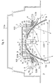
- the lamp generally designated 1 comprises a base part 2, with which it on or in a holding system 3 is held, and the one by means of an adjusting device 4 Reflector 5, which is adjustable by the adjusting device 4 and in each set position can be determined.
- Reflector 5 which is adjustable by the adjusting device 4 and in each set position can be determined.
- a lamp 6, here a halogen lamp held releasably by means of a socket 7, which is parallel to Central axis 8 of the symmetrical reflector 5 and the lamp 6 immovably on one Cross member 9 is held, on the base part 2 or here on the adjusting device 4th is attached.
- the lamp 1 is used in the present embodiment for lighting relatively small areas or spaces, e.g. for lighting Exhibition objects in exhibition rooms or museums.
- the lamp 1 by another Adjustment device 11 can be adjusted transversely to the central axis 8, in particular by pivoting and held lockable in the respective adjustment position.
- the adjustment movement can only in one direction, in two directions perpendicular to each other or in all Directions of the existing, here horizontal transverse plane E1 be directed. It can the suspension may be swinging or gimbal.
- the lamp 1 is on Spotlights e.g.
- the joint part 14b fastened to the holder is shown, which with respect to the first joint 12 in the longitudinal direction of the installation housing duct 15a preferably offset off-center, is attached here to the top of the holding plate 13a.
- the second joint part, not shown, can be directly or indirectly on the carrier 15 be attached.
- the lamp 1 is in a round hole 16 the holding plate 13a is pivotally mounted, the holding plate 13a being approximately in half Height of the lamp 1 is.
- the base part 2 is formed by a base ring 2a, which is located approximately at the level of the holding plate 13a with play in the hole 16.
- the first Joint 12 is formed by two pivot pins 12b projecting diametrically from base part 2 formed, each encompassing a bearing eye 12c formed on the holder 13, which by a trough and a plate 12d overlapping the pivot pin 12b, optionally with an upper trough can be formed.
- the plate 12d can with such great tension against the Press hinge pin 12b, e.g. be screwed that the lamp 1 by manual Overpressure is pivotable, but is found against an unwanted adjustment is.
- the light source 6a of the lamp 6 is located at the level of the hinge axis 12a.
- the reflector 5 can be one with opposite ones Walls in the form of profiles which are mirror images of the central plane E2, act in particular for elongated lights, as it e.g. is common with fluorescent tubes. In principle, such a reflector 5 can also be seen in FIG. 1.
- the lamp 1 and the reflector 5 in horizontal cross-section shaped round, the radiator preferably being is a cross reflector, in which a substantial part of each other opposite reflection surfaces or here from the round reflection surface 5a reflected rays S intersect the central axis 8.
- Adjustment device 4 designed so that the between the reflection surface 5a and Center axis 8 included angle W is variable.
- This will cause the Reflector wall 5b around a tilt axis 17, which is in the form of a profile with reflection surfaces extends in a transverse plane and lies approximately in the reflection surface 5a.
- this tilt axis 17 is essentially a tangent.
- the tilting axis 17 does not have to be stationary. You can too sideways or following the shape of the reflector wall 5b during the tilting process adjust.
- when tilting there is a vertical movement of the reflector 5 takes place, in particular in its upper end region.
- the adjusting device 4 has an effective parallel to the central axis 8 Movement drive 18 for the reflector 5 with an actuator 21, which of the Beam side 19 light 1 is accessible here.
- the actuator 21 acts through Movement change gear 22 on a slide 23 which is in a parallel to the Center axis 8 extending guide 24 slidably and with the upper region of the Reflector 5 is connected.
- the actuator 21 is a rotating ring 21a, which is free on the inner circumference of the base ring 2a is rotatably supported, engaging under the base ring 2a with a flange 21b and with engages in a spring or snap ring 25 seated in an annular groove, whereby a Pivot bearing is formed.
- the rotating ring 21a points from the flange 21b projecting engagement pins 21c.
- the inner circumference of the rotating ring 21a is rounded or shaped like a roof and sized so that the reflector 5 with its outside abuts a line of contact forming the tilt axis 17.
- a sleeve section 21d is formed, which forms the hollow cylindrical guide 24 inside, in the slider 23 is displaceable in the form of a disk 23a and a guide sleeve 23b is stored.
- the sleeve portion 21d and the cross member 9, here in the form of a Plate extend several arranged evenly distributed on the circumference Spacers 26, which by fastening screws 26a and surrounding sleeves 26b for the cross member 9 can be formed.
- this consists of overlapping scales Segments 5c, which are attached to a support part 32 only at their ends facing the lamp 6 attached, e.g. are riveted, s. Rivet 33 in Fig. 3.
- the support member 32 spans the segments 5c with its free ends radially outwards against the tilt axis 17 and it is preferably formed by a spring washer 32a to which the segments 5c are attached, and prestresses the segments 5c in the sense described above.
- the spring washer 32a can be concave or dome-shaped and form the reflector in the head area or from a concave or dome-shaped head reflector 5d.
- the support part 32 and the head reflector 5d are attached to the edge of a hole 34, e.g. handled, through which the lamp 6 extends into the upper region of the reflector 5.
- the reflector 5 can be moved by a manual movement of the Adjust actuator 21 axially and overall (straight profiled reflector for elongated lights) or in its lateral outer, formed by the segments 5c Tilt area. Positions can be selected in the existing adjustment range set in the two positions shown in FIG. 1 Adjustment range.
- the head region is in the position shown on the left in FIG. 1 of the reflector 5 in a rear, here upper with respect to the spreading device A. Position and the free edge of the reflector 5 in a laterally offset inwards Position. In the position shown on the right in FIG. 1, the head area of the Reflector 5 in a front, in this case lower position with respect to the direction of propagation A.
- the reflector 5 forms on both sides of the central plane E2 consequently the head area, which is movable or adjustable parallel to the central axis 8 and the side area around its attachment point in the head area in one at right angles to the center plane E2 swivel plane swivels with the Head area is connected and at the same time around this attachment point and around the associated tilt axis 17 pivots.
- the spreading of the side areas of the reflector 5 the dimension x takes place automatically due to the tension of the spring washer 32a, which Side areas biased outwards. This tension also ensures that the slide 23 is biased with the pins 28 against the curve sections 31 and thus by the Curve sections 31 does not stand out during an adjustment in the direction of propagation A.
- the above-described adjustment movements of the head area apply and the side areas of the reflector 5 both when the reflector is a 4 is also a profile-like body extending at right angles to the plane of the drawing when the reflector 5 has a round shape with respect to the plane E1.
- the first there is no need to divide the side areas of the reflector 5 into slats, since the Side areas can be adjusted as uniform wall parts.
- the reflector 5 With a round shape the reflector 5, on the other hand, requires the division of the side areas into one another overlapping segments 5c so that during the adjustment of the reflector 5 expansion and contraction of the round reflector peripheral wall taking place no gaps arise. Due to the spread caused by the spring washer 32a Segments ensure their tight contact with each other, so that there are no gaps here either arise.
- Reflector systems head reflector 5d and side areas or round peripheral wall with Segments 5c
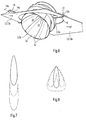
- FIGS. 7 and 8 7 a narrow beam setting and the corresponds to large cross-sectional dimension y
- the light distribution curve according to FIG. 8 corresponds to a wide beam setting and the smaller cross-sectional dimension x.
- Those shown in Figures 7 and 8 with solid lines Light distribution areas clarify the respective one caused by the head reflector 5d Light distribution.
- the light distribution partial areas shown in dashed lines illustrate the caused by the peripheral wall with the slats 5c of the reflector Light distribution areas.
- the dash-dotted light distribution areas clarify each a combined, through the head reflector 5d and the peripheral wall with the Segments 5c caused light distribution area.
Landscapes
- Engineering & Computer Science (AREA)
- General Engineering & Computer Science (AREA)
- Securing Globes, Refractors, Reflectors Or The Like (AREA)
- Non-Portable Lighting Devices Or Systems Thereof (AREA)
- Aerials With Secondary Devices (AREA)
- Optical Elements Other Than Lenses (AREA)
- Fastening Of Light Sources Or Lamp Holders (AREA)
Applications Claiming Priority (2)
| Application Number | Priority Date | Filing Date | Title |
|---|---|---|---|
| DE19714662 | 1997-04-09 | ||
| DE19714662A DE19714662A1 (de) | 1997-04-09 | 1997-04-09 | Leuchte mit einem verstellbaren Reflektor |
Publications (3)
| Publication Number | Publication Date |
|---|---|
| EP0870979A2 true EP0870979A2 (fr) | 1998-10-14 |
| EP0870979A3 EP0870979A3 (fr) | 2000-01-05 |
| EP0870979B1 EP0870979B1 (fr) | 2004-10-27 |
Family
ID=7825919
Family Applications (1)
| Application Number | Title | Priority Date | Filing Date |
|---|---|---|---|
| EP98106625A Expired - Lifetime EP0870979B1 (fr) | 1997-04-09 | 1998-04-09 | Luminaire avec un réflecteur ajustable |
Country Status (3)
| Country | Link |
|---|---|
| EP (1) | EP0870979B1 (fr) |
| AT (1) | ATE280925T1 (fr) |
| DE (2) | DE19714662A1 (fr) |
Cited By (6)
| Publication number | Priority date | Publication date | Assignee | Title |
|---|---|---|---|---|
| DE10103781A1 (de) * | 2001-01-29 | 2002-08-22 | Zimmermann Gmbh Co Kg Rudolf | Einrichtung zur Beleuchtung von Rettungswegen |
| EP1477728A2 (fr) | 2003-05-16 | 2004-11-17 | Reggiani S.p.A. Illuminazione | Dispositif d'éclairage encastré orientable |
| EP1626226A3 (fr) * | 2004-07-15 | 2006-09-13 | Ansorg GmbH | Luminaire comprenant un réflecteur dont la forme admet une symétrie de révolution |
| US7771086B2 (en) | 2004-07-27 | 2010-08-10 | Koninklijke Philips Electronics N.V. | Lighting device comprising a lamp unit a reflector |
| EP2325549A1 (fr) * | 2009-11-24 | 2011-05-25 | Alux Luxar GmbH & Co.KG | Réflecteur rond pour des rayonnements électromagnétiques |
| CN118856286A (zh) * | 2024-08-14 | 2024-10-29 | 湖北炬创环境艺术工程有限公司 | 一种夜间道路抢修用移动照明灯 |
Families Citing this family (2)
| Publication number | Priority date | Publication date | Assignee | Title |
|---|---|---|---|---|
| DE102014205663B4 (de) * | 2014-03-26 | 2016-03-17 | H4X E.U. | Halteanordnung für ein Funktionsbauteil einer Beleuchtungsvorrichtung, sowie Beleuchtungsvorrichtung |
| DE202016104062U1 (de) * | 2016-07-26 | 2017-10-27 | Zumtobel Lighting Gmbh | Anordnung zur Lichtabgabe |
Citations (1)
| Publication number | Priority date | Publication date | Assignee | Title |
|---|---|---|---|---|
| DE4304587A1 (de) | 1992-03-30 | 1993-10-07 | Zumtobel Licht | Reflektorverstellung für eine Leuchte mit rotationssymmetrischem Reflektor |
Family Cites Families (8)
| Publication number | Priority date | Publication date | Assignee | Title |
|---|---|---|---|---|
| GB600442A (en) * | 1945-12-21 | 1948-04-08 | Norman Ebenezer Hewitt | Projection lamps |
| DE30108C (de) * | A. BARA und E. DESJARDINS-LlEUX in Paris | Aufhängevorrichtung für Lampenschirme | ||
| FR757938A (fr) * | 1932-10-05 | 1934-01-08 | Réflecteur de lumière principalement pour l'éclairage de vitrines | |
| GB517777A (en) * | 1938-08-02 | 1940-02-08 | Alexander Twigg Patterson | Improvements in and relating to lamp shades |
| US3839632A (en) * | 1973-03-05 | 1974-10-01 | R Federico | Combination spotlight and floodlight |
| DE2523643C3 (de) * | 1975-05-28 | 1978-09-21 | Hans-Joachim 4010 Hilden Schurig | Reflektor mit einstellbarem Abstrahlwinkel |
| US4855884A (en) * | 1987-12-02 | 1989-08-08 | Morpheus Lights, Inc. | Variable beamwidth stage light |
| DE9204201U1 (de) * | 1992-03-30 | 1993-03-25 | Zumtobel Licht Ges.M.B.H., Dornbirn | Reflektorverstellung für eine Leuchte mit rotationssymmetrischem Reflektor |
-
1997
- 1997-04-09 DE DE19714662A patent/DE19714662A1/de not_active Ceased
-
1998
- 1998-04-09 EP EP98106625A patent/EP0870979B1/fr not_active Expired - Lifetime
- 1998-04-09 DE DE59812157T patent/DE59812157D1/de not_active Expired - Lifetime
- 1998-04-09 AT AT98106625T patent/ATE280925T1/de not_active IP Right Cessation
Patent Citations (1)
| Publication number | Priority date | Publication date | Assignee | Title |
|---|---|---|---|---|
| DE4304587A1 (de) | 1992-03-30 | 1993-10-07 | Zumtobel Licht | Reflektorverstellung für eine Leuchte mit rotationssymmetrischem Reflektor |
Cited By (7)
| Publication number | Priority date | Publication date | Assignee | Title |
|---|---|---|---|---|
| DE10103781A1 (de) * | 2001-01-29 | 2002-08-22 | Zimmermann Gmbh Co Kg Rudolf | Einrichtung zur Beleuchtung von Rettungswegen |
| EP1477728A2 (fr) | 2003-05-16 | 2004-11-17 | Reggiani S.p.A. Illuminazione | Dispositif d'éclairage encastré orientable |
| EP1477728A3 (fr) * | 2003-05-16 | 2007-07-11 | Reggiani S.p.A. Illuminazione | Dispositif d'éclairage encastré orientable |
| EP1626226A3 (fr) * | 2004-07-15 | 2006-09-13 | Ansorg GmbH | Luminaire comprenant un réflecteur dont la forme admet une symétrie de révolution |
| US7771086B2 (en) | 2004-07-27 | 2010-08-10 | Koninklijke Philips Electronics N.V. | Lighting device comprising a lamp unit a reflector |
| EP2325549A1 (fr) * | 2009-11-24 | 2011-05-25 | Alux Luxar GmbH & Co.KG | Réflecteur rond pour des rayonnements électromagnétiques |
| CN118856286A (zh) * | 2024-08-14 | 2024-10-29 | 湖北炬创环境艺术工程有限公司 | 一种夜间道路抢修用移动照明灯 |
Also Published As
| Publication number | Publication date |
|---|---|
| EP0870979A3 (fr) | 2000-01-05 |
| EP0870979B1 (fr) | 2004-10-27 |
| ATE280925T1 (de) | 2004-11-15 |
| DE59812157D1 (de) | 2004-12-02 |
| DE19714662A1 (de) | 1998-10-15 |
Similar Documents
| Publication | Publication Date | Title |
|---|---|---|
| DE2417605C3 (de) | Breitstrahlende Straßenleuchte | |
| DE7911733U1 (de) | Fahrzeugscheinwerfer-lampe und lageranordnung | |
| DE3844892C2 (de) | Reflektoranordnung und Abschirmung für eine Leuchte für Kompakt-Leuchtstofflampen | |
| EP0959296A2 (fr) | Luminaire avec un réflecteur ajustable | |
| DE2305666A1 (de) | Operationsleuchte mit einzelscheinwerfern | |
| EP0870979B1 (fr) | Luminaire avec un réflecteur ajustable | |
| DE69215882T2 (de) | Leuchten | |
| DE69227687T2 (de) | Medizinischer apparat zur beleuchtung eines behandlungsbereiches | |
| EP0802368A2 (fr) | Luminaire avec une lampe notamment a faible volume | |
| DE3316000A1 (de) | Leuchte fuer eine langgestreckte lichtquelle | |
| EP0768492A1 (fr) | Appareil d'éclairage indirect à faisceau large | |
| DE69305114T2 (de) | Kfz-Scheinwerfer mit einstellbarem Reflektor | |
| EP1626226B1 (fr) | Luminaire comprenant un réflecteur dont la forme admet une symétrie de révolution | |
| EP0194590B1 (fr) | Armature lumineuse allongée avec réflecteur incorporé | |
| DE10252724A1 (de) | Verlichtingstoestel | |
| DE2812090A1 (de) | Leuchte fuer reflektorlampen | |
| DE69415761T2 (de) | Leuchte mit verstellbarer Optik | |
| DE29915780U1 (de) | Schwenkbare Leuchtenhalterung | |
| DE19821721C2 (de) | Standleuchte für Innenräume | |
| DE29503526U1 (de) | Leuchtenträger, insbesondere für Einbauleuchten | |
| DE1497316A1 (de) | Beleuchtungskoerper mit Rueckstrahlvorrichtung | |
| DE202022106491U1 (de) | Leuchte mit veränderbarer Abstrahlcharakteristik, Beleuchtungssystem und Verwendung | |
| AT379007B (de) | Raumleuchte mit einem leuchtengehaeuse und einer lampe | |
| DE2513821C2 (de) | Breitstrahlende Straßenleuchte mit einer Reflektoranordnung, die ein um eine horizontale Achse drehbares Schwenkelement enthält | |
| DE69719916T2 (de) | Leuchtstofflampen-Beleuchtungseinrichtung mit drehbaren Reflektoren |
Legal Events
| Date | Code | Title | Description |
|---|---|---|---|
| PUAI | Public reference made under article 153(3) epc to a published international application that has entered the european phase |
Free format text: ORIGINAL CODE: 0009012 |
|
| AK | Designated contracting states |
Kind code of ref document: A2 Designated state(s): AT CH DE LI |
|
| AX | Request for extension of the european patent |
Free format text: AL;LT;LV;MK;RO;SI |
|
| PUAL | Search report despatched |
Free format text: ORIGINAL CODE: 0009013 |
|
| AK | Designated contracting states |
Kind code of ref document: A3 Designated state(s): AT BE CH CY DE DK ES FI FR GB GR IE IT LI LU MC NL PT SE |
|
| AX | Request for extension of the european patent |
Free format text: AL;LT;LV;MK;RO;SI |
|
| 17P | Request for examination filed |
Effective date: 20000705 |
|
| AKX | Designation fees paid |
Free format text: AT CH DE LI |
|
| 17Q | First examination report despatched |
Effective date: 20020419 |
|
| GRAP | Despatch of communication of intention to grant a patent |
Free format text: ORIGINAL CODE: EPIDOSNIGR1 |
|
| GRAS | Grant fee paid |
Free format text: ORIGINAL CODE: EPIDOSNIGR3 |
|
| GRAA | (expected) grant |
Free format text: ORIGINAL CODE: 0009210 |
|
| AK | Designated contracting states |
Kind code of ref document: B1 Designated state(s): AT CH DE LI |
|
| REG | Reference to a national code |
Ref country code: CH Ref legal event code: EP |
|
| REG | Reference to a national code |
Ref country code: CH Ref legal event code: NV Representative=s name: A. BRAUN, BRAUN, HERITIER, ESCHMANN AG PATENTANWAE |
|
| REF | Corresponds to: |
Ref document number: 59812157 Country of ref document: DE Date of ref document: 20041202 Kind code of ref document: P |
|
| PLBE | No opposition filed within time limit |
Free format text: ORIGINAL CODE: 0009261 |
|
| STAA | Information on the status of an ep patent application or granted ep patent |
Free format text: STATUS: NO OPPOSITION FILED WITHIN TIME LIMIT |
|
| 26N | No opposition filed |
Effective date: 20050728 |
|
| REG | Reference to a national code |
Ref country code: CH Ref legal event code: PFA Owner name: ZUMTOBEL STAFF GMBH Free format text: ZUMTOBEL STAFF GMBH#SCHWEIZER STRASSE 30#6850 DORNBIRN (AT) -TRANSFER TO- ZUMTOBEL STAFF GMBH#SCHWEIZER STRASSE 30#6850 DORNBIRN (AT) |
|
| PGFP | Annual fee paid to national office [announced via postgrant information from national office to epo] |
Ref country code: AT Payment date: 20100422 Year of fee payment: 13 |
|
| PGFP | Annual fee paid to national office [announced via postgrant information from national office to epo] |
Ref country code: CH Payment date: 20100426 Year of fee payment: 13 |
|
| REG | Reference to a national code |
Ref country code: CH Ref legal event code: PL |
|
| REG | Reference to a national code |
Ref country code: AT Ref legal event code: MM01 Ref document number: 280925 Country of ref document: AT Kind code of ref document: T Effective date: 20110409 |
|
| PG25 | Lapsed in a contracting state [announced via postgrant information from national office to epo] |
Ref country code: CH Free format text: LAPSE BECAUSE OF NON-PAYMENT OF DUE FEES Effective date: 20110430 Ref country code: LI Free format text: LAPSE BECAUSE OF NON-PAYMENT OF DUE FEES Effective date: 20110430 |
|
| PG25 | Lapsed in a contracting state [announced via postgrant information from national office to epo] |
Ref country code: AT Free format text: LAPSE BECAUSE OF NON-PAYMENT OF DUE FEES Effective date: 20110409 |
|
| PGFP | Annual fee paid to national office [announced via postgrant information from national office to epo] |
Ref country code: DE Payment date: 20120702 Year of fee payment: 15 |
|
| PG25 | Lapsed in a contracting state [announced via postgrant information from national office to epo] |
Ref country code: DE Free format text: LAPSE BECAUSE OF NON-PAYMENT OF DUE FEES Effective date: 20131101 |
|
| REG | Reference to a national code |
Ref country code: DE Ref legal event code: R119 Ref document number: 59812157 Country of ref document: DE Effective date: 20131101 |