EP0872014B1 - Fahrzeugbordnetz - Google Patents
Fahrzeugbordnetz Download PDFInfo
- Publication number
- EP0872014B1 EP0872014B1 EP96943901A EP96943901A EP0872014B1 EP 0872014 B1 EP0872014 B1 EP 0872014B1 EP 96943901 A EP96943901 A EP 96943901A EP 96943901 A EP96943901 A EP 96943901A EP 0872014 B1 EP0872014 B1 EP 0872014B1
- Authority
- EP
- European Patent Office
- Prior art keywords
- voltage
- electrical system
- vehicle
- board electrical
- generator
- Prior art date
- Legal status (The legal status is an assumption and is not a legal conclusion. Google has not performed a legal analysis and makes no representation as to the accuracy of the status listed.)
- Expired - Lifetime
Links
Images

Classifications
-
- H—ELECTRICITY
- H02—GENERATION; CONVERSION OR DISTRIBUTION OF ELECTRIC POWER
- H02J—ELECTRIC POWER NETWORKS; CIRCUIT ARRANGEMENTS OR SYSTEMS FOR SUPPLYING OR DISTRIBUTING ELECTRIC POWER; SYSTEMS FOR STORING ELECTRIC ENERGY
- H02J7/00—Circuit arrangements for charging or discharging batteries or for supplying loads from batteries
- H02J7/14—Circuit arrangements for charging or discharging batteries or for supplying loads from batteries for charging batteries from dynamo-electric generators driven at varying speed, e.g. on vehicle
- H02J7/1438—Circuit arrangements for charging or discharging batteries or for supplying loads from batteries for charging batteries from dynamo-electric generators driven at varying speed, e.g. on vehicle in combination with power supplies for loads other than batteries
-
- H—ELECTRICITY
- H02—GENERATION; CONVERSION OR DISTRIBUTION OF ELECTRIC POWER
- H02M—APPARATUS FOR CONVERSION BETWEEN AC AND AC, BETWEEN AC AND DC, OR BETWEEN DC AND DC, AND FOR USE WITH MAINS OR SIMILAR POWER SUPPLY SYSTEMS; CONVERSION OF DC OR AC INPUT POWER INTO SURGE OUTPUT POWER; CONTROL OR REGULATION THEREOF
- H02M3/00—Conversion of DC power input into DC power output
- H02M3/02—Conversion of DC power input into DC power output without intermediate conversion into AC
- H02M3/04—Conversion of DC power input into DC power output without intermediate conversion into AC by static converters
- H02M3/10—Conversion of DC power input into DC power output without intermediate conversion into AC by static converters using discharge tubes with control electrode or semiconductor devices with control electrode
- H02M3/145—Conversion of DC power input into DC power output without intermediate conversion into AC by static converters using discharge tubes with control electrode or semiconductor devices with control electrode using devices of a triode or transistor type requiring continuous application of a control signal
- H02M3/155—Conversion of DC power input into DC power output without intermediate conversion into AC by static converters using discharge tubes with control electrode or semiconductor devices with control electrode using devices of a triode or transistor type requiring continuous application of a control signal using semiconductor devices only
- H02M3/156—Conversion of DC power input into DC power output without intermediate conversion into AC by static converters using discharge tubes with control electrode or semiconductor devices with control electrode using devices of a triode or transistor type requiring continuous application of a control signal using semiconductor devices only with automatic control of output voltage or current, e.g. switching regulators
- H02M3/158—Conversion of DC power input into DC power output without intermediate conversion into AC by static converters using discharge tubes with control electrode or semiconductor devices with control electrode using devices of a triode or transistor type requiring continuous application of a control signal using semiconductor devices only with automatic control of output voltage or current, e.g. switching regulators including plural semiconductor devices as final control devices for a single load
-
- H—ELECTRICITY
- H02—GENERATION; CONVERSION OR DISTRIBUTION OF ELECTRIC POWER
- H02P—CONTROL OR REGULATION OF ELECTRIC MOTORS, ELECTRIC GENERATORS OR DYNAMO-ELECTRIC CONVERTERS; CONTROLLING TRANSFORMERS, REACTORS OR CHOKE COILS
- H02P9/00—Arrangements for controlling electric generators for the purpose of obtaining a desired output
- H02P9/14—Arrangements for controlling electric generators for the purpose of obtaining a desired output by variation of field
- H02P9/26—Arrangements for controlling electric generators for the purpose of obtaining a desired output by variation of field using discharge tubes or semiconductor devices
- H02P9/30—Arrangements for controlling electric generators for the purpose of obtaining a desired output by variation of field using discharge tubes or semiconductor devices using semiconductor devices
- H02P9/305—Arrangements for controlling electric generators for the purpose of obtaining a desired output by variation of field using discharge tubes or semiconductor devices using semiconductor devices controlling voltage
- H02P9/307—Arrangements for controlling electric generators for the purpose of obtaining a desired output by variation of field using discharge tubes or semiconductor devices using semiconductor devices controlling voltage more than one voltage output
-
- B—PERFORMING OPERATIONS; TRANSPORTING
- B60—VEHICLES IN GENERAL
- B60R—VEHICLES, VEHICLE FITTINGS, OR VEHICLE PARTS, NOT OTHERWISE PROVIDED FOR
- B60R16/00—Electric or fluid circuits specially adapted for vehicles and not otherwise provided for; Arrangement of elements of electric or fluid circuits specially adapted for vehicles and not otherwise provided for
- B60R16/02—Electric or fluid circuits specially adapted for vehicles and not otherwise provided for; Arrangement of elements of electric or fluid circuits specially adapted for vehicles and not otherwise provided for electric constitutive elements
- B60R16/03—Electric or fluid circuits specially adapted for vehicles and not otherwise provided for; Arrangement of elements of electric or fluid circuits specially adapted for vehicles and not otherwise provided for electric constitutive elements for supply of electrical power to vehicle subsystems or for
-
- F—MECHANICAL ENGINEERING; LIGHTING; HEATING; WEAPONS; BLASTING
- F02—COMBUSTION ENGINES; HOT-GAS OR COMBUSTION-PRODUCT ENGINE PLANTS
- F02D—CONTROLLING COMBUSTION ENGINES
- F02D41/00—Electrical control of supply of combustible mixture or its constituents
- F02D41/20—Output circuits, e.g. for controlling currents in command coils
- F02D2041/2003—Output circuits, e.g. for controlling currents in command coils using means for creating a boost voltage, i.e. generation or use of a voltage higher than the battery voltage, e.g. to speed up injector opening
- F02D2041/201—Output circuits, e.g. for controlling currents in command coils using means for creating a boost voltage, i.e. generation or use of a voltage higher than the battery voltage, e.g. to speed up injector opening by using a boost inductance
-
- F—MECHANICAL ENGINEERING; LIGHTING; HEATING; WEAPONS; BLASTING
- F02—COMBUSTION ENGINES; HOT-GAS OR COMBUSTION-PRODUCT ENGINE PLANTS
- F02D—CONTROLLING COMBUSTION ENGINES
- F02D41/00—Electrical control of supply of combustible mixture or its constituents
- F02D41/20—Output circuits, e.g. for controlling currents in command coils
- F02D2041/2003—Output circuits, e.g. for controlling currents in command coils using means for creating a boost voltage, i.e. generation or use of a voltage higher than the battery voltage, e.g. to speed up injector opening
- F02D2041/2013—Output circuits, e.g. for controlling currents in command coils using means for creating a boost voltage, i.e. generation or use of a voltage higher than the battery voltage, e.g. to speed up injector opening by using a boost voltage source
-
- F—MECHANICAL ENGINEERING; LIGHTING; HEATING; WEAPONS; BLASTING
- F02—COMBUSTION ENGINES; HOT-GAS OR COMBUSTION-PRODUCT ENGINE PLANTS
- F02D—CONTROLLING COMBUSTION ENGINES
- F02D2400/00—Control systems adapted for specific engine types; Special features of engine control systems not otherwise provided for; Power supply, connectors or cabling for engine control systems
- F02D2400/14—Power supply for engine control systems
-
- H—ELECTRICITY
- H02—GENERATION; CONVERSION OR DISTRIBUTION OF ELECTRIC POWER
- H02J—ELECTRIC POWER NETWORKS; CIRCUIT ARRANGEMENTS OR SYSTEMS FOR SUPPLYING OR DISTRIBUTING ELECTRIC POWER; SYSTEMS FOR STORING ELECTRIC ENERGY
- H02J2105/00—Networks for supplying or distributing electric power characterised by their spatial reach or by the load
- H02J2105/30—Networks for supplying or distributing electric power characterised by their spatial reach or by the load the load networks being external to vehicles, i.e. exchanging power with vehicles
- H02J2105/33—Networks for supplying or distributing electric power characterised by their spatial reach or by the load the load networks being external to vehicles, i.e. exchanging power with vehicles exchanging power with road vehicles
-
- H—ELECTRICITY
- H02—GENERATION; CONVERSION OR DISTRIBUTION OF ELECTRIC POWER
- H02P—CONTROL OR REGULATION OF ELECTRIC MOTORS, ELECTRIC GENERATORS OR DYNAMO-ELECTRIC CONVERTERS; CONTROLLING TRANSFORMERS, REACTORS OR CHOKE COILS
- H02P2101/00—Special adaptation of control arrangements for generators
- H02P2101/45—Special adaptation of control arrangements for generators for motor vehicles, e.g. car alternators
-
- Y—GENERAL TAGGING OF NEW TECHNOLOGICAL DEVELOPMENTS; GENERAL TAGGING OF CROSS-SECTIONAL TECHNOLOGIES SPANNING OVER SEVERAL SECTIONS OF THE IPC; TECHNICAL SUBJECTS COVERED BY FORMER USPC CROSS-REFERENCE ART COLLECTIONS [XRACs] AND DIGESTS
- Y02—TECHNOLOGIES OR APPLICATIONS FOR MITIGATION OR ADAPTATION AGAINST CLIMATE CHANGE
- Y02T—CLIMATE CHANGE MITIGATION TECHNOLOGIES RELATED TO TRANSPORTATION
- Y02T10/00—Road transport of goods or passengers
- Y02T10/60—Other road transportation technologies with climate change mitigation effect
- Y02T10/70—Energy storage systems for electromobility, e.g. batteries
Definitions
- the invention relates to a vehicle electrical system.
- the three-phase voltage generated in the generator is from a diode rectifier into the required on-board electrical system DC voltage.
- rectifier circuits are known in which rectifier, Schottky or Zener diodes are used. Combinations are also different Diode designs possible in a rectifier. Parallel connections of diodes for Increases in the maximum current are also used if necessary.
- the amplitude of the rectifier output voltage is determined by a voltage regulator the generator excitation circuit is connected to the power supply for the On-board electrical system required value regulated.
- the low one Vehicle electrical system voltage due to the resulting high currents problematic.
- the resulting high losses be taken into account when designing the cable cross-sections.
- semiconductor components in high-performance consumers Use they are also to be dimensioned for the high currents, which leads to an increase in costs.
- the invention is based on the problem, in addition to the conventional one On-board electrical system voltage U1 of nominal 12 V is another, higher DC voltage level U2 constant voltage for powerful electrical To provide consumers.
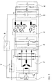
- a multiple chopper consists of connecting several chopper stages (step-up / step-down converters) in parallel, as is shown, for example, in FIG. 1.
- the problems with EMC known from choppers of this type are the pulse-shaped input current and the pulse-shaped output voltage when operating without an additional choke. If one omits a continuous variation of the output voltage U1 and is limited to a certain number of discretely adjustable output voltage levels, the combined use of several choppers can considerably improve the EMC of the circuit by smoothing the currents le and la and avoiding a pulsed output voltage U1 .
- chopper stages (1, 2, .. k) are connected in parallel as shown in FIG. 1, so that the load current can be divided into the controlled branch currents I1, I2, .. Ik depending on the control pattern Ust1, Ust2, .. Ustk.
- the individual stages are decoupled from one another by the built-in chokes L1, L2, .. Lk and by the separate freewheeling circuits via the freewheeling diodes D1, D2, .. Dk and do not influence one another.
- the number of active stages in operation can differ from the total number of chopper stages depending on the desired voltage ratio. This means that not all branches have to be constantly involved in the current supply.
- the electronic switches S1, S2, .. Sk are now controlled in such a way that the Number of controlled branches remains constant over a cycle period. However, depending on the number of stages k, this condition can only apply to certain ones discrete tactile and thus tension ratios (fractions or multiples of Input voltage Ue) are met. It follows that the number of Chopper stages connected in parallel must be selected the larger the finer the desired voltage level.
- n total number of existing stages
- m number of active stages in operation
- n number of simultaneously activated stages. The following applies: n ⁇ m ⁇ k
- Fig. 2 shows the drive pulse sequence for an arrangement with four electronic switches and the set voltage ratios 1/4 and 3/4. The number of the same for each time period is clearly recognizable controlled levels.
- the second, higher voltage level U2 now takes place in accordance with that in FIG. 3 shown arrangement.
- the following components are used in it: a conventional generator regulator 1 for regulating the battery voltage 12V, a generator with rectifier 2, a multiple chopper 4 and one Charge control 7.
- the generator G is energized when the ignition lock 8 is switched on.
- the 12V generator regulator (IC) is connected to the excitation winding of the generator connected. It has the task of varying the control variable in the control loop effective excitation current, the battery voltage U1 to the desired value to regulate from nominal 12V. It can be a conventional IC voltage regulator be used for automotive generators.
- the energy supply of the excitation circuit and the measurement of the voltage to be regulated is not carried out via the usual method Excitation diodes from the generator but from the switched battery voltage at terminal 15. This regulates the battery voltage directly as desired.
- the voltage delivered by the generator G to the load 3 is of course that Voltage U2 of the higher voltage level.
- the generator G with excitation and three-phase stator winding generates a three-phase voltage system, the amplitude of which can be adjusted via the excitation current. Rectification takes place with the help of one or more diode bridges.
- the 12V loads 6 can be connected to the output of the multiple chopper 4, which acts as a buck converter. Any necessary relay excitation coils can be supplied from terminal 30, from terminal 15 or directly from a diode bridge integrated in the generator.
- a major advantage of the arrangement is that the voltage ripple in the battery-backed system can be reduced.
- the higher direct voltage system U2 generated directly by the generator with its voltage amplitude dependent on the multiple chopper 4 used can be used to connect powerful consumers 3.
- the Supply of any necessary relay excitation coils can also be done here from terminal 30, from terminal 15, from the voltage system U2 or directly from a diode bridge integrated in the generator.
Landscapes
- Engineering & Computer Science (AREA)
- Power Engineering (AREA)
- Control Of Eletrric Generators (AREA)
- Synchronous Machinery (AREA)
Description
Verzichtet man auf eine kontinuierliche Variation der Ausgangsspannung U1 und beschränkt sich auf eine bestimmte Anzahl diskret einstellbarer Ausgangsspannungsniveaus, so läßt sich durch den kombinierten Einsatz mehrerer Chopper die EMV der Schaltung durch die Glättung der Ströme le und la und die Vermeidung einer pulsförmigen Ausgangsspannung U1 erheblich verbessern.
Die Anzahl der in Betrieb befindlichen, aktiven Stufen kann je nach gewünschtem Spannungsverhältnis von der Gesamtzahl der Chopperstufen abweichen. Dies bedeutet, daß nicht ständig alle Zweige an der Stromführung beteiligt sein müssen.
| Kombinationsmatrix | |||||||
| m | 1 | 2 | 3 | 4 | .. | k | |
| n | |||||||
| 1 | 1 | 1/2 | 1/3 | 1/4 | .. | 1/k | |
| 2 | 1 | 2/3 | 2/4 | .. | 2/k | ||
| 3 | 1 | 3/4 | .. | 3/k | |||
| 4 | 1 | .. | 4/k | ||||
| .. | .. | ||||||
| k | 1 |
k: Gesamtzahl der vorhandenen Stufen, m: Anzahl der in Betrieb befindlichen, aktiven Stufen, n: Zahl der gleichzeitig angesteuerten Stufen.
Es gilt: n < m < k
- die Regelung der Batteriespannung U1 erfolgt direkt durch Messung der Spannung an Klemme 15
- die Amplitude der zweiten, höheren Spannungsebene U2 kann in Abhängigkeit von Ausführung und Ansteuerung des Mehrfach-Choppers in Stufen eingestellt werden
- eine Leistungsstellung ohne Beeinflußung des batteriegepufferten Spannungssystems ist möglich
- die Spannungswelligkeit im batteriegepufferten Spannungssystem kann reduziert werden und
- die Versorgung von Lasten an U2 aus U1 ist auch bei stillstehendem Generator möglich.
- es kann eine Reduzierung des Maximalstromes erreicht werden
- bei gleicher Verbraucherleistung reduzieren sich die ohmschen Verluste
- es können Leitungen mit geringerem Querschnitt verlegt werden, was einen Gewichtsvorteil erbringt
- die Halbleiterbauelemente werden hinsichtlich der Spannungsfestigkeit besser ausgenutzt
- bei gleicher Verbraucherleistung reduzieren sich die Halbleiterkosten, da sich die benötigte Chipfläche verkleinert
- bei gleicher Verbraucherleistung reduzieren sich die Halbleiterverluste
- reduzierte Halbleiterverluste bedeuten einen geringeren Kühlaufwand, der wiederum einen Gewichtsvorteil erbringt
- der Wirkungsgrad der Endstufen erhöht sich und
- bei gleicher Chipfläche kann die maximale Umrichterleistung erhöht werden.
Claims (8)
- Fahrzeugbordnetz mit einem Generator, dessen Erregerkreis von einem Spannungsregler beeinflußt wird, wobei neben einer ersten Spannungsebene (U1) von 12 Volt eine zweite, höhere Spannungsebene (U2) vorgesehen ist, wobei die zweite Spannungsebene (U2) am Ausgang des Generators ansteht und die erste, niedrigere Spannungsebene (U1) durch eine Parallelschaltung mehrerer Chopperstufen realisiert ist und wobei der Spannungsregler die erste niedrige Spannungsebene (U1) regelt.
- Fahrzeugbordnetz nach Anspruch 1,
dadurch gekennzeichnet,
daß die Spannungsregelung (U2) der höheren Ebene die Spannung am Generator ist, die sich in ihrer Höhe durch ein einstellbares Übersetzungsverhältnis (a) aus der ersten Spannungsebene von 12V ergibt. - Fahrzeugbordnetz nach Anspruch 1 oder 2,
dadurch gekennzeichnet,
daß eine Schaltungsanordnung zur Spannungsumsetzung mit einem Schalter (S), einer Induktivität (Drossel L) und einer Diode (D) vorgesehen ist, die zusammen eine T-förmige Anordnung bilden, wobei sich in jedem Schenkel jedes Element befinden kann und die Diode in der Richtung eingebaut ist, daß sie einen kontinuierlichen Stromfluß in der Induktivität und im Verbraucher hervorruft. - Fahrzeugbordnetz nach Anspruch 3,
dadurch gekennzeichnet,
daß die Dioden durch aktive Bauelemente ersetzt sind. - Fahrzeugbordnetz nach Anspruch 3 oder 4,
dadurch gekennzeichnet,
daß die Anzahl der parallel geschalteten Wandler umgekehrt proportional zur Höhe der kleinsten erzielbaren Spannungsstufe ist, und daß die Tastverhältnisse jeder einzelnen der parallelgeschalteten Wandlerstufen konstant und so gegeneinander phasenverschoben sind, daß die Summe der Spannungen und Ströme am Ausgang zu jedem Zeitpunkt konstant ist. - Fahrzeugbordnetz nach Anspruch 3,
dadurch gekennzeichnet,
daß die Schalter (S1...Sk) so getaktet sind, daß die Anzahl der gleichzeitig angesteuerten Schalter während einer von der gewählten Frequenz abhängigen Taktperiode konstant ist. - Fahrzeugbordnetz nach einem der Ansprüche 3 bis 6,
dadurch gekennzeichnet,
daß die Schaltungsanordnung als Hochsetzsteller verwendet wird. - Fahrzeugbordnetz nach einem der Ansprüche 3 bis 6,
dadurch gekennzeichnet,
daß die Schaltungsanordnung als Hoch-/ Tiefsetzsteller (Buck-Boost-Konverter) verwendet wird.
Applications Claiming Priority (3)
| Application Number | Priority Date | Filing Date | Title |
|---|---|---|---|
| DE19600074A DE19600074C2 (de) | 1996-01-03 | 1996-01-03 | Fahrzeugbordnetz |
| DE19600074 | 1996-01-03 | ||
| PCT/EP1996/005490 WO1997025771A1 (de) | 1996-01-03 | 1996-12-07 | Fahrzeugbordnetz |
Publications (2)
| Publication Number | Publication Date |
|---|---|
| EP0872014A1 EP0872014A1 (de) | 1998-10-21 |
| EP0872014B1 true EP0872014B1 (de) | 1999-10-27 |
Family
ID=7782094
Family Applications (1)
| Application Number | Title | Priority Date | Filing Date |
|---|---|---|---|
| EP96943901A Expired - Lifetime EP0872014B1 (de) | 1996-01-03 | 1996-12-07 | Fahrzeugbordnetz |
Country Status (5)
| Country | Link |
|---|---|
| US (1) | US6043567A (de) |
| EP (1) | EP0872014B1 (de) |
| JP (1) | JP3135581B2 (de) |
| DE (2) | DE19600074C2 (de) |
| WO (1) | WO1997025771A1 (de) |
Cited By (1)
| Publication number | Priority date | Publication date | Assignee | Title |
|---|---|---|---|---|
| DE102016011537A1 (de) | 2016-09-23 | 2018-03-29 | Audi Ag | Kraftfahrzeug |
Families Citing this family (18)
| Publication number | Priority date | Publication date | Assignee | Title |
|---|---|---|---|---|
| JPH09191693A (ja) * | 1996-01-05 | 1997-07-22 | Hitachi Ltd | 充電発電機及び電圧調整器 |
| DE19846319C1 (de) * | 1998-10-08 | 2000-02-17 | Daimler Chrysler Ag | Energieversorgungsschaltung für ein Kraftfahrzeugbordnetz mit zwei Spannungsversorgungszweigen |
| FR2790616B1 (fr) * | 1999-03-05 | 2001-07-27 | Sagem | Circuit changeur de tension a decoupages decales et reseau de distribution d'energie en faisant application |
| ES2164578B1 (es) * | 1999-12-24 | 2003-05-16 | Lear Automotive Eeds Spain | Convertidor en "interleaving" de energia electrica continua-continua. |
| DE10013459A1 (de) * | 2000-03-17 | 2001-09-27 | Compact Dynamics Gmbh | Schaltungsanordnung zum Betreiben von elektrischen oder elektronischen Komponenten in einem Kraftfahrzeug mit einem Zwei-Spannungs-Bordnetz |
| DE10022760A1 (de) * | 2000-05-10 | 2001-11-22 | Siemens Ag | Verfahren zur Ansteuerung einer Anordnung zur elektrischen Energiespeicherung sowie Anordnung zur elektrischen Energiespeicherung |
| DE10042526A1 (de) * | 2000-08-30 | 2001-08-02 | Audi Ag | Generator zur elektrischen Spannungsversorgung eines Kraftfahrzeuges |
| US6674180B2 (en) | 2001-10-12 | 2004-01-06 | Ford Global Technologies, Llc | Power supply for a hybrid electric vehicle |
| DE10162268A1 (de) * | 2001-12-18 | 2003-07-10 | Siemens Ag | Dimmbares Anzeigeelement |
| JP2004072980A (ja) * | 2002-08-09 | 2004-03-04 | Denso Corp | 車載用フライホイルバッテリ |
| US7251553B2 (en) * | 2003-04-30 | 2007-07-31 | Robert Bosch Corporation | Thermal optimization of EMI countermeasures |
| US7130180B2 (en) * | 2003-07-09 | 2006-10-31 | Champion Aerospace, Inc. | Partitioned exciter system |
| DE102007024567A1 (de) * | 2007-05-25 | 2008-11-27 | Daimler Ag | Hochvolt-Bordnetzarchitektur für ein Brennstoffzellen-Fahrzeug sowie integrierte Leistungselektronik für eine Hochvolt-Bordnetzarchitektur |
| DE102010063041A1 (de) * | 2010-12-14 | 2012-06-14 | Robert Bosch Gmbh | Generatorvorrichtung mit verbesserter Verpolfestigkeit |
| JP5680600B2 (ja) * | 2012-09-07 | 2015-03-04 | 株式会社日本製鋼所 | 電動射出成形機の直流電圧供給回路 |
| JP2016106510A (ja) * | 2015-11-24 | 2016-06-16 | 有限会社エーユー建築工房 | 充電装置 |
| DE102016002465B4 (de) | 2016-03-01 | 2020-11-05 | Audi Ag | Reglervorrichtung und Verfahren zum Einstellen eines Batteriestromes einer Batterie eines Kraftfahrzeugs |
| US12233747B2 (en) | 2021-12-17 | 2025-02-25 | Ford Global Technologies, Llc | Varying vehicle charging bus |
Family Cites Families (15)
| Publication number | Priority date | Publication date | Assignee | Title |
|---|---|---|---|---|
| DE2755246C2 (de) * | 1977-12-12 | 1982-06-03 | Siemens AG, 1000 Berlin und 8000 München | Schaltungsanordnung für die Bremsung einer Gleichstrom-Reihenschlußmaschine |
| FR2390849A1 (fr) * | 1977-05-12 | 1978-12-08 | Anvar | Commande de moteur electrique a courant continu, en particulier pour voiture electrique |
| US4143280A (en) * | 1977-07-01 | 1979-03-06 | General Electric Company | Control system for a tertiary winding self-excited generator |
| US4604528A (en) * | 1984-01-10 | 1986-08-05 | Peter Norton | Dual voltage power supply system for vehicles |
| US4992672A (en) * | 1988-06-09 | 1991-02-12 | Peter Norton | Dual or single voltage vehicular power supply with improved switch driver and load pump |
| JP2572408B2 (ja) * | 1988-01-18 | 1997-01-16 | 株式会社日立製作所 | 車両用電源装置 |
| JPH02184300A (ja) * | 1989-01-09 | 1990-07-18 | Mitsubishi Electric Corp | 車両用交流発電機の制御装置 |
| DE4041220A1 (de) * | 1990-12-21 | 1992-07-02 | Vogt Electronic Ag | Stromversorgung fuer kraftfahrzeuge |
| JP3039119B2 (ja) * | 1992-03-31 | 2000-05-08 | 日産自動車株式会社 | 車両用電源装置 |
| GB2279514A (en) * | 1993-06-24 | 1995-01-04 | Strand Lighting Ltd | Power control converter circuit |
| IT1260956B (it) * | 1993-08-04 | 1996-04-29 | Dispositivo regolatore di tensione, ad esempio per motocicli | |
| DE4419006A1 (de) * | 1994-05-31 | 1995-12-07 | Hella Kg Hueck & Co | Pulsweitenmodulierter Schaltwandler zum Betrieb elektrischer Verbraucher |
| US5642023A (en) * | 1995-01-19 | 1997-06-24 | Textron Inc. | Method and apparatus for the electronic control of electric motor driven golf car |
| JP3465454B2 (ja) * | 1995-04-24 | 2003-11-10 | 株式会社デンソー | 発電装置 |
| JP3412330B2 (ja) * | 1995-04-24 | 2003-06-03 | 株式会社デンソー | 車両用発電装置 |
-
1996
- 1996-01-03 DE DE19600074A patent/DE19600074C2/de not_active Expired - Fee Related
- 1996-12-07 JP JP09524785A patent/JP3135581B2/ja not_active Expired - Fee Related
- 1996-12-07 US US09/101,089 patent/US6043567A/en not_active Expired - Fee Related
- 1996-12-07 WO PCT/EP1996/005490 patent/WO1997025771A1/de not_active Ceased
- 1996-12-07 DE DE59603515T patent/DE59603515D1/de not_active Expired - Fee Related
- 1996-12-07 EP EP96943901A patent/EP0872014B1/de not_active Expired - Lifetime
Cited By (1)
| Publication number | Priority date | Publication date | Assignee | Title |
|---|---|---|---|---|
| DE102016011537A1 (de) | 2016-09-23 | 2018-03-29 | Audi Ag | Kraftfahrzeug |
Also Published As
| Publication number | Publication date |
|---|---|
| DE59603515D1 (de) | 1999-12-02 |
| JPH11507499A (ja) | 1999-06-29 |
| EP0872014A1 (de) | 1998-10-21 |
| US6043567A (en) | 2000-03-28 |
| JP3135581B2 (ja) | 2001-02-19 |
| DE19600074C2 (de) | 2002-07-18 |
| DE19600074A1 (de) | 1997-07-17 |
| WO1997025771A1 (de) | 1997-07-17 |
Similar Documents
| Publication | Publication Date | Title |
|---|---|---|
| EP0872014B1 (de) | Fahrzeugbordnetz | |
| DE3743317C2 (de) | ||
| EP2363947B1 (de) | Wechselrichter mit mehrfach versorgtem Bordnetz | |
| DE112009001695B4 (de) | Stromversorgungsvorrichtung | |
| DE102018106305B4 (de) | Wechselstromladung einer intelligenten Batterie | |
| EP1784910B1 (de) | Spannungsregler mit überspannungsschutz | |
| DE102009000096A1 (de) | Verfahren für die Steuerung einer Stromversorgungseinrichtung mit einem Wechselrichter | |
| DE102016200662A1 (de) | Bidirektionaler DC/DC-Wandler und Verfahren zum Laden des Zwischenkreiskondensators eines DC/DC-Wandlers aus der Niedervoltbatterie | |
| DE102013213802A1 (de) | Überspannungsschutz für aktive Gleichrichter bei Lastabwurf | |
| WO2013010693A1 (de) | System mit batterieladegerät und bordnetzversorgungsstufe | |
| DE102012202863A1 (de) | System und Verfahren zum Ansteuern einer Energiespeichereinrichtung | |
| DE19838296B4 (de) | Elektrisches Spannungsversorgungssystem | |
| DE102017010390A1 (de) | Energiewandler | |
| DE102012202867A1 (de) | Ladeschaltung für eine Energiespeichereinrichtung und Verfahren zum Laden einer Energiespeichereinrichtung | |
| AT520392A1 (de) | Energiespeicheremulator und Verfahren zur Emulation eines Energiespeichers | |
| DE102018203388A1 (de) | Vorladen eines Zwischenkreiskondensators eines Gleichspannungszwischenkreises | |
| EP0772904A1 (de) | Vorrichtung zur spannungsversorgung mit zwei ausgangsspannungen | |
| DE102017216468A1 (de) | Aufladen eines elektrischen Energiespeichers eines Kraftfahrzeugs | |
| DE102016203150A1 (de) | Spannungswandler und elektrisches Antriebssystem mit einem Spannungswandler | |
| EP4173125A1 (de) | Dreiphasen boost-converter mit pfc | |
| DE102013212692A1 (de) | Energiespeichereinrichtung mit Gleichspannungsversorgungsschaltung | |
| DE102017221635B4 (de) | Ermitteln einer Netzsystemart einer Energiequelle zum Aufladen eines elektrischen Energiespeichers | |
| DE102020106349A1 (de) | Elektrische Schaltungsanordnung und Kraftfahrzeug | |
| DE102018203134A1 (de) | Antriebsvorrichtung mit Transformationsfunktion, Antriebssystem und Verfahren zum Betreiben einer Antriebsvorrichtung | |
| EP2713494A1 (de) | Energieeinspeisevorrichtung zur Einspeisung von aus kinetischer Energie erzeugter elektrischer Energie in ein Drehstromverteilernetz |
Legal Events
| Date | Code | Title | Description |
|---|---|---|---|
| PUAI | Public reference made under article 153(3) epc to a published international application that has entered the european phase |
Free format text: ORIGINAL CODE: 0009012 |
|
| 17P | Request for examination filed |
Effective date: 19980616 |
|
| AK | Designated contracting states |
Kind code of ref document: A1 Designated state(s): DE FR GB IT SE |
|
| GRAG | Despatch of communication of intention to grant |
Free format text: ORIGINAL CODE: EPIDOS AGRA |
|
| 17Q | First examination report despatched |
Effective date: 19981112 |
|
| GRAG | Despatch of communication of intention to grant |
Free format text: ORIGINAL CODE: EPIDOS AGRA |
|
| GRAH | Despatch of communication of intention to grant a patent |
Free format text: ORIGINAL CODE: EPIDOS IGRA |
|
| RAP1 | Party data changed (applicant data changed or rights of an application transferred) |
Owner name: DAIMLERCHRYSLER AG |
|
| GRAG | Despatch of communication of intention to grant |
Free format text: ORIGINAL CODE: EPIDOS AGRA |
|
| GRAH | Despatch of communication of intention to grant a patent |
Free format text: ORIGINAL CODE: EPIDOS IGRA |
|
| GRAG | Despatch of communication of intention to grant |
Free format text: ORIGINAL CODE: EPIDOS AGRA |
|
| GRAH | Despatch of communication of intention to grant a patent |
Free format text: ORIGINAL CODE: EPIDOS IGRA |
|
| GRAH | Despatch of communication of intention to grant a patent |
Free format text: ORIGINAL CODE: EPIDOS IGRA |
|
| GRAA | (expected) grant |
Free format text: ORIGINAL CODE: 0009210 |
|
| ITF | It: translation for a ep patent filed | ||
| AK | Designated contracting states |
Kind code of ref document: B1 Designated state(s): DE FR GB IT SE |
|
| REF | Corresponds to: |
Ref document number: 59603515 Country of ref document: DE Date of ref document: 19991202 |
|
| GBT | Gb: translation of ep patent filed (gb section 77(6)(a)/1977) |
Effective date: 19991123 |
|
| ET | Fr: translation filed | ||
| PLBQ | Unpublished change to opponent data |
Free format text: ORIGINAL CODE: EPIDOS OPPO |
|
| PLBI | Opposition filed |
Free format text: ORIGINAL CODE: 0009260 |
|
| PLBF | Reply of patent proprietor to notice(s) of opposition |
Free format text: ORIGINAL CODE: EPIDOS OBSO |
|
| 26 | Opposition filed |
Opponent name: VOLKSWAGEN AG Effective date: 20000727 |
|
| PLBF | Reply of patent proprietor to notice(s) of opposition |
Free format text: ORIGINAL CODE: EPIDOS OBSO |
|
| REG | Reference to a national code |
Ref country code: GB Ref legal event code: IF02 |
|
| PLBO | Opposition rejected |
Free format text: ORIGINAL CODE: EPIDOS REJO |
|
| PLBN | Opposition rejected |
Free format text: ORIGINAL CODE: 0009273 |
|
| STAA | Information on the status of an ep patent application or granted ep patent |
Free format text: STATUS: OPPOSITION REJECTED |
|
| 27O | Opposition rejected |
Effective date: 20020412 |
|
| PGFP | Annual fee paid to national office [announced via postgrant information from national office to epo] |
Ref country code: GB Payment date: 20041129 Year of fee payment: 9 |
|
| PGFP | Annual fee paid to national office [announced via postgrant information from national office to epo] |
Ref country code: SE Payment date: 20041209 Year of fee payment: 9 |
|
| PGFP | Annual fee paid to national office [announced via postgrant information from national office to epo] |
Ref country code: FR Payment date: 20041213 Year of fee payment: 9 Ref country code: DE Payment date: 20041213 Year of fee payment: 9 |
|
| PG25 | Lapsed in a contracting state [announced via postgrant information from national office to epo] |
Ref country code: IT Free format text: LAPSE BECAUSE OF NON-PAYMENT OF DUE FEES Effective date: 20051207 Ref country code: GB Free format text: LAPSE BECAUSE OF NON-PAYMENT OF DUE FEES Effective date: 20051207 |
|
| PG25 | Lapsed in a contracting state [announced via postgrant information from national office to epo] |
Ref country code: SE Free format text: LAPSE BECAUSE OF NON-PAYMENT OF DUE FEES Effective date: 20051208 |
|
| PG25 | Lapsed in a contracting state [announced via postgrant information from national office to epo] |
Ref country code: DE Free format text: LAPSE BECAUSE OF NON-PAYMENT OF DUE FEES Effective date: 20060701 |
|
| EUG | Se: european patent has lapsed | ||
| GBPC | Gb: european patent ceased through non-payment of renewal fee |
Effective date: 20051207 |
|
| PG25 | Lapsed in a contracting state [announced via postgrant information from national office to epo] |
Ref country code: FR Free format text: LAPSE BECAUSE OF NON-PAYMENT OF DUE FEES Effective date: 20060831 |
|
| REG | Reference to a national code |
Ref country code: FR Ref legal event code: ST Effective date: 20060831 |