EP0872209A1 - Laryngoskopspatel mit Schutzeinsatz - Google Patents
Laryngoskopspatel mit Schutzeinsatz Download PDFInfo
- Publication number
- EP0872209A1 EP0872209A1 EP98302845A EP98302845A EP0872209A1 EP 0872209 A1 EP0872209 A1 EP 0872209A1 EP 98302845 A EP98302845 A EP 98302845A EP 98302845 A EP98302845 A EP 98302845A EP 0872209 A1 EP0872209 A1 EP 0872209A1
- Authority
- EP
- European Patent Office
- Prior art keywords
- blade
- proximal
- protective insert
- insert
- tongue deflector
- Prior art date
- Legal status (The legal status is an assumption and is not a legal conclusion. Google has not performed a legal analysis and makes no representation as to the accuracy of the status listed.)
- Withdrawn
Links
- 230000001681 protective effect Effects 0.000 title claims abstract description 69
- 230000008878 coupling Effects 0.000 claims description 9
- 238000010168 coupling process Methods 0.000 claims description 9
- 238000005859 coupling reaction Methods 0.000 claims description 9
- 238000000034 method Methods 0.000 abstract description 17
- 238000002627 tracheal intubation Methods 0.000 abstract description 13
- 210000000214 mouth Anatomy 0.000 description 17
- 230000006378 damage Effects 0.000 description 10
- 210000002409 epiglottis Anatomy 0.000 description 9
- 238000013461 design Methods 0.000 description 6
- 210000004704 glottis Anatomy 0.000 description 5
- 239000000463 material Substances 0.000 description 5
- 238000003780 insertion Methods 0.000 description 4
- 230000037431 insertion Effects 0.000 description 4
- 230000013011 mating Effects 0.000 description 4
- 210000001260 vocal cord Anatomy 0.000 description 4
- 238000006073 displacement reaction Methods 0.000 description 3
- 210000003128 head Anatomy 0.000 description 3
- 230000001954 sterilising effect Effects 0.000 description 3
- 238000004659 sterilization and disinfection Methods 0.000 description 3
- 239000000853 adhesive Substances 0.000 description 2
- 230000001070 adhesive effect Effects 0.000 description 2
- 210000003484 anatomy Anatomy 0.000 description 2
- 239000000835 fiber Substances 0.000 description 2
- 238000012986 modification Methods 0.000 description 2
- 230000004048 modification Effects 0.000 description 2
- 230000037361 pathway Effects 0.000 description 2
- 239000012858 resilient material Substances 0.000 description 2
- 229910001220 stainless steel Inorganic materials 0.000 description 2
- 239000010935 stainless steel Substances 0.000 description 2
- 238000012414 sterilization procedure Methods 0.000 description 2
- 229910000811 surgical stainless steel Inorganic materials 0.000 description 2
- 229910001369 Brass Inorganic materials 0.000 description 1
- VYZAMTAEIAYCRO-UHFFFAOYSA-N Chromium Chemical compound [Cr] VYZAMTAEIAYCRO-UHFFFAOYSA-N 0.000 description 1
- 208000027418 Wounds and injury Diseases 0.000 description 1
- 210000003044 atlanto-occipital joint Anatomy 0.000 description 1
- 239000010951 brass Substances 0.000 description 1
- 238000007796 conventional method Methods 0.000 description 1
- 210000004513 dentition Anatomy 0.000 description 1
- 230000001419 dependent effect Effects 0.000 description 1
- 208000014674 injury Diseases 0.000 description 1
- 210000000867 larynx Anatomy 0.000 description 1
- 210000003041 ligament Anatomy 0.000 description 1
- 210000004072 lung Anatomy 0.000 description 1
- 210000002050 maxilla Anatomy 0.000 description 1
- 230000008569 process Effects 0.000 description 1
- 230000001012 protector Effects 0.000 description 1
- 239000007779 soft material Substances 0.000 description 1
- 239000000126 substance Substances 0.000 description 1
- 230000036346 tooth eruption Effects 0.000 description 1
- 210000003437 trachea Anatomy 0.000 description 1
- 238000009423 ventilation Methods 0.000 description 1
- 230000000007 visual effect Effects 0.000 description 1
- 238000012800 visualization Methods 0.000 description 1
Images




Classifications
-
- A—HUMAN NECESSITIES
- A61—MEDICAL OR VETERINARY SCIENCE; HYGIENE
- A61B—DIAGNOSIS; SURGERY; IDENTIFICATION
- A61B1/00—Instruments for performing medical examinations of the interior of cavities or tubes of the body by visual or photographical inspection, e.g. endoscopes; Illuminating arrangements therefor
- A61B1/267—Instruments for performing medical examinations of the interior of cavities or tubes of the body by visual or photographical inspection, e.g. endoscopes; Illuminating arrangements therefor for the respiratory tract, e.g. laryngoscopes, bronchoscopes
Definitions
- the invention relates generally to laryngoscopes, and more particularly to a laryngoscope blade having a cushioning device for minimizing the opportunity for damage to the teeth during intubation procedures.
- Laryngoscopes are generally used during intubation procedures, both in surgical and in any emergency situation requiring access to a patient's mouth and throat. Laryngoscopes are used to keep the oral cavity and glottis free for insertion of endotracheal tubes, which may facilitate positive pressure ventilation for the patient's lungs.
- the patient In order to use a laryngoscope for introduction of a tube, the patient is first moved into proper position. Preferably, the patient's head is elevated such that it gives rise to flexion of the neck with forward displacement of the pharyngeal axis. Maintaining this position, the head is extended at the atlanto-occipital joint to displace backwards the oral axis. Opening the patient's mouth as wide as possible, the laryngoscope blade is inserted in the right side of the mouth, displacing the tongue to the left as the blade is advanced. The exact position of the blade tip with respect to the epiglottis is dependent upon the type of blade utilized.
- an appropriate tube is passed along the blade and introduced through the glottis between the vocal cords into the trachea. Once the tube is in position, the laryngoscope is removed.
- laryngoscopes may be made of hard plastic, they are generally made of surgical or stainless steel or chrome plated brass.
- a laryngoscope comprises a handle and a blade portion.
- the handle portion houses a power source, generally a battery, which powers a light bulb attached to the blade portion.
- the light bulb illuminates the inside of a patient's mouth and throat during endotracheal intubation.
- the bulb is housed within the handle, and the light carried to the blade portion via fiber optics or other light source.
- the blade portion generally comprises a side wall, sometimes called a tongue deflector, which assists in manipulating and moving the patient's tongue to the side of the patient's mouth to permit direct visualization of the larynx/vocal cords and placement of the endotracheal tube.
- a tongue deflector which assists in manipulating and moving the patient's tongue to the side of the patient's mouth to permit direct visualization of the larynx/vocal cords and placement of the endotracheal tube.
- laryngoscope blades there are a number of styles of laryngoscope blades, some of which include a straight, generally flat blade and others which include a slightly curved blade.
- predominately straight blades which form a right angle with the laryngoscope handle include the Miller and the Wisconsin or Foregger style blades.
- the Miller blade is a straight blade which includes a slightly curved tip. In use, the Miller blade is placed along the laryngeal side of the epiglottis. The tip of these blades is placed on the laryngeal surface of the epiglottis and moved upwardly to elevate the epiglottis, thereby exposing the vocal cords.
- curved blades which curve slightly toward the handle, are the Macintosh and Siker Mirror style blades.
- This type of blade is advanced into the space between the base of the tongue and the pharyngeal surface of the epiglottis. Forward and upward movement of these blades stretches the hypoepiglottic ligament to cause the epiglottis to move upward to expose the glottic opening.
- the shape of the side wall of the laryngoscope blade also varies depending on the particular style of blade.
- Some styles comprise a generally vertical wall and horizontal flange, which may extend at a generally right angle to the side wall outwardly from the blade (as in the Macintosh style blade), or inwardly over the top of the blade (as in the Miller style blade).
- the side wall and flange may form a rounded, concave shape (as with the Wisconsin or so-called Foregger style blades)
- the side wall necessarily includes a substantially vertical portion.
- Flangeless blades although available, are not generally preferred because of increased risk of dental damage from the sharp upper edge of the deflector.
- a laryngoscope blade When properly positioned, a laryngoscope blade generally rests against the upper teeth of the maxilla, depending upon the individual patient's anatomy. Because the laryngoscope blade is necessarily formed of a hard, inflexible material, dental damage is a potential result of such intubation procedures. Such dental injury is typically aggravated when the upper teeth are used as a fulcrum during insertion procedures.
- U.S. Patent 3,826,248 to Gobels includes an elastic insert which is anchored within a mating opening the tongue deflector portion of the spatula by means of undercut grooves extending in cross and longitudinal directions relative to each other.
- U.S. Patent 4,583,527 to Musicant et al. proposed the placement of an elongated layer of soft, pliable plastic material which is adhered to the upper surface of a sheath, which is slidably and removably coupled to the flange or curved edge of the tongue deflector of a laryngoscope blade.
- U.S. Patent 5,063,907 to Musicant et al. is similar in that the cushioning device is an elongated clip which is formed entirely from a soft and resilient material.
- the cushioning clip may be removably slid onto the lateral shelf of a blade.
- U.S. Patent 5,065,738 to Van Dam provides a sheath which is adhered along the length of the blade, covering substantially its entire outer surface.
- the sheath includes a pocket at its tip and increased padding along those surface of the blade which are positioned adjacent the teeth when the blade is in position.
- U.S. Patent 5,438,976 to Nash provides a similar cushioning device which is adhered to the blade along a portion of its length.
- Blade covers which are cumbersome to apply to the blade are impractical in emergency situations. Moreover, the cushioning device must be easy to remove af ter use and must not leave a permanent residue on the blade or the patient's teeth or mouth. While blade covers currently available are generally used only once, a laryngoscope blade is reusable and is sterilized between uses. Adhesives used in applying a blade cover to a blade often make it difficult to remove the blade cover and may leave a residue which is difficult to remove. Further, blade covers which surround the entire blade or entire flange occupy too much space in a patient's mouth, making manipulation of the laryngoscope blade and introduction of the endotracheal tube difficult.
- Another objective of the invention is to provide a laryngoscope blade which facilitates effective deflection of the tongue and provides maximum access to the glottis.
- a related objective is to provide a teeth protector that occupies as little space as possible in the patient's mouth.
- An additional objective is to provide a blade having a protective insert which is readily assembled and removed from the blade for easy replacement and sterilization of the blade.
- a related objective is to provide a protective insert which is a fully secured component of the blade, but does not require the use of an adhesive or any substance that would leave a residue on the blade after usage.
- a further objective is to provide a blade which may be inserted on either the pharyngeal or laryngeal side of the epiglottis.
- Yet another objective is to provide an insert and modification of existing blade designs that provides the same safety features for minimizing potential dental damage.
- the invention provides an improved design for a laryngoscope blade assembly which minimizes or prevents possible damage to a patient's upper teeth during intubation procedures.
- the blade assembly includes a tongue deflector which is interrupted, or cut out along the position at which the patient's teeth are disposed when the laryngoscope is properly positioned within the patient's mouth.
- An elongated, thin, resilient protective insert is coupled to the tongue deflector along opposite sides of the interruption. When a force is applied to the insert, as by a patient's teeth during an intubation procedure, the insert deflects into the cutout or recessed portion of the tongue deflector.
- the inventive design has a number of advantages.
- the insert is removably coupled to the tongue deflector, and, accordingly, may be removed for blade sterilization procedures. While the insert is preferably disposable, it may be formed of a material which may likewise be sterialized.
- the insert due to the thin profile of the insert, it takes minimal additional space within the patient's mouth and does not obstruct the path of the endotracheal tube. Moreover, because the protective insert may deflect as needed during an intubation which is more difficult due to unfavorable anatomy, it is not necessary that the blade assembly include a flange. Accordingly, the preferred embodiment of the blade includes a substantially vertical tongue deflector having no flange which might take up additional space in the patient's mouth or obstruct the pathway of an endotracheal tube. It will be appreciated, however, that the invention may be incorporated into flanged blade styles with equal success, provided that the cutout or recess interrupts the upper surface of both the flange and the vertical portion of the tongue deflector.
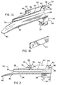
- Figure 1A is perspective view of a laryngoscope blade assembly in accordance with teachings of the invention.
- FIG. 1B is a perspective view of the protective insert of the blade assembly of FIG. 1A.
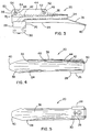
- FIG. 2 is a right plan view of the blade assembly of FIG. 1.
- FIG. 3 is a left plan view of the blade assembly of FIG. 1.
- FIG. 4 is an elevational view of the blade assembly of FIG. 1.
- FIG. 5 is a bottom view of the blade assembly of FIG. 1.
- FIG. 6 is an enlarged end view of the blade assembly of FIG. 1.
- FIG. 7 is an enlarged view of the blade assembly of FIG. 1 from the opposite end as that shown in FIG. 6.
- FIG. 8 is a perspective view of the blade assembly of FIG. 1 coupled to a laryngoscope handle.
- FIG. 9 is a side view of the laryngoscope of blade assembly of FIG. 8 as properly positioned in a patient to be intubated.
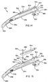
- FIG. 10 is a perspective view of an alternate embodiment of a laryngoscope blade assembly constructed in accordance with teachings of the invention.
- FIG. 11 is an exploded perspective view of the embodiment shown in FIG. 10.
- FIG. 12 is a perspective view of a second alternate embodiment of a laryngoscope blade assembly constructed in accordance with teachings of the invention.
- FIG. 13 is an exploded perspective view of the embodiment shown in FIG. 12.
- FIG. 14 is a perspective view of a third alternate embodiment of a laryngoscope blade assembly constructed in accordance with teachings of the invention.
- FIG. 15 is an exploded perspective view of the embodiment shown in FIG. 14.
- FIG. 16a is a fragmentary plan view of an alternate structure for coupling the protective insert to a laryngoscope blade.
- FIG. 16b is a cross-sectional view of the structure taken along line 16b-16b in FIG. 16a.
- FIG. 16c is a fragmentary plan view of a second alternate structure for coupling the protective insert to a laryngoscope blade.
- FIG. 16d is a cross-sectional view of the structure taken along line 16d-16d in FIG. 16c.
- FIG. 16e is a fragmentary plan view of a third alternate structure for coupling the protective insert to a laryngoscope blade.
- FIG. 16f is a cross-sectional view of the structure taken along line 16f-16f in FIG. 16e.
- FIG. 16g is a fragmentary plan view of a fourth alternate structure for coupling the protective insert to a laryngoscope blade.
- FIG. 16h is a cross-sectional view of the structure taken along line 16h-16h in FIG. 16g.
- FIGS. 1A through 9 a laryngoscope blade assembly 20 constructed in accordance with teachings of the invention, the laryngoscope blade assembly 20 shown assembled to a handle 22, which houses a power supply (not visible) generally in the form of batteries, in FIGS. 8 and 9.
- the blade assembly 20 comprises a unitary blade structure 24 and a base portion 26.
- the base portion 26 is of a conventional design, having a block 28 and a hook 30 for mating with a handle 22 in the customary manner.
- the handle 22 includes a pin 32 (visible in FIG. 8) which the hook 30 engages to couple the blade assembly 20 to the handle 22.
- the laryngoscope is provided with a light.
- the light is housed in the handle 22 and is transmitted toward the end of the blade (see point 34) by fiber optics (not visible), the wiring being carried in a channel 35 (FIG. 1A) formed in the blade structure 24 and the base portion 26 (FIG. 3) although other light sources may likewise be used.
- the electrical connection is made when the laryngoscope blade assembly 20 is assembled onto a handle 22.
- the blade structure 24 includes an elongated blade 36 and a tongue deflector 38.
- the blade 36 and tongue deflector 38 are formed as a single unit from a rigid material such as plastic or surgical or stainless steel. As seen most clearly in FIGS. 2 and 3, the blade 36 is substantially flat, having a slight bend downward toward the handle 22 at its distal end 40. The slight bend at the distal end 40 facilitates easy picking and lifting of the epiglottis during blade insertion. Alternately, the distal end may be placed along the pharyngeal side of the epiglottis, as with Macintosh blades.
- the tongue deflector 38 extends upward from the blade 36 in a smooth arc at a substantially right angle, as shown in FIGS. 6 and 7. Those skilled in the art will appreciate that the curve of the blade structure 24 is substantially more open than those of the Miller or Wisconsin style blades, and, accordingly, facilitates easy passage and placement of an endotracheal tube.
- the blade structure 24 is provided with means for protecting the patient's upper teeth from damage during intubation procedures.
- the tongue deflector 38 includes an elongated opening 42 along which a protective insert 44 is disposed. During use, the elongated opening 42 and protective insert 44 are disposed adjacent the patient's upper teeth 46, as shown in FIG. 9. Further, when the laryngoscope blade assembly 20 is properly positioned within the patient's glottis, the patient's teeth 46 may bear down on the resilient protective insert 44, minimizing any possibility of damaging the patient's dentition.
- the protective insert 44 is made of a resilient material, preferably a polymeric or rubber material, and has an flat, substantially rectangular shape.
- the protective insert 44 is coupled to the tongue deflector 38 at its distal and proximal ends 48, 50.
- This unique structure of the insert 44, as well as the method of coupling the protective insert 44 to the tongue deflector 38, provide for a particularly effective method of protecting the patient's teeth. As the patient's upper teeth bear down on the insert 44, the central section of the insert 44 may deflect as shown in FIG. 9, while still providing effective support.
- the method of attaching the protective insert 44 to the tongue deflector 38 preferably permits some minor movement of the insert 44 relative to the deflector 38.
- the structure of the protective insert 44 and its relationship to the tongue deflector 38 facilitates the inclusion of a tongue deflector 38 which is substantially vertical to the blade 36 of the blade assembly 20, while still providing effective protection to the patient's teeth.
- the thin structure of both the tongue deflector 38 and the protective insert 44, the laryngoscope blade assembly 20 occupies a minimal amount of space within the patient's mouth, providing a clear passage for the endotracheal tube during intubation.
- the protective insert 44 is removably coupled to the tongue deflector 38.
- the protective insert 44 is coupled to the tongue deflector 38 by snaps 52, 54, as seen most clearly in FIGS. 1A, 1B and 6.
- the snaps 52, 54 include enlarged bulbs 56, 58 which are interference fit with mating openings 62, 64 in the tongue deflector 38. In this way, the protective insert 44 may be "snapped" onto the tongue deflector 38.
- the snaps 52, 54 and openings 62, 64 provide a structure of coupling the protective insert 44 to the tongue deflector 38 which is secure, yet the protective insert 44 is readily removable to permit sterilization of the blade assembly 20 by conventional methods.
- the snaps 52, 54 themselves include two components, a male rivet portion 66 and a female bulb portion 70.
- the snaps 52, 54 are assembled to the protective insert 44 by mating the extension 68 of the male rivet portion 66, disposed along one side of the protective insert 44, with the interior of the bulb 56, 58 of the female bulb portion 70, disposed along the opposite side of the protective insert 44.
- the extension 68 is then deformed within the bulb 56, 58 to couple the components 66, 70 of the snap 52, 54 together.
- the tongue deflector includes a flange extending either inwardly or outwardly from the vertical portion of the tongue deflector.
- the surfaces of both the vertical portion of the tongue deflector and the flange must be interrupted such that the protective insert may be vertically deflected as the patient's teeth bear down on the protective insert.
- the Macintosh blade style may be modified to include a protective insert 44a and tongue deflector 38a constructed in accordance with teachings of the invention (see FIGS. 10 and 11).
- the tongue deflector 38a has been modified to include an opening 42a in its central portion.
- both the outwardly extending flange 39a, as well as the vertical portion 37a of the tongue deflector 38a are "cut out" or interrupted to provide a recess 42a.
- the patient's teeth bear down on the protective insert 44a, which may then be deflected into the opening 42a in the tongue deflector 38a.
- the protective insert 44a is removably coupled to the tongue deflector 38a at its distal and proximal ends 48a, 50a.
- a rivet 66a and bulb portion 70a are assembled through the protective insert 44a, the bulb 66a of the snap 52a may then be removably coupled to the flange 39a by means of the opening 62a therein.
- the Wisconsin and Miller style blades which have inwardly extending flanges 39b, 39c may likewise be modified to include protective inserts 44b, 44c constructed in accordance with teachings of the invention (see FIGS. 12 and 13, and FIGS. 14 and 15, respectively).
- both the inwardly extending flange 39b, 39c, and the substantially vertically extending portion 37b, 37c of the tongue deflectors 38b, 38c are cut out to provide travel for the protective inserts 44b, 44c should the patient's teeth bear down on the laryngoscope blade during use.
- the protective insert 44d may be provided with button-like structures 52d having a small diameter stem with a relatively larger diameter head which insert and slidingly mate with keyhole-shaped opening 62d in the tongue deflector 38d as shown in FIGS. 16a and 16b.
- button-like structures 52d having a small diameter stem with a relatively larger diameter head which insert and slidingly mate with keyhole-shaped opening 62d in the tongue deflector 38d as shown in FIGS. 16a and 16b.
- the protective insert may be provided with a post 52e which has a slightly larger diameter than the small portion of the keyhole-shaped opening 62e, as shown in FIGS. 16c and 16d.
- the post 52e may be inserted into the larger portion of the keyhole-shaped opening 62e and then forced sideways into the smaller portion of the keyhole-shaped opening 62e.
- a snap-like structure 52f is formed directly onto the plastic of the protective insert 44f, as shown in FIGS. 16e and 16f.
- the female bulb portion 70f of the snap 52f is only slightly larger than the opening 62f such that the protective insert 44f may be easily snapped into position in a manner similar to that shown in FIGS. 1a through 15.
- the snap 52g may have a sectioned structure, such as is shown in FIGS. 16g and 16h. It will be appreciated that in this embodiment, the sections of the snap 52g are resilient such that they may be elastically deformed as the snap 52g is progressed through the opening 62g and then return to their original expanded position to secure the protective insert 44g to the tongue deflector 38g.
- the invention provides a design for a laryngoscope blade assembly which minimizes or prevents possible damage to a patient's upper teeth during intubation procedures.
- the blade assembly includes a tongue deflector which is interrupted, or recessed along the position at which the patient's teeth are positioned when the laryngoscope is properly positioned within the patient's oral cavity.
- An elongated, thin, resilient protective insert is removably coupled to the tongue deflector along opposite sides of the recess, and may be removed for sterilization procedures.
- the thin profile of the insert takes minimal additional space within the patient's mouth and does not obstruct the path of the endotracheal tube.
- the protective insert may deflect if the patient's teeth bear down during an intubation procedure, it is not necessary that the blade assembly include a flange.
- the preferred embodiment of the blade includes a substantially vertical tongue deflector having no flange which might take up additional space in the patient's mouth or obstruct the pathway of an endotracheal tube.
Landscapes
- Health & Medical Sciences (AREA)
- Life Sciences & Earth Sciences (AREA)
- Surgery (AREA)
- Radiology & Medical Imaging (AREA)
- Engineering & Computer Science (AREA)
- Pulmonology (AREA)
- Biophysics (AREA)
- Nuclear Medicine, Radiotherapy & Molecular Imaging (AREA)
- Optics & Photonics (AREA)
- Pathology (AREA)
- Physiology (AREA)
- Otolaryngology (AREA)
- Physics & Mathematics (AREA)
- Biomedical Technology (AREA)
- Heart & Thoracic Surgery (AREA)
- Medical Informatics (AREA)
- Molecular Biology (AREA)
- Animal Behavior & Ethology (AREA)
- General Health & Medical Sciences (AREA)
- Public Health (AREA)
- Veterinary Medicine (AREA)
- Endoscopes (AREA)
Applications Claiming Priority (2)
| Application Number | Priority Date | Filing Date | Title |
|---|---|---|---|
| US843437 | 1986-03-24 | ||
| US08/843,437 US5776053A (en) | 1997-04-15 | 1997-04-15 | Laryngoscope blade with protective insert |
Publications (1)
| Publication Number | Publication Date |
|---|---|
| EP0872209A1 true EP0872209A1 (de) | 1998-10-21 |
Family
ID=25289970
Family Applications (1)
| Application Number | Title | Priority Date | Filing Date |
|---|---|---|---|
| EP98302845A Withdrawn EP0872209A1 (de) | 1997-04-15 | 1998-04-14 | Laryngoskopspatel mit Schutzeinsatz |
Country Status (2)
| Country | Link |
|---|---|
| US (1) | US5776053A (de) |
| EP (1) | EP0872209A1 (de) |
Cited By (1)
| Publication number | Priority date | Publication date | Assignee | Title |
|---|---|---|---|---|
| EP3430971A1 (de) | 2017-07-19 | 2019-01-23 | Universität Zürich | Medizinische vorrichtung mit einer zahnschützenden vorrichtung für orale intubationseingriffe |
Families Citing this family (27)
| Publication number | Priority date | Publication date | Assignee | Title |
|---|---|---|---|---|
| US5984863A (en) * | 1998-05-15 | 1999-11-16 | Ansari; Mohammed A. | Pediatric laryngoscopic blade |
| US6623425B2 (en) * | 2001-07-23 | 2003-09-23 | Cartledge Medical Products, Llc | Modified laryngoscope blade to reduce dental injuries during intubation |
| US7608040B1 (en) | 2003-02-24 | 2009-10-27 | City Of Hope | Device to aid in placing tracheal tubes |
| US7458932B2 (en) * | 2003-12-09 | 2008-12-02 | Sun William Y | Tongue stabilizer for laryngoscope blade |
| US7744529B2 (en) | 2004-02-12 | 2010-06-29 | Carl Kaoru Sakamoto | Laryngoscope blade |
| US7736304B2 (en) * | 2004-02-29 | 2010-06-15 | Truphatek International Ltd. | Metal laryngoscope blade |
| US8142353B2 (en) * | 2004-02-29 | 2012-03-27 | Truphatek International Ltd. | Metal laryngoscope blade with illumination assembly |
| US20050240081A1 (en) * | 2004-04-22 | 2005-10-27 | The Cleveland Clinic Foundation | Laryngoscope blade |
| US20060183978A1 (en) * | 2005-02-14 | 2006-08-17 | Howard Gregory L | Laryngoscope |
| US20070197876A1 (en) * | 2006-02-17 | 2007-08-23 | Lane Edward D | Dental guard for airway intubation |
| US8235892B2 (en) * | 2006-04-07 | 2012-08-07 | Eduardo Salcedo | Laryngoscope dental protection device |
| US7955256B2 (en) * | 2006-08-04 | 2011-06-07 | Carl Kaoru Sakamoto | Laryngoscope blade |
| US7695433B2 (en) * | 2007-01-24 | 2010-04-13 | Zeppelin Designs, Inc. | Laryngoscope with disposable blade cover |
| IL185112A0 (en) * | 2007-08-07 | 2008-01-06 | Truphatek Int Ltd | Laryngoscope apparatus |
| US8998804B2 (en) * | 2008-11-12 | 2015-04-07 | Board Of Regents Of The University Of Nebraska | Suction catheter assembly for a laryngoscope |
| US9289114B2 (en) * | 2010-07-30 | 2016-03-22 | Nilesh R. Vasan | Disposable, self-contained laryngoscope and method of using same |
| IL212204A0 (en) | 2011-04-07 | 2011-06-30 | Truphatek Int Ltd | Laryngoscope assembly with enhanced viewing capability |
| US10231612B2 (en) * | 2012-07-31 | 2019-03-19 | Vincent Nacouzi | Laryngoscope |
| ITCT20130005A1 (it) * | 2013-02-21 | 2014-08-22 | Francesco Sgalambro | Lama curva per laringoscopio con supporto guida per broncoscopio flessibile.lama beb(bronchoscopy easy blade) |
| US20170079518A1 (en) * | 2014-03-11 | 2017-03-23 | Truphatek International Ltd. | Metal laryngoscope blade with non-metal safety tip |
| USD766431S1 (en) * | 2014-07-07 | 2016-09-13 | Evgeny Pecherer | Laryngoscope handle |
| US10238373B1 (en) * | 2016-03-11 | 2019-03-26 | Colorado Voice Clinic, P.C. | Retractor |
| US10349823B2 (en) * | 2016-03-11 | 2019-07-16 | Colorado Voice Clinic, P.C. | Retractor and tip extender therefor |
| USD866759S1 (en) | 2017-03-13 | 2019-11-12 | Colorado Voice Clinic, P.C. | Retractor |
| CN112930134B (zh) * | 2018-07-30 | 2025-10-28 | 泰利福医疗公司 | 带光导的喉镜刀片 |
| USD876625S1 (en) | 2018-08-07 | 2020-02-25 | Adroit Surgical, Llc | Laryngoscope |
| EP4216790A1 (de) * | 2020-09-23 | 2023-08-02 | Flexicare (Group) Limited | Intubationsvorrichtung und -system |
Citations (6)
| Publication number | Priority date | Publication date | Assignee | Title |
|---|---|---|---|---|
| US3826248A (en) | 1971-09-21 | 1974-07-30 | G Gobels | Laryngoscope |
| US4295465A (en) * | 1980-04-03 | 1981-10-20 | N.A.D., Inc. | Laryngoscope blade |
| US4583527A (en) | 1984-12-24 | 1986-04-22 | Musicant Belmont S | Disposable cushioning device for a laryngoscope |
| US5063907A (en) | 1989-06-14 | 1991-11-12 | Musicant Belmont S | Disposable and/or sterilizable cushioning device for a laryngoscope |
| US5065738A (en) | 1990-01-16 | 1991-11-19 | Dam David J Van | Laryngoscope blade sheath |
| US5438976A (en) | 1993-11-29 | 1995-08-08 | Nash; Jeanne L. | Teeth protector for laryngoscope blade |
Family Cites Families (2)
| Publication number | Priority date | Publication date | Assignee | Title |
|---|---|---|---|---|
| US4112933A (en) * | 1977-01-21 | 1978-09-12 | Moses John A | Laryngoscope of the straight blade type |
| US4570614A (en) * | 1983-05-06 | 1986-02-18 | Jack Bauman | Laryngoscope with disposable blade and light conductor |
-
1997
- 1997-04-15 US US08/843,437 patent/US5776053A/en not_active Expired - Fee Related
-
1998
- 1998-04-14 EP EP98302845A patent/EP0872209A1/de not_active Withdrawn
Patent Citations (6)
| Publication number | Priority date | Publication date | Assignee | Title |
|---|---|---|---|---|
| US3826248A (en) | 1971-09-21 | 1974-07-30 | G Gobels | Laryngoscope |
| US4295465A (en) * | 1980-04-03 | 1981-10-20 | N.A.D., Inc. | Laryngoscope blade |
| US4583527A (en) | 1984-12-24 | 1986-04-22 | Musicant Belmont S | Disposable cushioning device for a laryngoscope |
| US5063907A (en) | 1989-06-14 | 1991-11-12 | Musicant Belmont S | Disposable and/or sterilizable cushioning device for a laryngoscope |
| US5065738A (en) | 1990-01-16 | 1991-11-19 | Dam David J Van | Laryngoscope blade sheath |
| US5438976A (en) | 1993-11-29 | 1995-08-08 | Nash; Jeanne L. | Teeth protector for laryngoscope blade |
Cited By (2)
| Publication number | Priority date | Publication date | Assignee | Title |
|---|---|---|---|---|
| EP3430971A1 (de) | 2017-07-19 | 2019-01-23 | Universität Zürich | Medizinische vorrichtung mit einer zahnschützenden vorrichtung für orale intubationseingriffe |
| WO2019015944A1 (en) | 2017-07-19 | 2019-01-24 | Universität Zürich | MEDICAL DEVICE COMPRISING A DENTAL PROTECTIVE DEVICE FOR ORAL INTUBATION PROCEDURES |
Also Published As
| Publication number | Publication date |
|---|---|
| US5776053A (en) | 1998-07-07 |
Similar Documents
| Publication | Publication Date | Title |
|---|---|---|
| US5776053A (en) | Laryngoscope blade with protective insert | |
| US5888195A (en) | Laryngoscope blade | |
| US5261392A (en) | Laryngoscope with interchangeable fiberoptic assembly | |
| US5183031A (en) | Fiberoptic intubating laryngoscope | |
| US10349822B2 (en) | Guiding device for use with laryngoscope | |
| US5327881A (en) | Fiberoptic intubating stylet | |
| JP3068652B2 (ja) | 喉頭鏡 | |
| US4437458A (en) | Laryngoscope | |
| JPH05501660A (ja) | 経口的な喉頭および食道の盲操作案内および照準装置 | |
| US4611579A (en) | Laryngoscope | |
| US20090090357A1 (en) | Guide device for tracheal intubation | |
| US20140336466A1 (en) | Guiding device for use with laryngoscope | |
| CN112930134B (zh) | 带光导的喉镜刀片 | |
| CA1167338A (en) | Laryngoscope | |
| US7955256B2 (en) | Laryngoscope blade | |
| US20200060538A1 (en) | Laryngoscope | |
| US20240366081A1 (en) | Laryngoscope and uses thereof |
Legal Events
| Date | Code | Title | Description |
|---|---|---|---|
| PUAI | Public reference made under article 153(3) epc to a published international application that has entered the european phase |
Free format text: ORIGINAL CODE: 0009012 |
|
| AK | Designated contracting states |
Kind code of ref document: A1 Designated state(s): AT BE CH CY DE DK ES FI FR GB GR IE IT LI LU MC NL PT SE |
|
| AX | Request for extension of the european patent |
Free format text: AL;LT;LV;MK;RO;SI |
|
| STAA | Information on the status of an ep patent application or granted ep patent |
Free format text: STATUS: THE APPLICATION HAS BEEN WITHDRAWN |
|
| 18W | Application withdrawn |
Withdrawal date: 19990215 |