EP0872217A1 - Medizinisches oder dentalmedizinisches Behandlungsinstrument zur spanabhebenden Bearbeitung von Körpergewebe oder einem Ersatzstoff mit einem abrasiven Werkzeug - Google Patents
Medizinisches oder dentalmedizinisches Behandlungsinstrument zur spanabhebenden Bearbeitung von Körpergewebe oder einem Ersatzstoff mit einem abrasiven Werkzeug Download PDFInfo
- Publication number
- EP0872217A1 EP0872217A1 EP98106881A EP98106881A EP0872217A1 EP 0872217 A1 EP0872217 A1 EP 0872217A1 EP 98106881 A EP98106881 A EP 98106881A EP 98106881 A EP98106881 A EP 98106881A EP 0872217 A1 EP0872217 A1 EP 0872217A1
- Authority
- EP
- European Patent Office
- Prior art keywords
- treatment instrument
- medical
- instrument according
- handpiece
- medical treatment
- Prior art date
- Legal status (The legal status is an assumption and is not a legal conclusion. Google has not performed a legal analysis and makes no representation as to the accuracy of the status listed.)
- Granted
Links
Images




Classifications
-
- A—HUMAN NECESSITIES
- A61—MEDICAL OR VETERINARY SCIENCE; HYGIENE
- A61B—DIAGNOSIS; SURGERY; IDENTIFICATION
- A61B17/00—Surgical instruments, devices or methods
- A61B17/16—Instruments for performing osteoclasis; Drills or chisels for bones; Trepans
- A61B17/1613—Component parts
- A61B17/1626—Control means; Display units
-
- A—HUMAN NECESSITIES
- A61—MEDICAL OR VETERINARY SCIENCE; HYGIENE
- A61B—DIAGNOSIS; SURGERY; IDENTIFICATION
- A61B17/00—Surgical instruments, devices or methods
- A61B17/16—Instruments for performing osteoclasis; Drills or chisels for bones; Trepans
- A61B17/1613—Component parts
- A61B17/1622—Drill handpieces
-
- A—HUMAN NECESSITIES
- A61—MEDICAL OR VETERINARY SCIENCE; HYGIENE
- A61C—DENTISTRY; APPARATUS OR METHODS FOR ORAL OR DENTAL HYGIENE
- A61C1/00—Dental machines for boring or cutting ; General features of dental machines or apparatus, e.g. hand-piece design
- A61C1/02—Dental machines for boring or cutting ; General features of dental machines or apparatus, e.g. hand-piece design characterised by the drive of the dental tools
- A61C1/05—Dental machines for boring or cutting ; General features of dental machines or apparatus, e.g. hand-piece design characterised by the drive of the dental tools with turbine drive
- A61C1/052—Ducts for supplying driving or cooling fluid, e.g. air, water
-
- A—HUMAN NECESSITIES
- A61—MEDICAL OR VETERINARY SCIENCE; HYGIENE
- A61C—DENTISTRY; APPARATUS OR METHODS FOR ORAL OR DENTAL HYGIENE
- A61C1/00—Dental machines for boring or cutting ; General features of dental machines or apparatus, e.g. hand-piece design
- A61C1/02—Dental machines for boring or cutting ; General features of dental machines or apparatus, e.g. hand-piece design characterised by the drive of the dental tools
- A61C1/07—Dental machines for boring or cutting ; General features of dental machines or apparatus, e.g. hand-piece design characterised by the drive of the dental tools with vibratory drive, e.g. ultrasonic waves
-
- A—HUMAN NECESSITIES
- A61—MEDICAL OR VETERINARY SCIENCE; HYGIENE
- A61C—DENTISTRY; APPARATUS OR METHODS FOR ORAL OR DENTAL HYGIENE
- A61C1/00—Dental machines for boring or cutting ; General features of dental machines or apparatus, e.g. hand-piece design
- A61C1/08—Machine parts specially adapted for dentistry
-
- A—HUMAN NECESSITIES
- A61—MEDICAL OR VETERINARY SCIENCE; HYGIENE
- A61B—DIAGNOSIS; SURGERY; IDENTIFICATION
- A61B17/00—Surgical instruments, devices or methods
- A61B17/16—Instruments for performing osteoclasis; Drills or chisels for bones; Trepans
- A61B17/1613—Component parts
- A61B17/1622—Drill handpieces
- A61B17/1624—Drive mechanisms therefor
-
- A—HUMAN NECESSITIES
- A61—MEDICAL OR VETERINARY SCIENCE; HYGIENE
- A61B—DIAGNOSIS; SURGERY; IDENTIFICATION
- A61B17/00—Surgical instruments, devices or methods
- A61B17/16—Instruments for performing osteoclasis; Drills or chisels for bones; Trepans
- A61B17/1613—Component parts
- A61B17/1633—Sleeves, i.e. non-rotating parts surrounding the bit shaft, e.g. the sleeve forming a single unit with the bit shaft
-
- A—HUMAN NECESSITIES
- A61—MEDICAL OR VETERINARY SCIENCE; HYGIENE
- A61B—DIAGNOSIS; SURGERY; IDENTIFICATION
- A61B17/00—Surgical instruments, devices or methods
- A61B17/16—Instruments for performing osteoclasis; Drills or chisels for bones; Trepans
- A61B17/1659—Surgical rasps, files, planes, or scrapers
-
- A—HUMAN NECESSITIES
- A61—MEDICAL OR VETERINARY SCIENCE; HYGIENE
- A61B—DIAGNOSIS; SURGERY; IDENTIFICATION
- A61B90/00—Instruments, implements or accessories specially adapted for surgery or diagnosis and not covered by any of the groups A61B1/00 - A61B50/00, e.g. for luxation treatment or for protecting wound edges
- A61B90/03—Automatic limiting or abutting means, e.g. for safety
- A61B2090/031—Automatic limiting or abutting means, e.g. for safety torque limiting
-
- A—HUMAN NECESSITIES
- A61—MEDICAL OR VETERINARY SCIENCE; HYGIENE
- A61B—DIAGNOSIS; SURGERY; IDENTIFICATION
- A61B90/00—Instruments, implements or accessories specially adapted for surgery or diagnosis and not covered by any of the groups A61B1/00 - A61B50/00, e.g. for luxation treatment or for protecting wound edges
- A61B90/36—Image-producing devices or illumination devices not otherwise provided for
-
- A—HUMAN NECESSITIES
- A61—MEDICAL OR VETERINARY SCIENCE; HYGIENE
- A61C—DENTISTRY; APPARATUS OR METHODS FOR ORAL OR DENTAL HYGIENE
- A61C1/00—Dental machines for boring or cutting ; General features of dental machines or apparatus, e.g. hand-piece design
- A61C1/08—Machine parts specially adapted for dentistry
- A61C1/18—Flexible shafts; Clutches or the like; Bearings or lubricating arrangements; Drives or transmissions
- A61C1/185—Drives or transmissions
- A61C1/186—Drives or transmissions with torque adjusting or limiting means
Definitions
- the invention relates to a medical or dental medicine Treatment instrument according to the preamble of claim 1, 5, 19, 25 or 27.
- treatment instruments For machining body tissue or a substitute (tissue replacement or a prosthesis) are treatment instruments with an abrasive tool and a vibration drive, preferably in the acoustic or ultrasonic range frequency known.
- a treatment tool is e.g. in the WO 96/14024. It has an elongated handpiece in the form of a sleeve Housing on, in the front region of a vibrating part resiliently mounted is that can be set in vibration by a vibration exciter during operation is and in its front area by a holding device with the tool is connectable.
- the handpiece has a coupling part, in particular a screw or plug-in coupling part with which it is connected with a so-called Connection piece of a supply device can be coupled in the form of a flexible hose is, which extends to a supply and control device and media lines to Energy supply and supply of treatment media such as Water, air or a spray.
- a coupling part in particular a screw or plug-in coupling part with which it is connected with a so-called Connection piece of a supply device can be coupled in the form of a flexible hose is, which extends to a supply and control device and media lines to Energy supply and supply of treatment media such as Water, air or a spray.
- a treatment instrument of this type can also be used in the dental field Use a tartar removal device, one from the Austrian Patent 379 505 known treatment instrument a tool with a has wedge-shaped working tip.
- the known treatment instruments are based on a vibration function specific type of tool or tailored to a specific machining process. This is the range of use of such a treatment instrument is restricted.
- the invention has for its object a treatment instrument of the beginning to improve the specified type so that it is suitable for a wider range of applications is suitable.
- the vibration exciter is one Control device for increasing and decreasing its output power assigned, which enables a power setting in stages or continuously.
- the treatment instrument according to the invention is suitable for a wide range Range of applications, e.g. for processing with different tools, in particular different sizes and / or shapes and / or abrasion capacity (Abrasiveness) with which it can be optionally equipped.
- abrasion capacity Abrasiveness
- these Adjustments taking into account the same materials or different ones Materials of the tool and / or the material to be processed can be done.
- the configuration according to the invention also enables the Treatment instruments to different types of processing, e.g. to remove Coverings, as is the case with a tartar removal device, or for finishing a cavity, e.g. is the case when preparing a tooth.
- a medical or dental treatment instrument of the present type can be prone to malfunction in terms of its power output because of the vibration exciter should give a constant and certain vibration performance in order to achieve an optimal one Achieve vibration operation.
- the optimal vibration operation can be proportionate easily be affected by different performance sizes, although hardly too avoiding vibrational resonances have an adverse effect on the Can exercise vibration behavior. This is especially true for a Treatment instrument, the vibration exciter can be driven by compressed air.
- the invention is therefore based on a further object Treatment instrument of the type specified in the preamble of claim 5 to design that a constant vibration output is achieved.
- the treatment instrument is one Pressure controller assigned to the constant pending at the vibration exciter Working pressure. This ensures that with unavoidable Fluctuations in operating pressure, or when the treatment tool is on Treatment stations are used where there are different operating pressures (different manufacturers) the vibration performance remains the same and therefore an optimal one Vibration operation can be maintained.
- the Vibration exciter pneumatically driven by compressed air the vibration can generate the vibrating part by a vibrating part, which when flowing through the Compressed air vibrates and its vibrations through the vibrating part mechanical impact transmits.
- a vibration exciter arise Noises that can be considerable and disturb the practitioner.
- the invention is therefore based on the object in one Treatment instrument of the type specified in the preamble of claim 19 Reduce drive noise.
- the vibrating part is in an additional Encapsulated inner housing, which significantly dampens the drive noise and not bother the user or not significantly.
- the Design according to the invention by a simple, small, inexpensive to produce and easy to assemble or disassemble.
- the invention is further based on the object of a treatment instrument the type specified in the preamble of claim 25 an impairment of the teeth to avoid or reduce when touched by the handpiece shaft.
- the handpiece shaft has a protective jacket made of elastic compliant material on, which the aforementioned impairment in simple and avoids cost-effectively.
- the protective jacket can also serve the elastic mounting of the vibrating part in the front end area of the handpiece stabilize
- the elastic flexible storage of the vibrating part in the front end area of the handpiece is essential stabilized, while also an elastically compliant and therefore gentle Storage for an optical fiber is created, which significantly increases the risk of breakage reduced.
- the main parts of the treatment instrument are one elongated or rod-shaped handpiece 2 with a grip sleeve 3, in which a preferably elongated or rod-shaped vibrating part 4 is mounted so that it can vibrate and by a Vibration exciter 5 can be set in vibration or driven, and a Holding device 6 for at least one treatment tool 7, the one Tool shaft 8, which is releasably connectable to the holding device 6.
- a light guide 9 is provided which extends lengthwise through the Handpiece 2 extends into its front end area and at one on the Treatment site directed mouth opening 11, and a Illuminating device 12 forms.
- a treatment or cooling liquid here water
- a treatment or cooling liquid here water
- a supply line 15 for drive energy is provided, which runs lengthways through the handpiece 2 extends to drive the vibration exciter 5.
- a vibration exciter 5 that can be driven by compressed air provided and the supply line 15 is a compressed air line, which extends to Vibration exciter 5 extends.
- the handpiece 2 is by a quick coupling or by a screw or Plug-in coupling, in particular by means of a freely rotatable plug-in rotary coupling 16, on the back with an indicated connector 17 releasably connectable by a flexible Supply line 18 with a supply and control device, not shown connected is.
- the plug-in rotary coupling 16 is through in the present embodiment a hollow cylindrical or stepped hollow cylindrical coupling recess 16a and one cylindrical or step-cylindrical insertable with play Coupling pin 16b formed, which in the present embodiment Coupling recess 16a is arranged in the rear area of the handpiece 2 and the Coupling pin 16b protrudes from the connector 17.
- the light guide 9 passes through the plug-in rotary coupling 16 coaxially.
- the front light guide section is preferred through a light guide 9a made of light-conducting material, e.g. Glass or plastic, formed, which is a flexible light guide or a rigid light guide in Can act shape of a fitting.
- the cross-sectional shape of the light guide 9 is preferably round at the back and elliptical at the front.
- the light guide section can also be through a light guide, not shown, or through an electrical line with one in the front end region of the coupling pin 16b arranged lamp 19 may be formed in a front open recess is preferably arranged sunk.
- the other two media lines 13, 15 pass through the hollow cylindrical parting line 21 between the coupling pin 16b and the wall of the coupling recess 16a Z-shaped radially from the inside out, each in the outer surface of the Coupling pin 16a and the inner surface of the coupling recess 16b existing openings in an annular groove 22 in the lateral surface or in the Inner surface.
- the Z-shaped Penetration points are each by a sealing ring 23, in particular an O-ring, sealed, on both sides of the Z-shaped penetration point in one Ring groove in the outer surface of the coupling pin 16b or in the inner surface of the Coupling recess 16a is arranged.
- Connections e.g. Connection sleeves 24, for in the flexible supply line 18th extending media line sections may be arranged.
- the holding device 6 for the tool 7 is in the front end region of the oscillating part 4 arranged.
- the vibrating part 4 is a rod or sleeve-shaped body which is arranged in the front half of the handpiece 2 and forms a handpiece shaft 25 which projects from the front end of the handpiece 2 and can extend straight or with respect to the longitudinal central axis 26 of the handpiece 2 can include an acute angle W of approximately 10 to 30 °, in particular approximately 20 °.
- the holding device 6 has a transverse or preferably perpendicular to Handpiece shaft 25 extending plug hole 27, which is preferably a blind hole and is therefore only open on one side, and in which the tool shank 8 with a small Movement play is insertable.
- a securing recess 28 is provided in the tool shank 8, into which a securing part 29 adjustable in the longitudinal direction of the handpiece shaft 25 can be moved in, which moved between it into the securing recess 28 Secure position and a moved out, the tool shank 8 releasing Release position is adjustable and preferably by the force of a spring in it Secure position is applied.
- the securing recess 28 can be to trade an annular groove.
- There can also be several, evenly distributed over the circumference arranged calottes are provided, which preferably have conical depressions can have a central core bore.
- the handpiece shaft 25 extending in the area of the handpiece 2 as a vibrating rod 4a is radially and preferably also axially flexible against elastic restoring forces or movably mounted in the handpiece 2.
- This is used in the front end area of the handpiece 2 a bearing sleeve 35 made of elastic material, e.g. Plastic or rubber, in whose Through hole 36 of the vibrating rod 4a is received with circumferential contact, so that it is centered by the bearing sleeve 35.
- the bearing sleeve 35 in its front and rear end region radially inwards projecting, preferably rounded in cross section bearing beads 37 between which is arranged an annular gap 38 surrounding the vibrating rod 4a.
- the bearing sleeve 35 can be fixed in a sleeve cap 39, which is fixed with a sleeve housing 41 connected, e.g. is screwed into it, as shown in FIG. 1, and the circumferential side Completely complete with each other and form the grip sleeve 3.
- the bearing sleeve 35 projects beyond the sleeve housing 41 or the sleeve cap 39 and forms thus a protective jacket 35a for the handpiece shaft 25, which extends up to or into the Near the holding device 6 or an actuator 92a to be described extends.
- a protective jacket 35a for the handpiece shaft 25 which extends up to or into the Near the holding device 6 or an actuator 92a to be described extends.
- the bearing sleeve 35 and or the protective jacket 35a is one positive connection 40 with an annular groove 40a and a bordering therein Ring pin 40b provided, which due to the elastically deformable material Plug in automatically. Due to the outstanding elastic or soft elastic Protective sheaths 35a are caused by the vibration during the treatment Impairment in contacting the tool shank with neighboring ones Body parts, e.g. Teeth, avoided.
- the protective jacket also be arranged and fixed as a separate component only on the tool shank 25, for. B. then pushed on elastically or by means of a corresponding
- the bearing ring 42 made of elastically deformable Material such as plastic or rubber, in particular an O-ring, formed in which the Vibrating rod 4a sits with outside contact, the bearing ring 42 in one Vibrating rod 4a with a radial annular space 43a surrounding sleeve 43 or in one of the latter is received and stored in the rearwardly extending bearing part 44, which or that in the sleeve housing 41 radially and axially immovable or preferably against one Restoring force is movably mounted, in particular inserted from behind and with a front shoulder surface on a rear shoulder surface of the Sleeve housing 41 abuts.
- the bearing part 44 has a front sleeve extension 45 on, which surrounds the vibrating rod 4a with a radial distance, the rear end of the Vibrating rod 4a ends in a free space 46 of the bearing part 44.
- the front sleeve approach 45 is connected to the sleeve 43 in an overlapping arrangement, preferably then plugged in or plugged in and sealed by a seal, which is shown here by the Bearing ring 42 is formed.
- the vibrating rod 4a can be coaxial with the associated bearing elements Longitudinal central axis 26 may be arranged.
- the Longitudinal central axis 26a of the vibrating rod 4a with respect to the longitudinal central axis of the front End region of the grip sleeve 3 and the bearing sleeve 35 for the laterally arranged Tool body 8a facing away from the side and thus arranged eccentrically, the outlet opening 11 and the associated through-channel 11a, in which the Light guide 9a is included, with respect to the vibrating rod 4a to the tool facing side is arranged here in the correspondingly eccentric bearing sleeve 35.
- the rear end of the light guide 9a is in a by means of a bearing sleeve 47 Extension of the coupling recess 16a arranged, the light guide 9a through an eccentric through-channel 44a in the bearing part 44 as laterally curved molded part extends forward.
- Bearing part 44 has an eccentric rear pipe socket 48, on the back one Sleeve projection 49a connects a coupling sleeve 49, which alone or with the Bearing part 44 as a composite component radially on all sides and axially against one Restoring force is movably mounted in the sleeve housing 41.
- At least one is used for this Coupling sleeve 49 surrounding bearing ring 51 made of elastically deformable material, which Coupling sleeve 49 centered due to its elastic restoring force and radially elastic resiliently stored.
- the bearing ring 51 preferably has a rear side Shoulder surface 52 engaging behind the inner flange 53, which the coupling sleeve 49 with respect to axial rearward movements resiliently resilient.
- the present embodiment is that through the coupling sleeve 49 and the bearing part 44 formed unit between the inner flange 53 and the bearing ring 42 in both axial Directions resiliently resilient.
- an axially and preferably also diametrically effective bearing ring 50 may be arranged from resilient material, wherein due to the elastic restoring force of the elastically flexible bearing elements Centering is guaranteed, both axially and diametrically.
- the Bearing ring 51 is positively fixed in the axial direction, e.g. in that Inner flange 53 on a forward shoulder surface one in the rear end of the sleeve housing 41 screwed threaded sleeve 54 abuts.
- the locking device 55 has a or more distributed over the circumference in radial holes of the coupling sleeve 49 arranged, preferably formed by balls locking elements formed, the so far into the holes that the radially inner ends of the Locking elements can snap into an annular groove in the coupling pin 16b.
- the locking elements automatically against a spring acting radially inwards in the form of a Spring washers 59 pressed out of the ring groove.
- the holes are at their inner ends tapered so that the locking element or elements, preferably balls with removed Coupling pin 16b cannot fall out inwards.
- the media lines extend in the connector 17 as e.g. axially parallel channels 13a, 15a, which are located in the associated transverse transverse plane in the form of angular channels continue in the coupling pin 16b and in the coupling sleeve 49, the one Cross-pass plane E1 with respect to the other cross-plane E2 of FIG Compressed air line is axially offset and the angle channels in the coupling sleeve 49 with 13b, 15b are designated.
- a pipe or hose 13c which is connected downstream with another pipe or Hose 13d is connected, which is a rear wall 44b of the bearing part 44 in a Bushing bushing 44c penetrates in a sealed manner and is located in the cavity 61 of the sleeve-shaped vibrating rod 4a extends into its central region, in which a End sleeve 62 sealed by means of one or two sealing rings 62a in the sleeve Vibrating rod 4a sits and is tightly connected to the tube 13d, especially on it is put on.
- the vibration exciter 5 is a control device for reducing or increasing associated with his performance. This allows its performance or Intensity of vibration or vibrations and the size of the amplitudes optionally reduce or enlarge and thus adjust.
- the manually operable adjusting device 73 has an adjusting member 74 which of manually accessible from the outside and adjustable axially or circumferentially and in Drive connection is established with the control device 72 or forms a control device.
- the adjusting member 74 is an adjusting sleeve 74a that Handpiece 2 preferably surrounds in the rear area and in particular in one an annular recess forming a ring guide 75 sunk and axially or is preferably adjustable in the circumferential direction.
- the ring recess 75 on the back through a shoulder surface of the screw-in sleeve 54 limited.
- a support web 76 projects radially from the inner circumferential surface of the adjusting sleeve 74a inward, which extends over part of the circumference and slots 77a, 77b in Sleeve housing 41 and the components arranged radially inward thereof, here in the Coupling sleeve 49 and in the bearing ring 51, grasped with play and on his inner end carries a segment 78 extending over a portion of the circumference, which has an inclined or curved surface 79 on one side, which with an adjusting member 81 cooperates, which is in operative connection with the control device 72, as it is Fig.3 shows schematically and Fig.1 and 2 as an embodiment.
- the oblique or Curve surface 79 can be arranged on segment 78 on the front and rear.
- the inclined or curved surface 79 is arranged on the front, and the adjusting member 81 is an axially parallel in a guide 82 slidably mounted Adjustment pin 81a by the force of a spring, here a compression spring against the oblique or Cam surface 79 is acted upon and thus this during a back and forth rotation of the actuator 74 is able to tap.
- the guide 82 can be axially parallel Bore in the rotationally mounted coupling sleeve 49 may be formed.
- the adjusting device 73 can be adjusted in steps or continuously. In both cases it is advantageous to assign a locking device 83 to the adjusting device 73 enables the setting device 73 to be locked in the respectively set position and thereby prevents unintentional adjustment. This can be a Act braking device that due to its stiffness an unintended Adjustment of the adjusting member 74 prevented.
- Lockable locking device 84 preferably with a ball formed, radially movably guided locking element 85 is provided, which at Turning the adjusting sleeve 74a in domes 86 can be manually pushed over and locked out, that on an outer surface of the coupling sleeve 49 in the circumferential direction are arranged one behind the other, here in the bottom of the groove or slot 77b.
- the locking element 85 can be radial in a radial bore in the support web 76 be slidably mounted and by a compression spring 88 arranged in the bore be biased against the calottes 86.
- the adjusting member 81 acts on it in its Performance adjustable vibration exciter 5, so that its performance with the Adjustment member 74 is either increased or decreased.
- the control device 72 can have a control valve 65 for the purpose of controlling the pressure p1 acting on the vibration exciter 5.
- Adjusting member 74 may be connected directly or indirectly to a valve slide 66, the size of a valve opening 67 depending on the setting of the Setting member 74 controls.
- the valve opening 67 is located in the supply line 15, here downstream of the coupling pin 16b in the area of the angle channel 15b.
- valve slide 66 is used to reduce the vibration power Adjustment device 73 moved in the sense of reducing the valve opening 67, in the present embodiment forward, so that the valve opening 67 on the Vibration exciter 5 pressure p1 in the sense of an adjustable throttle decreased.
- the valve opening 67 is reversed Senses increased, whereby a larger pressure p1 is set.
- the Return of the setting member 74 can be done by a return spring that the Preset 74 against the inclined or curved surface 79.
- valve slide 66 in the feed line 15, here in the axially parallel Feed line section 15b, arranged, preferably longitudinally displaceable therein mounted, the valve opening 67 through an end face of the valve spool 66 can be controlled.
- the valve spool 66 can also have a cup-shaped shape have, the valve opening 67 being arranged in the peripheral wall of the pot shape can.
- valve spool 66 is on one end of the effective pressure p1 is applied and on its other end face by means of a compression spring 68 biased opposite to its open position.
- valve slide 66 is a round or non-round cup-shaped sleeve with a bottom wall 66a at its end facing away from the vibration exciter 5.
- the valve opening 67 is in the radially inner peripheral wall 66b with the radial portion of the Feed line section 15b cooperatively arranged.
- valve slide 66 In the open position the valve slide 66 is tensioned by the spring 68 against a stop 66c, here the Pipe socket 48.
- a spring mandrel 66d extends rearward from the valve slide 66 which the compression spring 68 sits and against a rear abutment 69, here against Adjustment member 81 is supported.
- the compressed air flows from the supply line section 15b through the at the rear end existing annular gap in the cavity 61 of the sleeve-shaped Vibrating rod 4a, one or more in the central region and in front of the end sleeve 62 has radial and / or secantial flow-through holes 63, in the area of which Vibrating rod 4a with radial movement play from a wobble or vibration sleeve 64 is surrounded, which is arranged with axial movement play between two stops 64a , each of which is constituted by a ring of elastic material, e.g. an O-ring can be, which sits in an annular groove in the vibrating rod 4a.
- a ring of elastic material e.g. an O-ring can be
- the support ring 43b is axial fixed, here between a possibly conical shoulder surface on the vibrating rod 4a and an inner flange of the sleeve 43.
- the sleeve 43 forms an inner housing or one in conjunction with the support ring 43b Encapsulation of the vibration exciter 5, causing a substantial reduction in noise simple and inexpensive way is achieved.
- the valve opening 67 is an adjustable throttle that creates a pressure drop that the effective pressure p1 determined. If the operating pressure p2 is greater or less than one is certain value, the pressure p1 that changes the valve spool also changes 66 against the spring 68 acting pressure force Fd, the position of the Size of the valve opening 67 defining the opening edge 66e and thus also the size the throttle, which generates the effective pressure p1, through the equilibrium the spring force and the pressure force Fd is determined. In functional mode, the Valve slide 66 one of the stop position shown (inoperative position) remote function position in which e.g. at an average operating pressure p2 Valve opening 67 assumes a size in the central area.
- valve slide 66 At a lower one Operating pressure p2, the valve slide 66 is in an equilibrium position (here after left) in which it controls a larger valve opening 67. With an enlarged Operating pressure p2, the valve slide 66 takes a (here shifted to the right) Equilibrium position in which he controls a smaller valve opening 67. Because of this function is controlled by the control valve 71b in a determinable pressure range different operating pressures automatically a substantially constant pressure p1 present.
- This pressure control works both when one Adjustment device 73 or another control device 72 is missing, as well if - as in the present exemplary embodiment - the pressure or power regulator 71 in Combination with the adjusting device 73 or another control device 72 is arranged or even if - as in the present embodiment - the manual adjusting device 73 or another control device 72 on the Pressure control valve 71b or acts on its valve slide 66.
- the setting device 73 is used to set the The biasing force of the valve spring 68 is changed and increased for a high power requirement and reduced for lower power requirements. With a higher power requirement is thus the adjusting member 81 is displaced in the direction of the control or regulating valve 65, 71b and removed from the control or regulating valve 65, 71b with a lower power requirement, i.e. after shifted behind, which is illustrated by the reference numerals Fmin and Fmax.
- the performance of the Power controller 71 in the sense of an increase or decrease in the tool 7th power output changes regardless of the size of the operating pressure p2.
- the power can be adjusted by means of the manual setting device 73 or another Control device 75 also selectively reduce and increase depending on from the existing operating pressure p2, wherein the adjusting member 81 is also on the Valve slide 66 of the control valve 65 now performing a control function acts.
- the adjusting member 81 can be connected directly to the valve slide 66, e.g. be formed by a spring mandrel 66d in a required length.
- the treatment instrument 1 can not only be used on different ones Treatment methods but also on tools 7 of different shapes and / or Size and / or abrasive abrasion capacity, e.g. coarse and fine or coarse, medium and fine, adjust, also taking into account tools 7 different masses and / or shapes is possible.
- the main direction of the vibration amplitude is essentially transverse to the vibrating part 4a and thus directed essentially in the longitudinal direction of the tool 7. Due to the radial and axial resilient mounting of the vibrating part 4a arise however, inter alia spatial vibrations caused by resonances, so that the tool 7 is also abrasive in the transverse direction.
- the oscillation or vibration drive a frequency in the sound or ultrasound range of approximately 4 to 8 kHz, preferably approximately 6 kHz, with an amplitude of the spatial in the area of the tool 7 Movements of about 0.05 mm to 0.2 mm, in particular about 0.1 mm results.
- the treatment instrument according to the invention is therefore particularly suitable for different tools 7, the treatment instrument as a tool range are assigned and due to different shape and / or size and / or Distinguish purpose from each other.
- the holding device 6 not only enables a secure mounting of the Tool 7 on the handpiece shaft 25, but also a light, easy to use and quick clamping or loosening of the tool 7.
- an actuator 91 for loosening and moving out of the securing part 29 from the securing recess 28 is an actuator 91 as captive component in the front end region of the handpiece shaft 25 between one Ready position and a release position movably mounted in a guide.
- the Actuator 91 is connected directly or indirectly to the securing part 29, its direction of movement between the standby position and the release position runs parallel to the direction of movement of the securing part 29, i.e. regarding the Tool shaft 8 is directed radially.
- this is Actuator an actuating slide 92, the side and / or of the tool 7 facing away from the handpiece shaft 25 ago is manually accessible and preferably by a surrounding the handpiece shaft 25 and thereon in the Longitudinally displaceable actuating sleeve made of plastic or preferably metal is formed, the hollow cylindrical outer surface of the handpiece shaft 25 a Longitudinal guide 93 for the actuating slide 92 forms.
- actuating sleeve 92a is the Dimension the actuating sleeve 92a so long that it projects beyond the plug hole 27 on both sides, being in alignment with the plug hole 27, a plug recess 94 on its Tool 7 facing side, taking into account the adjustment of the Actuating sleeve 92a is formed by an elongated hole which to the rear of the Actuating sleeve 92a can leak out in the form of a slot.
- Actuating sleeve 92a has a through hole 95 in which a cross pin 96 is preferably with caps 97 inserted on the end of it, the cross pin 96 or the Caps 97 a slot 98 preferably tapering to the front in the front Grip the end area of the handpiece shaft 25 with play. This is one Protection against rotation for the actuating sleeve 92a is created.
- On the middle area of the Cross pin 96 sits the securing part 29 with a corresponding transverse hole 99, the present embodiment for the caps 97 is stepped.
- the Securing part 29 is located in a coaxial receiving hole that runs out to the front 101 in the handpiece shaft 25, in the front area of which an internal thread is arranged.
- the securing part 29 has on its rear side a securing lug 29a in the form of a rounded dome whose flanks can be so steep that overpressing the so formed locking device 102 not possible by axial pull on the tool 7 is or can run so flat that an automatic displacement of the locking nose 29a from the securing recess 28 is possible by pulling on the tool 7.
- the securing part 29 is designed with an annular bead as a spring plate 103, a compression spring 104 between the spring plate 103 and a spring plate 105 a screw cap 106 screwed into the receiving hole 101 is arranged.
- the Screw cover 106 can be on the front by a preferably convex rounded cap 107 preferably be made of plastic, covered by a in a locking hole 108 enclosing locking pin 109 is locked on the screw cap 106.
- the latter points a tool engagement element for screwing in and out, here two axially parallel Blind holes 111 into which a tool with corresponding driver pins can be inserted.
- Sealing rings 112 are preferably provided in the form of O-rings which are in ring grooves are arranged, which are in the outer surface of the handpiece shaft 25 or in the Inner surface of the actuating sleeve 92a.
- the back surface of the Slots 98 form a stop 98a for the rearward movement of the Securing part 29, in which the securing lug 29a projects into the plug hole 27.
- the latching or securing lug 29a is preferably also on the free end of the tool shank 8 existing entry slope 113 or rounding displaced into its release position so that the tool shank 8 is inserted further can be up to its free end on the inner wall of the actuating sleeve 92a strikes.
- the locking lug 29a springs automatically into the associated one Securing recess 28, preferably the surfaces of the Securing recess 28 form the movement stop in the securing position.
- the securing recess 28 is formed by an annular groove, a holder for given the tool shank 8, in which a rotation of the tool in the holding device 6 is possible, an unbraked, i.e. free rotation is then guaranteed if the stop 98a is arranged so that the locking lug 29a into the annular groove borders, but does not press or only slightly against the ring groove base.
- this rotational position adjusting device 114 it is possible to design this rotational position adjusting device 114 so that at If a certain torque is exceeded, the locking device 110 automatically is overpressed and the locking lug 29 a automatically from the associated calotte 31 is pushed out. This only requires an adaptation of the flank 29b Securing nose 29a and / or the conical surfaces of the calottes 31 to a certain Angle at which, taking into account the specific torque, the solution of the Locking device 110 is to take place automatically.
- the actuator 91 is manually by Finger pressure in the direction of arrow 115 against the force of spring 104 to the front moved, wherein the locking device 102 is released and the tool shank 8 can be pulled out of the holding device 6.
- the line 13 as a channel 13e in the handpiece shaft 25 to the plug hole 27 and in Tool shank 8 existing adjacent radial and axial channel sections 13f and 13g the supply of the treatment liquid to the treatment site, the Liquid at mouth openings, not shown, in the area of the abrasive Working surfaces of the tool 7 can open out.
- too one extending from the transverse region of the securing recess 28 to the tool body 8a extending longitudinal groove 13h can be provided in the lateral surface of the tool shank 8, through the treatment agent on the outside of the tool body 8a to the treatment site can run.
- Such Device 116 can have a wedge drive and a wedge surface 117 or curved surface be formed, which when moving the actuator 91 in its release position against the Tool shaft presses and moves it in its removal direction.
- the wedge surface 117 is a through the rear flank preferably conical dome 118 in the inner surface of the actuating sleeve 92a formed, the wedge surface 117 is arranged so that in the ready position the actuating sleeve 92a acc. Fig. 4 of the tool shank 8 at a low point Wedge surface 117 abuts or has a small distance therefrom.
- the forehead of the Tool shank 8 is preferably rounded in a spherical or conical shape so that the Wedge surface 117 engages in the central region of the end face.
- the securing part 29 is assigned an actuating member 91 for unlatching the flanks 29b are steep or else for the purpose of achieving greater axial securing forces be formed at right angles to the shaft axis 27a that no overpressing or displacement of the securing part 29 from the securing recess 28 is possible.
- a locking device 125 be provided with a likewise dome-shaped rounded securing lug 125a a securing part 125b which is inserted between a securing recess 28 enclosing securing position and a releasing release position and by the force of a spring, here a compression spring 126, in its securing position is biased so that the locking lug 125a when inserting the tool shaft 8th automatically engages.
- a spring here a compression spring 126
- the flanks 29b are the securing lug 125a or the safety recess 28 or calottes 31 so flat that the locking lug 125a when the tool shank 8 is displaced in the plug hole 27 is automatically displaced from the securing recess 28 and this Locking device 125 can thus be manually overridden.
- the holding device 6 only with the To form locking device 125, i.e. without the locking device 102 and even without the actuator 91.
- the snaps Securing lug 125a automatically when inserting the tool shank 8 and the Locking device 125 can be exerted by exerting an axial tensile force on Loosen tool 7 automatically, the locking lug 125a from the Fuse recess 28 is displaced. With tool 7 removed Locking lug 125a or the locking part 125b positively prevented in the Fall into hole 27.
- the securing lug 125a is on a cylindrical one Pin 125c is formed with a rear flange 125d which is in a guide bushing Between its secured position and its release position across Tool shaft 8 is slidably mounted.
- the pin 125c arranged against the tool shank 8 biasing compression spring 126, which supported on the back on a shoulder surface.
- the guide bushing 127 is in from the front Corresponding threaded hole 128 inserted and screwed into it.
- a rearward facing shoulder surface 129 which forms a stop 131 which prevents the pin 125c from falling out. Otherwise, can this latching device 125 corresponds to the latching device 102 be trained.
- the pin 125c has one for the passage of the media line 13 axial through channel 13a.
- the grip sleeve or the sleeve housing 41 protruding handpiece shaft 25 is formed as a separate component is that by a detachable connection, preferably a screw connection SV, coaxial connected to the preferably rod-shaped vibrating part 4.
- the SV screw connection can be arranged sunk in the front end region of the sleeve housing 41 and by a Threaded pin may be formed at the rear end of the handpiece shaft 25, which in a coaxial threaded hole is screwed into the vibrating part 4.
- the SV screw connection can according to the presence of a bearing sleeve 35 made of elastically deformable material Fig.
- a bearing ring 35a from elastically deformable Material may be provided which elastically centers the vibrating part 4 in a comparable manner and in an annular groove in the front end region of the grip sleeve or Sleeve housing 41 inserted inner sleeve sits.
- Outside the sleeve housing 41 or the bearing sleeve 35 has the handpiece shaft 25 a tool engagement element for fixed or Unscrew, e.g. a hexagon.
- the Handpiece shaft 25 consisting of two shaft parts 25a, 25b arranged coaxially one behind the other, e.g. are inserted into one another in the form of a sleeve and fastened to one another, e.g. by Glue or press fit in the socket connection.
- an actuator 91 can also be in the form of a Serve actuator sleeve that axially on the front end portion of the handpiece shaft 25 is slidably mounted.
- This actuating sleeve 92b can be End wall 92c may be closed, one between the end wall 92c and one Spring plate 132 arranged compression spring 133 in its actuating sleeve 92b Ready position, in which, in contrast to the configuration Fig. 4 is in a front end position in which the front edge of the Dome 118 forms the wedge surface 117.
- the axial movement is by a Stop 134 limited by one or two oppositely arranged Stop pins 135 can be formed in radial holes 136 of the handpiece shaft 25 are radially displaceable, radially outwards by the force of a spring are biased and each in a longitudinal groove 137 in the inner surface of the Enclose actuating sleeve 92b, the length L of which is greater by the amount of axial movement is dimensioned as the associated cross-sectional dimension of the stop pin 134, so that the actuating sleeve 92b can be moved into its longitudinal position.
- the side faces of the longitudinal grooves 137 form with the pins 135 enclosing therein a rotation lock for the actuating sleeve 92b.
- the stop pin is in each case 135 in a cup-shaped socket 138 made of elastically deformable material such as rubber or added plastic, which sit in correspondingly larger holes 139.
- the rotary position adjusting device 114 can be replaced by calottes 31 in the shaft 8 a socket 141 can be formed, this and the pluggable therein Tool shank 8 each have such a non-circular and matching cross-sectional shape have that the tool shank 8 in two or more positions rotated relative to each other can be inserted into it.
- an annular groove corresponding cross-sectional shape can be arranged in the presence of an out-of-round socket 141.
- the cross-sectional shape of the socket 141 and of the tool shank preferably has 8 three or more, especially six, regular corners.
- the cross-sectional shape can also be designed in the sense of a multi-tooth connection.
- the jack 141 needs do not extend over the entire length of the plug hole 27. It is enough for a good one Function off if only a section or the free end area of the tool shank 8 and a matching inner portion or end portion 27b of the hole 27 as Jack 141 are formed, as shown in FIGS. 8 and 9. With this configuration The securing recess 28 can be designed in a simple manner as an annular groove.
- Screw connection or clamp connection 151 with a preferably from the front into one Threaded hole 152 of the handpiece shaft 25 screwed in securing screw 153 provided that distributed in an annular groove 154 or in one of several on the circumference arranged locking recesses of the tool shank 8 can be screwed in that it presses against the tool shank 8 received in the plug hole 27 or with Bordering rotational play in the respective recess, as described above to form a rotatable bracket or a rotational position adjusting device.
- treatment liquid can be supplied by a radial and / or axial channel in the tool shank 8 to at least one of the abrasive working surfaces of the Tool 7 are guided or by a tool shaft 8 or in the wall the slot 27 arranged longitudinal groove 13h, which an outlet of the treatment agent allows on the outside of the tool 7.
- 11 and 12 show several embodiments, in combination or each can be arranged individually, the same or comparable parts with the same Reference signs are provided.
- a locking lug 29b can be provided, which by the force a spring in a calotte 31 or annular groove of the tool shank 8 or is biased, but regardless of a movement of the actuator 91 from the Dome 31 or the annular groove is removable or displaceable.
- the locking lug 29b in one piece on the spring plate 132 can be integrally formed or can be attached to this as a separate component and can preferably be acted upon directly by the compression spring 133.
- the securing lug 29b is connected to a prismatic or formed cylindrical pin 29c, which from the front into a hole in the spring plate 132nd is inserted and has at its end facing away from the nose a flange 29d which abuts on the side of the spring plate 132 facing away from the plug hole 27, preferably on the step surface of a step hole.
- the securing lug 29b can be used instead of a convex one rounded shape inclined surfaces or a truncated cone surface on a slightly in the dome 31 or the annular groove enclosing the nose stump.
- the or the longitudinal grooves 137 each have a diverging insertion curve to the rear to classify or slope 143, whereby the assembly and disassembly of the Actuating sleeve 92b is significantly facilitated.
- the lead-in bevel 143 ensures that the associated stop pin 135, which automatically stops behind the stop 134 in the associated longitudinal groove 137 engages.
- a latching device 151 is also used Securing the tool shank 8 in its accommodated in the holding device 6 Position, wherein this latching device 151 a locking lug 151b on one Latching or securing part 151a that fixed to the actuator 92, here the actuating sleeve 92b is connected and thus to the actuating slide 92 is movable and forms a movement unit.
- This locking lug 151b can by be formed a crossbar on the operating slide 92, which in the standby position in the plug hole 27 projects into its projection or extends secantial to it and fits into a locking recess 152 in the tool shank 8, which is an annular groove can act.
- the securing lug 151b can - along the plug hole 27 seen - shaped to conform to the cross-sectional shape of the ring groove base, e.g. be rounded so that it can grip the tool shank 8 in a crescent shape.
- the plug-in recess 94 for the Tool shaft 8 extended, so that the actuating slide 92 in its not shown, here shifted to the right, release position can be moved, in which the locking lug 151b is moved out of the securing recess 152.
- This, preferably arranged on the tool side of the handpiece shank Locking device 151 can be used instead of or in addition to the locking device 102 and / or 125 may be provided. It can also push out device 116 of the tool shank 8 may be provided. In this case, when moving the Actuating slide 92 in its release position, the locking lug 151b directly from the Securing recess 152 and the tool shank 8 through the wedge surface 117 pushed out at the same time.
- the locking lug 151b is through a flat washer formed in a recess 154 laterally adjacent to the plug-in recess 94 inserted and fastened, e.g. by gluing or welding.
- the recess 154 can be formed less deep than the thickness of the peripheral wall of the actuating sleeve 92a, so that a wall part 92c remains against which the pane can rest.
- the handpiece shaft 25 and the parts of the holding device 6 can be made of corrosion-resistant Metal and / or plastic exist.
- the parts shown with parallel hatching are made of metal and with Cross-hatched plastic parts.
- the configurations according to the invention also result in an advantageous one Tool design in the area of a tool shank 8.
- the tool shank has 8 locking recesses that provide axial locking and serve as a rotation lock.
- the calottes 31 and / or serve to prevent rotation preferably located at the free end of the tool shank 8 plug 141a Tool shank 8 out of round, e.g. hexagonal cross section.
- this polygon or the calottes 31 can also be a rotational position adjusting device for the tool 7 realize the arrangement of the tool 7 in different rotational positions. If a polygonal plug 141a is present, an annular groove in the Tool shank 8 may be provided.
- the locking recess 152 can be at one Tool 5, which does not need to be set in different rotational positions, be formed by a lateral recess. Suitable for different rotary positions a ring recess is particularly good. If a plug 141a with a non-circular Cross-section is present as a rotation lock, the locking recess 152 be provided in addition to or instead of the calottes 31 or an annular groove forming them.
- the inner channel section can be used to supply the treatment or coolant 13g of the inside or above one or more work surfaces of the tool 5 opens out, and / or the outer longitudinal groove 13h may be provided, which is axially aligned with the Handpiece shaft extending supply line are connected.
- One or two Mouth openings 13i formed by branches are exemplary in FIG. 1 shown.
- the treatment instrument 1 can be used to carry out different Processing different tools 7 can be assigned, with which it is optional can be equipped.
- This can be tools 7 from e.g. different shape and / or mass and / or nature of the abrasive work surface, e.g. B. coarse, medium, fine, and / or tools 7, which are used to supply a treatment medium, e.g. Coolant, are set up or not.
- a treatment medium e.g. Coolant
- tools 7 of different dimensions this can be done be due to the fact that the mass vibration at a power setting specific size is particularly favorable, e.g. taking into account Vibration resonances.
- Symbols, act each of which has an associated index 155a Position correspondence on the one-way path is assigned to the treatment instrument.
- one or more markings 155 and 1 can be used or several associated indexes 155a on the adjusting member 74 and on the grip sleeve or the Sleeve housing 41, as shown in simplified form, e.g. in form of a Scale, on one part the markings 155 and on the other part of the at least one index 155a is arranged.
- the tools 7 can each Corresponding marking 156, e.g. on the tool shank 8 near the Tool head, be arranged. Different colors are particularly good to a pair of markers 155, 155a, 156 from another pair of markers 155, 155a, 156 to distinguish, with corresponding marking rounds 155, 155a, 156 preferably have the same color.
- the adjusting device 73 has an adjusting member 74 preferably also in the form of an adjusting sleeve 74a, which is correspondingly longer dimensioned groove 75 axially displaceable and in the respective setting position by the Locking device 83 is infinitely or in stages.
- the adjusting member 81 is rigidly connected to the adjusting member by a radial connecting pin 161 74 connected, the connecting pin 161 having a longitudinal adjustment groove 162 in Enters sleeve housing and wherein the longitudinal groove walls 163 den Pin 161 so tightly between them that the pin only with a manual effort is axially displaceable against an unintentional
- displacement is determined by the clamping action of the groove walls 163.
- locking recesses 166 may be arranged, in which the Connection pin 161 can snap into place.
- the markings 155, 155a and 156 can in this embodiment on the front edge or trailing edge of the adjusting member 74 and the lateral surface of the Sleeve housing 41 may be arranged.
Landscapes
- Health & Medical Sciences (AREA)
- Life Sciences & Earth Sciences (AREA)
- Oral & Maxillofacial Surgery (AREA)
- Veterinary Medicine (AREA)
- Animal Behavior & Ethology (AREA)
- General Health & Medical Sciences (AREA)
- Public Health (AREA)
- Dentistry (AREA)
- Surgery (AREA)
- Epidemiology (AREA)
- Nuclear Medicine, Radiotherapy & Molecular Imaging (AREA)
- Orthopedic Medicine & Surgery (AREA)
- Engineering & Computer Science (AREA)
- Biomedical Technology (AREA)
- Heart & Thoracic Surgery (AREA)
- Medical Informatics (AREA)
- Molecular Biology (AREA)
- Dental Tools And Instruments Or Auxiliary Dental Instruments (AREA)
Abstract
Description
- Fig. 1
- ein erfindungsgemäßes Behandlungsinstrument zur Behandlung von Körpergewebe oder einem Ersatzstoff im axialen Schnitt;
- Fig. 2
- die in Fig. 1 mit X gekennzeichnete Einzelheit in vergrößerter Darstellung;
- Fig. 3
- die Einzelheit gemäß Fig. 2 in vereinfachter schematischer Darstellung;
- Fig. 4
- die in Fig. 1 mit Y gekennzeichnete Einzelheit, nämlich eine im vorderen Endbereich des Behandlungsinstruments angeordnete Haltevorrichtung für ein Werkzeug im axialen Schnitt;
- Fig. 5
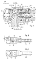
- den vorderen Endbereich eines Behandlungsinstruments in abgewandelter Ausgestaltung im axialen Schnitt;
- Fig. 6
- einen Handstückschaft des Behandlungsinstruments nach Fig. 5 in der Draufsicht;
- Fig. 7
- die in Fig. 1 mit Y gekennzeichnete Einzelheit, nämlich eine Haltevorrichtung für ein Behandlungs-Werkzeug im vorderen Endbereich des Behandlungsinstruments im axialen Schnitt in abgewandelter Ausgestaltung;
- Fig. 8
- das vordere Ende eines Handstückschaftes der Haltevorrichtung nach Fig. 7 in teilweise abgwandelter Ausgestaltung im axialen Schnitt;
- Fig. 9
- den Handstückschaft nach Fig. 8 in der Draufsicht;
- Fig. 10
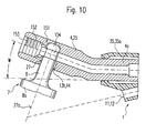
- die in Fig. 1 mit Y gekennzeichnete Einzelheit, nämlich eine im vorderen Endbereich des Behandlungsinstruments angeordnete Haltevorrichtung für ein Werkzeug im axialen Schnitt in weiter abgewandelter Ausgestaltung;
- Fig. 11
- eine der Fig. 10 entsprechende Ansicht in weiter abgewandelter Ausgestaltung;
- Fig. 12
- den Schnitt XII-XII in Fig. 11;
- Fig. 13
- einen Längsabschnitt eines erfindungsgemäßen Behandlungsinstruments in abgewandelter Ausgestaltung im axialen Schnitt;
- Fig. 14
- den Längsabschnitt nach Fig. 13 in der Draufsicht.
Claims (34)
- Medizinisches oder dentalmedizinisches Behandlungsinstrument (1) zur spanabhebenden Bearbeitung von Körpergewebe oder einem Ersatzstoff mit einem abrasiven Werkzeug (7), bestehend aus einem Handstück (2) in dessen vorderem Endbereich ein das Werkzeug (7) tragendes Schwingteil (4) gelagert ist, das durch einen Schwingungserreger (5) in Schwingungen versetzbar ist, wobei das Handstück (2) an seinem hinteren Endbereich mit einer flexiblen Versorgungsleitung (18) verbunden oder verbindbar ist, die sich von einer Versorgungseinrichtung erstreckt,
dadurch gekennzeichnet,
daß die Leistung des Schwingungserregers (5) veränderlich ist und eine Steuervorrichtung (72) vorgesehen ist, mit der die Leistung vergrößerbar oder verringerbar ist. - Medizinisches oder dentalmedizinisches Behandlungsinstrument nach Anspruch 1,
dadurch gekennzeichnet,
daß eine Einstellvorrichtung (73) mit einem manuell verstellbaren Einstellglied (74) vorgesehen ist, die auf die Steuervorrichtung (72) einwirkt oder die Steuervorrichtung (72) bildet. - Medizinisches oder dentalmedizinisches Behandlungsinstrument nach Anspruch 1 oder 2,
dadurch gekennzeichnet,
daß der Schwingungserreger (5) durch Druckluft antreibbar bzw. erregbar ist und die Steuervorrichtung (72) durch ein Steuerventil (65) gebildet ist, dessen Ventilschieber (66) die Größe einer Ventilöffnung (67) steuert, die in einer sich zum Schwingungserreger (5) erstreckenden Zuführungsleitung (15b) für Druckluft angeordnet ist. - Medizinisches oder dentalmedizinisches Behandlungsinstrument nach Anspruch 3,
dadurch gekennzeichnet,
daß das Steuerventil (65) einen Ventilschieber (66) aufweist, der vorzugsweise axial bewegbar gelagert und durch den am Schwingungserreger (5) anstehenden Druck (p1) gegen die Kraft einer Feder (65) beaufschlagt ist und eine Steuerkante (88) zum Steuern der Größe der Ventilöffnung (67) aufweist. - Medizinisches oder dentalmedizinisches Behandlungsinstrument (1) zur spanabhebenden Bearbeitung von Körpergewebe oder einem Ersatzstoff mit einem abrasiven Werkzeug (7), bestehend aus einem Handstück (2), in dessen vorderem Endbereich ein das Werkzeug (7) tragendes Schwingteil (4) gelagert ist, das durch einen Schwingungserreger (5) in Schwingungen versetzbar ist, wobei das Handstück (2) an seinem hinteren Endbereich mit einer flexiblen Versorgungsleitung (18) verbunden oder verbindbar ist, die sich von einer Versorgungseinrichtung erstreckt, wobei der Schwingungserreger (5) durch Druckluft antreibbar bzw. erregbar ist, die durch eine Zuführungsleitung (15b) zuführbar ist, oder Behandlungsinstrument nach einem der vorherigen Ansprüche,
dadurch gekennzeichnet,
daß in der Zuführungsleitung (15b) ein Druckregler (71) vorgesehen ist, der auch beim Vorhandensein unterschiedlich hoher Beiriebsdrücke (p2) einen im wesentlichen konstanten, am Schwingungserreger (5) anstehenden Arbeitsdruck (p1) regelt. - Medizinisches oder dentalmedizinisches Behandlungsinstrument (1) nach Anspruch 5,
dadurch gekennzeichnet,
daß ein Druckregelventil (71a) mit einem Ventilschieber (66) vorgesehen ist, der vom Arbeitsdruck (p1) gegen die Kraft einer Feder (68) vorzugsweise axial verstellbar gelagert ist, und bei größerem Betriebsdruck (p2) eine kleinere Ventilöffnung (67) und bei kleinerem Betriebsdruck (p2) eine größere Ventilöffnung (67) steuert. - Medizinisches oder dentalmedizinisches Behandlungsinstrument nach einem der vorherigen Ansprüche,
dadurch gekennzeichnet,
daß die Steuervorrichtung (72) und der Druckregler (71) vorgesehen sind. - Medizinisches oder dentalmedizinisches Behandlungsinstrument (1) nach Anspruch 7,
dadurch gekennzeichnet,
däß die Steuervorrichtung (72) auf den Druckregler (71), oder auf den Ventilschieber (66) einwirkt. - Medizinisches oder dentalmedizinisches Behandlungsinstrument (1) nach Anspruch 8,
dadurch gekennzeichnet,
daß die Kraft der Ventilfeder (68) durch die Steuervorrichtung (72) veränderlich ist. - Medizinisches oder dentalmedizinisches Behandlungsinstrument nach einem der vorherigen Ansprüche 2 bis 9,
dadurch gekennzeichnet,
daß die Einstellvorrichtung (73) und/oder das Steuerventil (65) und/oder das Druckregelventil (71a) im Handstück (2) angeordnet ist bzw. sind. - Medizinisches oder dentalmedizinisches Behandlungsinstrument nach Anspruch 10,
dadurch gekennzeichnet,
daß das Einsteliglied (74) im hinteren Endbereich des Handstücks (2) angeordnet ist. - Medizinisches oder dentalmedizinisches Behandlungsinstrument nach einem der Ansprüche 2 bis 11,
dadurch gekennzeichnet,
daß das Einstellglied (74) an der Mantelfläche des Handstücks (2) angeordnet ist oder die Mantelfläche bildet und vorzugsweise in Umfangsrichtung verstellbar ist. - Medizinisches oder dentalmedizinisches Behandlungsinstrument nach Anspruch 12,
dadurch gekennzeichnet,
daß das Einstellglied (74) durch eine Hülse (74a) gebildet ist. - Medizinisches oder dentalmedizinisches Behandlungsinstrument nach einem der vorherigen Ansprüche 2 bis 13,
dadurch gekennzeichnet,
daß die Einstellvorrichtung (73) ein im Handstück (2) beweglich gelagertes Verstellglied (81) aufweist, das durch ein Untersetzungsgetriebe mit dem Einstellglied (74) verbunden ist. - Medizinisches oder dentalmedizinisches Behandlungsinstrument nach einem der vorherigen Ansprüche 2 bis 14,
dadurch gekennzeichnet,
daß die Einstellvorrichtung (73) ein im Handstück (2) beweglich, vorzugsweise axial beweglich, gelagertes Verstellglied (81) aufweist, das durch einen Mechanismus mit dem Einstellglied (74) verbunden ist, der die Bewegungsrichtung des Verstellgliedes (81) bezüglich der des Einstellgliedes (74) verändert. - Medizinisches oder dentalmedizinisches Behandlungsinstrument nach einem der vorherigen Ansprüche,
dadurch gekennzeichnet,
daß vom Einstellglied (74) ein Steg (76) radial nach innen durch einen Schlitz (77a) der Griffhülse (41) ragt, der eine Schräg- oder Kurvenfläche (79) aufweist, vorzugsweise an seiner Rückseite oder Vorderseite. - Medizinisches oder dentalmedizinisches Behandlungsinstrument nach einem der vorherigen Ansprüche 2 bis 16,
dadurch gekennzeichnet,
daß das Einstellglied (74a) mit einem Verstellglied (81) verbunden ist, das ein Widerlager für die Feder (68) des Steuerventils (65) bildet. - Medizinisches oder dentalmedizinisches Behandlungsinstrument nach einem der Ansprüche 2 bis 17,
dadurch gekennzeichnet,
daß der Einstellvorrichtung (73) eine manuell überdrückbare Feststellvorrichtung (83) oder Verrastungsvorrichtung (84) zum Sichern in der jeweils eingestellten Position zugeordnet ist. - Medizinisches oder denialmedizinisches Behandlungsinstrument (1) zur spanabhebenden Bearbeitung von Körpergewebe oder einem Ersatzstoff mit einem abrasiven Werkzeug (7), bestehend aus einem Handstück (2), in dessen vorderem Endbereich ein das Werkzeug (7) tragendes Schwingteil (4) gelagert ist, das durch einen Schwingungserreger (5) in Schwingungen versetzbar ist, wobei das Handstück (2) an seinem hinteren Endbereich mit einer flexiblen Versorgungsleitung (18) verbunden oder verbindbar ist, die sich von einer Versorgungseinrichtung erstreckt, oder Behandlungsinstrument (1) nach einer der vorherigen Ansprüche,
dadurch gekennzeichnet,
daß der Schwingungserreger (5) von einem zusätzlichen Innengehäuse (43) umgeben ist. - Medizinisches oder dentalmedizinisches Behandlungsinstrument nach Anspruch 19,
dadurch gekennzeichnet,
daß der Schwingungserreger (5) pneumatisch antreibbar ist und ein stabförmiges, sich axial oder axparallel erstreckendes Schwingteil (4) aufweist, das im Bereich von radialen Druckluft-Austrittslöchern (63) mit radialem Abstand von einer Schwinghülse (64) umgeben ist, daß zwischen dem Innengehäuse (43) und einem Außengehäuse (41) ein radialer Abstand vorgesehen ist, daß zwischen dem Innengehäuse (43) und der Schwinghülse (64) ein deren Schwingungen gewährleistender radialer Abstand vorgesehen ist und daß das Innengehäuse (43) einen Luftaustritt aufweist. - Medizinisches oder dentalmedizinisches Behandlungsinstrument nach Anspruch 9 oder 20,
dadurch gekennzeichnet,
daß das Innenghäuse durch eine Hülse (43) gebildet ist, zwischen deren hinterem und/oder vorderem Endbereich und dem Schwingteil (4a) ein axial vorzugsweise formschlüssig gesicherter Stützring (42,43b) aus elastisch verformbaren Material angeordnet ist. - Medizinisches oder dentalmedizinisches Behandlungsinstrument nach Anspruch 21,
dadurch gekennzeichnet,
daß vorzugsweise der vordere Stützring (43b) luftdurchlässig ist. - Medizinisches oder dentalmedizinisches Behandlungsinstrument nach Anspruch 21 oder 22,
dadurch gekennzeichnet,
daß der hintere oder vordere Stützring (43b) aus Gummi, Kunststoff oder Filz besteht. - Medizinisches oder dentalmedizinisches Behandlungsinstrument nach einem der Ansprüche 19 bis 23,
dadurch gekennzeichnet,
daß das Innengehäuse (43) an seinem vorzugsweise hinteren Ende mit einem Lagerring (45) insbesondere muffenförmig verbunden ist, vorzugsweise aufgesteckt ist. - Medizinisches oder dentalmedizinisches Behandlungsinstrument (1) zur spanabhebenden Bearbeitung von Körpergewebe oder einem Ersatzstoff mit einem abrasiven Werkzeug (7), bestehend aus einem Handstück (2), in dessen vorderem Endbereich ein das Werkzeug (7) tragendes Schwingteil (4) gelagert ist, das durch einen Schwingungserreger (5) in Schwingungen versetzbar ist, wobei das Handstück (2) an seinem hinteren Endbereich mit einer flexiblen Versorgungsleitung (18) verbunden oder verbindbar ist, die sich von einer Versorgungseinrichtung erstreckt, oder Behandlungsinstrument nach einem der vorherigen Ansprüche,
dadurch gekennzeichnet,
daß auf dem vorragenden Handstückschaft (25) ein Schutzmantel (35a) aus elastisch nachgiebigem Material angeordnet ist. - Medizinisches oder dentalmedizinisches Behandlungsinstrument nach Anspruch 25,
dadurch gekennzeichnet,
daß der Schutzmantel (35a) in seinem hinteren Endbereich mit einem Gehäuse (41) oder einer Frontkappe (39) verbunden ist, vorzugsweise axial formschlüssig fixiert ist. - Medizinisches oder dentalmedizinisches Behandlungsinstrument (1) zur spanabhebenden Bearbeitung von Körpergewebe oder einem Ersatzstoff mit einem abrasiven Werkzeug (7), bestehend aus einem Handstück (2), in dessen vorderem Endbereich ein das Werkzeug (7) tragendes Schwingteil (4) gelagert ist, das durch einen Schwingungserreger (5) in Schwingungen versetzbar ist, wobei das Handstück (2) an seinem hinteren Endbereich mit einer flexiblen Versorgungsleitung (18) verbunden oder verbindbar ist, die sich von einer Versorgungseinrichtung erstreckt, oder Behandlungsinstrument nach einem der vorherigen Ansprüche,
dadurch gekennzeichnet,
daß der Lichtleiter (9) sich durch den Lagerring (35) in einer ihn aufnehmenden Ausnehmung oder in einem Kanal (11a) erstreckt. - Medizinisches oder dentalmedizinisches Behandlungsinstrument nach Anspruch 27,
dadurch gekennzeichnet,
daß das Schwingteil (4) zur dem Werkzeug (7) abgewandten Seite hin exzentrisch in der Griffhülse (41) gelagert ist und der Lagerring (35) exzentrisch ist. - Medizinisches oder dentalmedizinisches Behandlungsinstrument nach einem der vorherigen Ansprüche 27 oder 28,
dadurch gekennzeichnet,
daß der Lagerring (35) das vordere Ende des Handstücks (41) in Form einer Hülse überragt. - Medizinisches oder dentalmedizinisches Behandlungsinstrument nach einem der vorherigen Ansprüche 27 bis 29,
dadurch gekennzeichnet,
daß der Lagerring (35) in einer Frontkappe (39) der Griffhülse (41) gelagert ist und vorzugsweise darin axial formschlüssig fixiert ist. - Behandlungsinstrument nach einem der vorherigen Ansprüche 2 bis 30,
dadurch gekennzeichnet,
daß auf dem Verstellweg des Einstellglieds (74) eine Markierung (155) und/oder Skalierung jeweils mit einer Gegenmarkierung oder mit einer Gegenskalierung bzw. einem Index und/oder eine oder mehrere Raststellen (166) am Einstellglied (74) und einem ihm benachbarten Teil, insbesondere dem das Einstellglied (74) tragenden Teil, angeordnet ist bzw. sind. - Behandlungsinstrument nach Anspruch 31,
dadurch gekennzeichnet,
däß die Markierung (155) unterschiedliche Zeichen oder Farben aufweist. - Behandlungsinstrument nach Anspruch 31 oder 32,
dadurch gekennzeichnet,
daß mehrere unterschiedliche Werkzeuge (7) vorgesehen sind, die sich z.B. bezüglich ihrer Form und/oder Größe und/oder Festigkeit und/oder Abtragsfähigkeit voneinander unterscheiden. - Behandlungsinstrument nach Anspruch 33,
dadurch gekennzeichnet,
daß die Werkzeuge (7) vorzugsweise jeweils am Werkzeugschaft (8) eine Markierung (156) aufweisen, wobei die Position der Markierung (155) und/oder der Raststellen (166) auf dem Verstellweg einem bestimmten spezifischen Unterscheidungsmerkmal des zugehörigen Werkzeugs (7) entspricht.
Priority Applications (1)
| Application Number | Priority Date | Filing Date | Title |
|---|---|---|---|
| EP03001043A EP1302174B1 (de) | 1997-04-18 | 1998-04-16 | Medizinisches oder dentalmedizinisches Behandlungsinstrument zur spanabhebenden Bearbeitung von Körpergewebe oder einem Ersatzstoff mit einem abrasiven Werkzeug |
Applications Claiming Priority (6)
| Application Number | Priority Date | Filing Date | Title |
|---|---|---|---|
| DE19716416 | 1997-04-18 | ||
| DE19716416 | 1997-04-18 | ||
| DE19745245A DE19745245A1 (de) | 1997-04-18 | 1997-10-13 | Handstück für medizinische Zwecke insbesondere für eine ärztliche oder zahnärztliche Behandlungseinrichtung, vorzugsweise für eine spanabhebende Bearbeitung eines Zahn-Wurzelkanals |
| DE19745245 | 1997-10-13 | ||
| DE19751584 | 1997-11-21 | ||
| DE19751584A DE19751584A1 (de) | 1997-04-18 | 1997-11-21 | Medizinisches oder dentalmedizinisches Behandlungsinstrument zur spanabhebenden Bearbeitung von Körpergewebe oder einem Ersatzstoff mit einem abrasiven Werkzeug |
Related Child Applications (1)
| Application Number | Title | Priority Date | Filing Date |
|---|---|---|---|
| EP03001043A Division EP1302174B1 (de) | 1997-04-18 | 1998-04-16 | Medizinisches oder dentalmedizinisches Behandlungsinstrument zur spanabhebenden Bearbeitung von Körpergewebe oder einem Ersatzstoff mit einem abrasiven Werkzeug |
Publications (3)
| Publication Number | Publication Date |
|---|---|
| EP0872217A1 true EP0872217A1 (de) | 1998-10-21 |
| EP0872217B1 EP0872217B1 (de) | 2003-04-02 |
| EP0872217B2 EP0872217B2 (de) | 2006-12-27 |
Family
ID=27217317
Family Applications (1)
| Application Number | Title | Priority Date | Filing Date |
|---|---|---|---|
| EP98106881A Expired - Lifetime EP0872217B2 (de) | 1997-04-18 | 1998-04-16 | Medizinisches oder dentalmedizinisches Behandlungsinstrument zur spanabhebenden Bearbeitung von Körpergewebe oder einem Ersatzstoff mit einem abrasiven Werkzeug |
Country Status (5)
| Country | Link |
|---|---|
| US (1) | US6176703B1 (de) |
| EP (1) | EP0872217B2 (de) |
| JP (1) | JPH10295703A (de) |
| AT (2) | ATE235858T1 (de) |
| DE (1) | DE59813706D1 (de) |
Families Citing this family (16)
| Publication number | Priority date | Publication date | Assignee | Title |
|---|---|---|---|---|
| FR2799114B1 (fr) * | 1999-09-30 | 2001-11-09 | Anthogyr Sa | Piece a main dentaire comportant des moyens mecaniques de limitation de couple |
| DE10030114A1 (de) | 2000-06-19 | 2001-12-20 | Kaltenbach & Voigt | Handstück für medizinische Zwecke, insbesondere für eine ärztliche oder zahnärztliche Behandlungseinrichtung, vorzugsweise für eine spanabhebende Bearbeitung eines Zahn-Wurzelkanals |
| DE10039198B4 (de) * | 2000-08-10 | 2015-03-19 | Kaltenbach & Voigt Gmbh | Medizinisches oder dentalmedizinisches Behandlungsinstrument mit einem insbesondere pneumatischen Schwingantrieb |
| DE20013827U1 (de) * | 2000-08-10 | 2001-12-20 | Kaltenbach & Voigt GmbH & Co., 88400 Biberach | Medizinisches oder dentalmedizinisches Behandlungsinstrument mit einem Werkzeugträger in Form eines Schwingstabes |
| DE10238556A1 (de) * | 2002-08-22 | 2004-03-04 | Kaltenbach & Voigt Gmbh & Co. Kg | Ärztliches oder zahnärztliches stabförmiges Handstück mit einem Display |
| FR2846871B1 (fr) * | 2002-11-08 | 2005-01-21 | Micro Mega Int Mfg Sa | Instrument de traitement parodontal. |
| WO2007047983A2 (en) * | 2005-10-20 | 2007-04-26 | Graham John W | Method and system for temporary skeletal anchorage in orthodontics |
| US20070149881A1 (en) * | 2005-12-22 | 2007-06-28 | Rabin Barry H | Ultrasonically Powered Medical Devices and Systems, and Methods and Uses Thereof |
| US20100015329A1 (en) * | 2008-07-16 | 2010-01-21 | National Semiconductor Corporation | Methods and systems for packaging integrated circuits with thin metal contacts |
| JP5194240B2 (ja) * | 2008-08-26 | 2013-05-08 | 株式会社ミクロン | 歯科用ハンドピースの流量制御機構 |
| US8716676B2 (en) * | 2011-08-04 | 2014-05-06 | Xei Scientific, Inc. | Device to load TEM sample holders into a vacuum chamber |
| US20180228572A1 (en) * | 2017-02-13 | 2018-08-16 | Pac-Dent International, Inc. | Dental handpiece with rear air exhaust |
| KR101955327B1 (ko) * | 2018-01-17 | 2019-06-24 | 주식회사 덴탈로이드 | 공기압 조절이 가능한 치과용 핸드피스 |
| US11517328B2 (en) | 2019-03-19 | 2022-12-06 | Arthrex, Inc. | Force absorption system for disposable shavers and burrs |
| CN113303864B (zh) * | 2020-06-30 | 2023-03-14 | 重庆西山科技股份有限公司 | 刀头角度可调的弯管磨削刀具 |
| CN112472224A (zh) * | 2020-12-21 | 2021-03-12 | 上海圣哲医疗科技有限公司 | 一种超声手术刀的刀杆组件 |
Citations (6)
| Publication number | Priority date | Publication date | Assignee | Title |
|---|---|---|---|---|
| FR2132434A1 (de) * | 1971-03-31 | 1972-11-17 | Goof Sven Karl Lennart | |
| FR2505172A1 (fr) * | 1981-05-06 | 1982-11-12 | Micro Mega Sa | Detartreur pneumatique a vibration sub-sonique |
| US4484893A (en) * | 1983-02-22 | 1984-11-27 | Taco Products, Inc. | Air turbine handpiece for dental scaling and other applications |
| FR2550439A1 (fr) * | 1983-08-08 | 1985-02-15 | Kaltenbach & Voigt | Piece a main pour enlever le tartre dentaire |
| FR2613090A1 (fr) * | 1987-03-27 | 1988-09-30 | Micro Mega Sa | Dispositif de reglage d'un debit gazeux |
| WO1996014024A1 (de) | 1994-11-04 | 1996-05-17 | Kaltenbach & Voigt Gmbh & Co. | System zur beseitigung eines defektes an einem zahn und einsatzteil oder werkzeug für ein solches system |
Family Cites Families (8)
| Publication number | Priority date | Publication date | Assignee | Title |
|---|---|---|---|---|
| US3645255A (en) * | 1970-02-02 | 1972-02-29 | Hydrosonic Corp | Ultrasonic tooth-cleaning apparatus |
| DE2730137A1 (de) * | 1977-07-04 | 1979-01-25 | Kaltenbach & Voigt | Zahnaerztliches turbinenhandstueck |
| US4453919A (en) * | 1981-04-24 | 1984-06-12 | Micron Co., Ltd. | Dental scaler |
| US4427384A (en) * | 1982-07-22 | 1984-01-24 | Sertich Anthony T | Vibratory dental scaler |
| DE3328605C2 (de) * | 1983-08-08 | 1987-03-05 | Kaltenbach & Voigt Gmbh & Co, 7950 Biberach | Handstück zur Zahnsteinentfernung |
| US5190456A (en) * | 1986-09-26 | 1993-03-02 | Micron Co., Ltd. | Air-driven dental scaler |
| US5232363A (en) * | 1991-06-11 | 1993-08-03 | Eran Meller | Scaler with improved vibration characteristics |
| US5496172A (en) * | 1994-08-10 | 1996-03-05 | Albelda; David | Pneumatic remover for use in removing dental prosthetics |
-
1998
- 1998-03-30 US US09/050,119 patent/US6176703B1/en not_active Expired - Lifetime
- 1998-04-16 EP EP98106881A patent/EP0872217B2/de not_active Expired - Lifetime
- 1998-04-16 DE DE59813706T patent/DE59813706D1/de not_active Expired - Lifetime
- 1998-04-16 AT AT98106881T patent/ATE235858T1/de active
- 1998-04-16 AT AT03001043T patent/ATE337744T1/de active
- 1998-04-17 JP JP10108278A patent/JPH10295703A/ja active Pending
Patent Citations (7)
| Publication number | Priority date | Publication date | Assignee | Title |
|---|---|---|---|---|
| FR2132434A1 (de) * | 1971-03-31 | 1972-11-17 | Goof Sven Karl Lennart | |
| FR2505172A1 (fr) * | 1981-05-06 | 1982-11-12 | Micro Mega Sa | Detartreur pneumatique a vibration sub-sonique |
| US4484893A (en) * | 1983-02-22 | 1984-11-27 | Taco Products, Inc. | Air turbine handpiece for dental scaling and other applications |
| FR2550439A1 (fr) * | 1983-08-08 | 1985-02-15 | Kaltenbach & Voigt | Piece a main pour enlever le tartre dentaire |
| AT379505B (de) | 1983-08-08 | 1986-01-27 | Kaltenbach & Voigt | Zahnsteinentfernungs-handstueck |
| FR2613090A1 (fr) * | 1987-03-27 | 1988-09-30 | Micro Mega Sa | Dispositif de reglage d'un debit gazeux |
| WO1996014024A1 (de) | 1994-11-04 | 1996-05-17 | Kaltenbach & Voigt Gmbh & Co. | System zur beseitigung eines defektes an einem zahn und einsatzteil oder werkzeug für ein solches system |
Also Published As
| Publication number | Publication date |
|---|---|
| EP0872217B2 (de) | 2006-12-27 |
| US6176703B1 (en) | 2001-01-23 |
| DE59813706D1 (de) | 2006-10-12 |
| ATE235858T1 (de) | 2003-04-15 |
| JPH10295703A (ja) | 1998-11-10 |
| ATE337744T1 (de) | 2006-09-15 |
| EP0872217B1 (de) | 2003-04-02 |
Similar Documents
| Publication | Publication Date | Title |
|---|---|---|
| EP0919205A2 (de) | Medizinisches oder dentalmedizinisches Behandlungsinstrument zur spanabhebenden Behandlung von Körpergewebe oder einem Ersatzstoff | |
| EP0827719B1 (de) | Medizinisches oder zahnmedizinisches Laserinstrument, insbesondere für Zahn-Wurzelkanalbehandlungen | |
| DE69629895T2 (de) | Schlüsselloser Spannfutter für chirurgisches Blatt | |
| EP1129812B1 (de) | Laserinstrument | |
| EP0872217B1 (de) | Medizinisches oder dentalmedizinisches Behandlungsinstrument zur spanabhebenden Bearbeitung von Körpergewebe oder einem Ersatzstoff mit einem abrasiven Werkzeug | |
| AT409820B (de) | Medizinisches oder dentalmedizinisches behandlungsinstrument mit einem werkzeugträger in form eines schwingstabes | |
| AT409821B (de) | Medizinisches oder dentalmedizinisches behandlungsinstrument mit einem insbesondere pneumatischen schwingantrieb | |
| CH663533A5 (de) | Zahnsteinentfernungs-handstueck. | |
| DE2558064B2 (de) | Zahnärztliches Handstück | |
| EP0873724A1 (de) | Handstück für medizinische Zwecke, insbesondere für eine ärztliche oder zahnärztliche Behandlungseinrichtung, vorzugsweise für eine spanabhebende Bearbeitung eines Zahn-Wurzelkanals | |
| EP0642770A2 (de) | Winkelförmiges oder gerades Handstück mit einer lösbaren Spannvorrichtung für ein Werkzeug, insbesondere für medizinische Zwecke | |
| DE4417810A1 (de) | Ärztliches oder zahnärztliches Handstück | |
| EP1159928B1 (de) | Medizinisches Handstück mit einem stabförmigen Griffteil | |
| EP1216009A1 (de) | Durch eine schraubverbindung zu verbindende teile, insbesondere eines medizinischen instrumentes | |
| EP0898941A1 (de) | Medizinisches oder dentalmedizinisches Handstück mit einem Werkzeug zur spanabhebenden Bearbeitung | |
| EP2781201B1 (de) | Filterpatrone für eine medizinische, insbesondere dentale, Kupplungsvorrichtung | |
| EP2422738B1 (de) | Schall- und Ultraschalldentalinstrument, Schallspitzenkupplungsvorrichtung und Schallspitzenwerkzeug | |
| EP1302174B1 (de) | Medizinisches oder dentalmedizinisches Behandlungsinstrument zur spanabhebenden Bearbeitung von Körpergewebe oder einem Ersatzstoff mit einem abrasiven Werkzeug | |
| EP1574170A1 (de) | Justierbares Bearbeitungshilfsmittel für die Knochenbearbeitung | |
| EP2029041A1 (de) | Handstück für insbesondere medizinische laseranwendungen | |
| DE3310667C2 (de) | Schaltventil, insbesondere Druckluft-Einlaßventil | |
| AT405365B (de) | Handstück für ein lasergerät und kupplungsstück für ein handstück eines lasergerätes | |
| AT411567B (de) | Bohrer zur herstellung von bohrungen in einem knochengewebe | |
| DE102005009802A1 (de) | Medizinisches Werkzeug oder Handstück zum Schneiden einer Hartmaterialwand und Verfahren zum Schneiden einer Materialwand unter Verwendung eines medizinischen Handstücks mit Werkzeug | |
| DE19751584A1 (de) | Medizinisches oder dentalmedizinisches Behandlungsinstrument zur spanabhebenden Bearbeitung von Körpergewebe oder einem Ersatzstoff mit einem abrasiven Werkzeug |
Legal Events
| Date | Code | Title | Description |
|---|---|---|---|
| PUAI | Public reference made under article 153(3) epc to a published international application that has entered the european phase |
Free format text: ORIGINAL CODE: 0009012 |
|
| AK | Designated contracting states |
Kind code of ref document: A1 Designated state(s): AT CH DE FR IT LI |
|
| AX | Request for extension of the european patent |
Free format text: AL;LT;LV;MK;RO;SI |
|
| 17P | Request for examination filed |
Effective date: 19981218 |
|
| AKX | Designation fees paid |
Free format text: AT CH DE FR IT LI |
|
| 17Q | First examination report despatched |
Effective date: 20010816 |
|
| GRAH | Despatch of communication of intention to grant a patent |
Free format text: ORIGINAL CODE: EPIDOS IGRA |
|
| GRAH | Despatch of communication of intention to grant a patent |
Free format text: ORIGINAL CODE: EPIDOS IGRA |
|
| GRAA | (expected) grant |
Free format text: ORIGINAL CODE: 0009210 |
|
| AK | Designated contracting states |
Designated state(s): AT CH DE FR IT LI |
|
| REG | Reference to a national code |
Ref country code: CH Ref legal event code: NV Representative=s name: A. BRAUN, BRAUN, HERITIER, ESCHMANN AG PATENTANWAE Ref country code: CH Ref legal event code: EP |
|
| REF | Corresponds to: |
Ref document number: 59807689 Country of ref document: DE Date of ref document: 20030508 Kind code of ref document: P |
|
| ET | Fr: translation filed | ||
| PLBQ | Unpublished change to opponent data |
Free format text: ORIGINAL CODE: EPIDOS OPPO |
|
| PLBI | Opposition filed |
Free format text: ORIGINAL CODE: 0009260 |
|
| PLAX | Notice of opposition and request to file observation + time limit sent |
Free format text: ORIGINAL CODE: EPIDOSNOBS2 |
|
| 26 | Opposition filed |
Opponent name: W&H DENTALWERK BUERMOOS GMBH Effective date: 20031229 |
|
| PLAB | Opposition data, opponent's data or that of the opponent's representative modified |
Free format text: ORIGINAL CODE: 0009299OPPO |
|
| PLBQ | Unpublished change to opponent data |
Free format text: ORIGINAL CODE: EPIDOS OPPO |
|
| PLBB | Reply of patent proprietor to notice(s) of opposition received |
Free format text: ORIGINAL CODE: EPIDOSNOBS3 |
|
| R26 | Opposition filed (corrected) |
Opponent name: W&H DENTALWERK BUERMOOS GMBH Effective date: 20031229 |
|
| PLAX | Notice of opposition and request to file observation + time limit sent |
Free format text: ORIGINAL CODE: EPIDOSNOBS2 |
|
| PUAH | Patent maintained in amended form |
Free format text: ORIGINAL CODE: 0009272 |
|
| STAA | Information on the status of an ep patent application or granted ep patent |
Free format text: STATUS: PATENT MAINTAINED AS AMENDED |
|
| 27A | Patent maintained in amended form |
Effective date: 20061227 |
|
| AK | Designated contracting states |
Kind code of ref document: B2 Designated state(s): AT CH DE FR IT LI |
|
| ET3 | Fr: translation filed ** decision concerning opposition | ||
| REG | Reference to a national code |
Ref country code: CH Ref legal event code: PFA Owner name: KALTENBACH & VOIGT GMBH & CO. Free format text: KALTENBACH & VOIGT GMBH & CO.#BISMARCKRING 39#88400 BIBERACH/RISS (DE) -TRANSFER TO- KALTENBACH & VOIGT GMBH & CO.#BISMARCKRING 39#88400 BIBERACH/RISS (DE) |
|
| PLAB | Opposition data, opponent's data or that of the opponent's representative modified |
Free format text: ORIGINAL CODE: 0009299OPPO |
|
| PGFP | Annual fee paid to national office [announced via postgrant information from national office to epo] |
Ref country code: IT Payment date: 20110421 Year of fee payment: 14 |
|
| PG25 | Lapsed in a contracting state [announced via postgrant information from national office to epo] |
Ref country code: IT Free format text: LAPSE BECAUSE OF NON-PAYMENT OF DUE FEES Effective date: 20120416 |
|
| REG | Reference to a national code |
Ref country code: CH Ref legal event code: PCAR Free format text: NEW ADDRESS: HOLBEINSTRASSE 36-38, 4051 BASEL (CH) |
|
| REG | Reference to a national code |
Ref country code: FR Ref legal event code: PLFP Year of fee payment: 18 |
|
| PGFP | Annual fee paid to national office [announced via postgrant information from national office to epo] |
Ref country code: DE Payment date: 20150506 Year of fee payment: 18 Ref country code: CH Payment date: 20150423 Year of fee payment: 18 |
|
| PGFP | Annual fee paid to national office [announced via postgrant information from national office to epo] |
Ref country code: FR Payment date: 20150424 Year of fee payment: 18 Ref country code: AT Payment date: 20150427 Year of fee payment: 18 |
|
| REG | Reference to a national code |
Ref country code: DE Ref legal event code: R119 Ref document number: 59807689 Country of ref document: DE |
|
| REG | Reference to a national code |
Ref country code: CH Ref legal event code: PL |
|
| REG | Reference to a national code |
Ref country code: AT Ref legal event code: MM01 Ref document number: 235858 Country of ref document: AT Kind code of ref document: T Effective date: 20160416 |
|
| REG | Reference to a national code |
Ref country code: FR Ref legal event code: ST Effective date: 20161230 |
|
| PG25 | Lapsed in a contracting state [announced via postgrant information from national office to epo] |
Ref country code: DE Free format text: LAPSE BECAUSE OF NON-PAYMENT OF DUE FEES Effective date: 20161101 Ref country code: FR Free format text: LAPSE BECAUSE OF NON-PAYMENT OF DUE FEES Effective date: 20160502 Ref country code: LI Free format text: LAPSE BECAUSE OF NON-PAYMENT OF DUE FEES Effective date: 20160430 Ref country code: CH Free format text: LAPSE BECAUSE OF NON-PAYMENT OF DUE FEES Effective date: 20160430 |
|
| PG25 | Lapsed in a contracting state [announced via postgrant information from national office to epo] |
Ref country code: AT Free format text: LAPSE BECAUSE OF NON-PAYMENT OF DUE FEES Effective date: 20160416 |