EP0872403A2 - Guidage pour crémaillère - Google Patents
Guidage pour crémaillère Download PDFInfo
- Publication number
- EP0872403A2 EP0872403A2 EP98107159A EP98107159A EP0872403A2 EP 0872403 A2 EP0872403 A2 EP 0872403A2 EP 98107159 A EP98107159 A EP 98107159A EP 98107159 A EP98107159 A EP 98107159A EP 0872403 A2 EP0872403 A2 EP 0872403A2
- Authority
- EP
- European Patent Office
- Prior art keywords
- rack guide
- rack
- cylindrical
- segments
- movement
- Prior art date
- Legal status (The legal status is an assumption and is not a legal conclusion. Google has not performed a legal analysis and makes no representation as to the accuracy of the status listed.)
- Withdrawn
Links
- 230000002093 peripheral effect Effects 0.000 claims abstract description 33
- 230000000295 complement effect Effects 0.000 claims abstract description 12
- 239000000463 material Substances 0.000 claims description 10
- 239000002991 molded plastic Substances 0.000 claims description 4
- 208000016261 weight loss Diseases 0.000 description 7
- 239000013585 weight reducing agent Substances 0.000 description 7
- 239000003351 stiffener Substances 0.000 description 5
- 230000004048 modification Effects 0.000 description 2
- 238000012986 modification Methods 0.000 description 2
- 239000004033 plastic Substances 0.000 description 2
- 239000004809 Teflon Substances 0.000 description 1
- 229920006362 Teflon® Polymers 0.000 description 1
- 239000011521 glass Substances 0.000 description 1
- 239000000203 mixture Substances 0.000 description 1
- 239000003607 modifier Substances 0.000 description 1
- 238000000465 moulding Methods 0.000 description 1
- 229920000728 polyester Polymers 0.000 description 1
- 239000012763 reinforcing filler Substances 0.000 description 1
Images


Classifications
-
- B—PERFORMING OPERATIONS; TRANSPORTING
- B62—LAND VEHICLES FOR TRAVELLING OTHERWISE THAN ON RAILS
- B62D—MOTOR VEHICLES; TRAILERS
- B62D3/00—Steering gears
- B62D3/02—Steering gears mechanical
- B62D3/12—Steering gears mechanical of rack-and-pinion type
- B62D3/123—Steering gears mechanical of rack-and-pinion type characterised by pressure yokes
-
- F—MECHANICAL ENGINEERING; LIGHTING; HEATING; WEAPONS; BLASTING
- F16—ENGINEERING ELEMENTS AND UNITS; GENERAL MEASURES FOR PRODUCING AND MAINTAINING EFFECTIVE FUNCTIONING OF MACHINES OR INSTALLATIONS; THERMAL INSULATION IN GENERAL
- F16H—GEARING
- F16H55/00—Elements with teeth or friction surfaces for conveying motion; Worms, pulleys or sheaves for gearing mechanisms
- F16H55/02—Toothed members; Worms
- F16H55/26—Racks
- F16H55/28—Special devices for taking up backlash
- F16H55/283—Special devices for taking up backlash using pressure yokes
-
- Y—GENERAL TAGGING OF NEW TECHNOLOGICAL DEVELOPMENTS; GENERAL TAGGING OF CROSS-SECTIONAL TECHNOLOGIES SPANNING OVER SEVERAL SECTIONS OF THE IPC; TECHNICAL SUBJECTS COVERED BY FORMER USPC CROSS-REFERENCE ART COLLECTIONS [XRACs] AND DIGESTS
- Y10—TECHNICAL SUBJECTS COVERED BY FORMER USPC
- Y10T—TECHNICAL SUBJECTS COVERED BY FORMER US CLASSIFICATION
- Y10T74/00—Machine element or mechanism
- Y10T74/19—Gearing
- Y10T74/19642—Directly cooperating gears
- Y10T74/1967—Rack and pinion
Definitions
- the present invention relates to a rack and pinion steering gear, and particularly relates to a rack guide for supporting a rack in engagement with a pinion in a rack and pinion steering gear.
- the present invention is a rack guide for transmitting a preloading force from a spring to a steering rack in a rack and pinion steering gear housing.
- the rack guide is a cylindrical structure with an outer peripheral wall surface and an end wall surface.
- the outer peripheral wall surface has a cylindrical contour which is complementary to a cylindrical inner surface of the housing.
- the end wall surface has a cylindrical contour which is complementary to a cylindrical surface of the rack.
- the cylindrical structure has a plurality of relatively movable parts including circumferentially separate segments. Each of the segments defines a respective segmental portion of the outer peripheral wall surface.
- the relatively movable parts of the cylindrical structure further include a flexible web which interconnects and supports an adjacent pair of segments for movement relative to each other.
- the apparatus 10 is a rack and pinion steering gear including a housing 12 containing a rack 14 and a pinion 16.
- the rack 14 has a longitudinal central axis 17 and an axially extending row of rack teeth 18.
- the pinion 16 has an axis of rotation 19, and has helical gear teeth 20 meshing with the rack teeth 18.
- the opposite ends of the rack 14 are connected with a steering linkage and a corresponding pair of steerable vehicle wheels.
- the pinion 16 is connected with the vehicle steering wheel by an input shaft and a torsion bar. When a steering maneuver is being performed, the pinion 16 rotates about the axis 19, and the rack 14 moves longitudinally along the axis 17.
- the steering gear 10 further includes a rack guide 30.
- the rack guide 30 has a cylindrical shape centered on an axis 31 which is perpendicular to the rack axis 17. As shown in Fig. 1, the rack guide 30 is contained in a cylindrical section 32 of the housing 12 between a closure cap 34 and the rack 14.
- a spring 36 is compressed between the rack guide 30 and the closure cap 34.
- the spring 36 applies an axially directed preloading force which urges the rack guide 30 forcefully against the rack 14 in a direction extending from left to right, as viewed in Fig. 1.
- the rack guide 30, applies the preloading force to the rack 14 so as to hold the rack teeth 18 firmly in meshing engagement with the gear teeth 20 on the pinion 16.
- the rack guide 30 has an outer peripheral surface 40 with a cylindrical contour centered on the axis 31.
- the outer peripheral surface 40 is defined by a cylindrical peripheral wall 42 of the rack guide 30.
- the cylindrical contour of the outer surface 40 is complementary to a cylindrical inner surface 44 of the surrounding housing section 32.
- a first end portion 46 of the rack guide 30 includes a pair of diametrically opposed end segments 48 and 50 of the peripheral wall 42.
- the first end portion 46 of the rack guide 30 further includes a concave end wall 52 with a guide surface 54 extending across the axis 31.
- the guide surface 54 has a cylindrical contour which is complementary to a cylindrical surface portion 56 (Fig. 1) of the rack 14 opposite the rack teeth 18. When the rack 14 moves longitudinally along the axis 17, it slides against the guide surface 54.
- a second, opposite end portion 60 of the rack guide 30 defines a compartment 62 for receiving the spring 36.
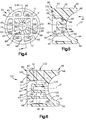
- the spring compartment 62 also is centered on the axis 31, and has a rectangular peripheral shape defined by an inner peripheral wall surface 63.
- the inner peripheral wall surface 63 is defined by a rectangular inner wall structure 64.
- the rectangular inner wall structure 64 is preferably square, as best shown in Fig. 4, and thus includes four orthogonal inner walls 71, 72, 73, and 74 with equal lengths extending around the axis 31.
- a cylindrical stub shaft portion 80 (Fig. 5) of the rack guide 30 extends partially along the axis 31 from the concave end wall 52 toward the open end of the spring compartment 62.
- the stub shaft 80 helps to center the spring 36 in the spring compartment 62, and is preferably hollow for weight reduction.
- a plurality of ribs 86 project radially from the stub shaft 80 to the four surrounding inner walls 71-74.
- the ribs 86 have coplanar spring-abutment surfaces 88 facing axially outward through the spring compartment 62.
- the rectangular inner wall structure 64 is joined with the cylindrical peripheral wall 42 at a plurality of locations. These include the four corners of the rectangular inner wall structure 64. More specifically, four corner junctures 91, 92, 93, and 94 extend radially outward from the four corners of the rectangular inner wall structure 64 to the cylindrical peripheral wall 42. A pair of stiffener walls 96 and 98 extend radially outward from the first and second inner walls 71 and 73 to the cylindrical peripheral wall 42. The stiffener walls 96 and 98 are perpendicular to the first and second inner walls 71 and 73 and intersect the cylindrical peripheral wall 42 at diametrically opposed locations. In this configuration, the rack guide 30 has a plurality of weight-reduction cavities 100.
- the weight reduction cavities 100 are located radially between the rectangular inner wall structure 64 and the cylindrical peripheral wall 42, and are located circumferentially between adjacent pairs of the corner junctures 91-94 and the stiffener walls 96 and 98. Like the spring compartment 62, the weight-reduction cavities 100 have depths extending axially from their open ends to the concave end wall 52 at the opposite end portion 46 of the rack guide 30.
- the rack guide 30 in the preferred embodiment of the present invention is a unitary structure consisting of a single continuous body of molded plastic material.
- the plastic material including any reinforcing filler materials, may have any suitable composition known in the art.
- a particularly suitable plastic material is a glass-filled polyester such as Rynite 545 or similar material with optional modifiers such as Teflon.
- the rectangular inner wall structure 64, the corner junctures 91-94, and the stiffener walls 96 and 98, together with the weight-reduction cavities 100 provide high structural rigidity with a low amount of material, i.e., a high performance to weight ratio. The use of less material enables faster molding cycle times with less shrinkage.
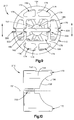
- Fig. 6 is a sectional view similar to Fig. 5 showing a rack guide 120 comprising a second embodiment of the present invention.
- the rack guide 120 has parts that are substantially similar to corresponding parts of the rack guide 30 described above. This is indicated by the use of the same reference numbers for such parts of the two different rack guides 120 and 30.
- the rack guide 120 differs from the rack guide 30 in that the rack guide 120 is substantially longer than the rack guide 30.
- the rack guide 120 is thus constructed for use in a steering gear housing with a cylindrical section that likewise differs from the cylindrical section 32 of the housing 12.
- the increased length of the rack guide 120 is provided by a longitudinally extending section 122 having a length L, as shown in Fig. 6.
- the rack guide 120 thus has ribs 126 which are axially larger than the ribs 86 (Fig. 5) in the rack guide 30.
- the distance from the spring-abutment surfaces 128 to the open end of the spring compartment 130 is the same as the corresponding distance in the rack guide 30.
- This enables the rack guide 120 to be used with a spring the same size as the spring 36.
- the various connector portions and wall portions of the rack guide 120 that are located radially outward of the ribs 126 are equally longer than their counterparts in the rack guide 30.
- the depths of the spring compartment 62 and the weight-reduction cavities 100 in the rack guide 120 are likewise greater. Accordingly, the length of a rack guide constructed in accordance with the present invention can be increased without substantially changing the performance to weight-ratio of the rack guide.
Landscapes
- Engineering & Computer Science (AREA)
- Mechanical Engineering (AREA)
- General Engineering & Computer Science (AREA)
- Chemical & Material Sciences (AREA)
- Combustion & Propulsion (AREA)
- Transportation (AREA)
- Transmission Devices (AREA)
- Power Steering Mechanism (AREA)
Applications Claiming Priority (2)
| Application Number | Priority Date | Filing Date | Title |
|---|---|---|---|
| US844032 | 1997-04-18 | ||
| US08/844,032 US5937703A (en) | 1997-02-25 | 1997-04-18 | Rack guide |
Publications (2)
| Publication Number | Publication Date |
|---|---|
| EP0872403A2 true EP0872403A2 (fr) | 1998-10-21 |
| EP0872403A3 EP0872403A3 (fr) | 1998-11-11 |
Family
ID=25291614
Family Applications (1)
| Application Number | Title | Priority Date | Filing Date |
|---|---|---|---|
| EP98107159A Withdrawn EP0872403A3 (fr) | 1997-04-18 | 1998-04-20 | Guidage pour crémaillère |
Country Status (5)
| Country | Link |
|---|---|
| US (1) | US5937703A (fr) |
| EP (1) | EP0872403A3 (fr) |
| JP (1) | JP2960048B2 (fr) |
| KR (1) | KR100296057B1 (fr) |
| BR (1) | BR9801414A (fr) |
Cited By (3)
| Publication number | Priority date | Publication date | Assignee | Title |
|---|---|---|---|---|
| DE10222183A1 (de) * | 2002-05-18 | 2003-11-27 | Zf Lenksysteme Gmbh | Zahnstangenlenkgetriebe |
| KR20160112849A (ko) * | 2015-03-20 | 2016-09-28 | 현대자동차주식회사 | 파워 스티어링 시스템용 랙 서포트 장치 |
| DE102018222383A1 (de) | 2018-12-20 | 2020-06-25 | Robert Bosch Gmbh | Lenkgetriebe und Lenksystem für ein Kraftfahrzeug |
Families Citing this family (12)
| Publication number | Priority date | Publication date | Assignee | Title |
|---|---|---|---|---|
| US6390700B1 (en) * | 2000-07-11 | 2002-05-21 | Lexmark International, Inc | Absolute location low wear bearing for an imaging apparatus |
| US6591706B2 (en) | 2001-05-01 | 2003-07-15 | Trw Inc. | Rack and pinion steering gear with a unitized yoke assembly |
| JP4306531B2 (ja) * | 2004-04-30 | 2009-08-05 | 株式会社ジェイテクト | ラックピニオン式舵取装置におけるラックガイド基体の製造方法及びラックガイド |
| US20070163375A1 (en) * | 2006-01-16 | 2007-07-19 | Trw Automotive U.S. Llc | Rack yoke assembly for use in a rack and pinion steering apparatus |
| JP5126883B2 (ja) * | 2007-11-30 | 2013-01-23 | 大同メタル工業株式会社 | ラックピニオン式ステアリング装置の摺動受板及びラックガイド |
| WO2009097648A1 (fr) * | 2008-02-07 | 2009-08-13 | Bishop Innovation Limited | Etrier de direction |
| DE102008026874B4 (de) * | 2008-06-05 | 2019-02-21 | Trw Automotive Gmbh | Vorrichtung zum Andrücken einer Zahnstange |
| DE102012013964B4 (de) * | 2012-07-13 | 2021-04-15 | Zf Automotive Germany Gmbh | Vorrichtung zum Andrücken einer Zahnstange an ein Ritzel |
| JP5888433B2 (ja) | 2013-06-05 | 2016-03-22 | 日本精工株式会社 | ガイドブッシュ及びラックピニオン式ステアリングギヤユニット |
| DE102015113765B4 (de) * | 2015-08-19 | 2017-09-07 | Tedrive Steering Systems Gmbh | Zahnstangenlenkung |
| US10618544B2 (en) * | 2016-05-20 | 2020-04-14 | Steering Solutions Ip Holding Corporation | Radially preloaded rack bearing |
| US11198466B2 (en) * | 2017-11-03 | 2021-12-14 | Steering Solutions Ip Holding Corporation | Wedge adjuster plug |
Family Cites Families (12)
| Publication number | Priority date | Publication date | Assignee | Title |
|---|---|---|---|---|
| US3747429A (en) * | 1971-11-09 | 1973-07-24 | Trw Inc | Yoke support for rack and pinion gear |
| DE2928732C2 (de) * | 1979-07-17 | 1982-10-21 | Zahnradfabrik Friedrichshafen Ag, 7990 Friedrichshafen | Zahnstangenlenkgetriebe, insbesondere für Kraftfahrzeuge |
| JPS5945149U (ja) * | 1982-09-17 | 1984-03-26 | トヨタ自動車株式会社 | ツクアンドピニオン式ステアリングギヤ装置 |
| JPS59206258A (ja) * | 1983-05-06 | 1984-11-22 | Jidosha Kiki Co Ltd | ラツクピニオン型ステアリング装置 |
| JPS59216764A (ja) * | 1983-05-24 | 1984-12-06 | Toyota Motor Corp | ラックアンドピニオン式ステアリング装置 |
| JPS6125275U (ja) * | 1984-07-20 | 1986-02-14 | トヨタ自動車株式会社 | ラツク・ピニオン型かじ取り装置のラツク・ガイド |
| US4785685A (en) * | 1986-04-09 | 1988-11-22 | Toyota Jidosha Kabushiki Kaisha | Rack guide of synthetic resin for a rack and pinion type steering device |
| EP0249315B1 (fr) * | 1986-06-09 | 1990-10-31 | Trw Cam Gears Limited | Mécanisme de direction assistée de véhicule |
| JP2503354Y2 (ja) * | 1988-04-22 | 1996-06-26 | 光洋精工株式会社 | 舵取装置 |
| JPH0635858Y2 (ja) * | 1988-05-17 | 1994-09-21 | 光洋精工株式会社 | 舵取装置 |
| US5022279A (en) * | 1988-11-08 | 1991-06-11 | Koyo Seiko Co., Ltd. | Rack and pinion steering device |
| JP3366785B2 (ja) * | 1995-09-19 | 2003-01-14 | 光洋精工株式会社 | ラックの支持装置 |
-
1997
- 1997-04-18 US US08/844,032 patent/US5937703A/en not_active Expired - Fee Related
-
1998
- 1998-04-18 KR KR1019980013953A patent/KR100296057B1/ko not_active Expired - Fee Related
- 1998-04-20 JP JP10109544A patent/JP2960048B2/ja not_active Expired - Fee Related
- 1998-04-20 EP EP98107159A patent/EP0872403A3/fr not_active Withdrawn
- 1998-04-20 BR BR9801414-5A patent/BR9801414A/pt not_active IP Right Cessation
Cited By (4)
| Publication number | Priority date | Publication date | Assignee | Title |
|---|---|---|---|---|
| DE10222183A1 (de) * | 2002-05-18 | 2003-11-27 | Zf Lenksysteme Gmbh | Zahnstangenlenkgetriebe |
| WO2003097427A1 (fr) * | 2002-05-18 | 2003-11-27 | Zf Lenksysteme Gmbh | Direction a cremaillere |
| KR20160112849A (ko) * | 2015-03-20 | 2016-09-28 | 현대자동차주식회사 | 파워 스티어링 시스템용 랙 서포트 장치 |
| DE102018222383A1 (de) | 2018-12-20 | 2020-06-25 | Robert Bosch Gmbh | Lenkgetriebe und Lenksystem für ein Kraftfahrzeug |
Also Published As
| Publication number | Publication date |
|---|---|
| US5937703A (en) | 1999-08-17 |
| EP0872403A3 (fr) | 1998-11-11 |
| KR19980081533A (ko) | 1998-11-25 |
| JP2960048B2 (ja) | 1999-10-06 |
| BR9801414A (pt) | 2001-09-18 |
| JPH10315989A (ja) | 1998-12-02 |
| KR100296057B1 (ko) | 2001-10-25 |
Similar Documents
| Publication | Publication Date | Title |
|---|---|---|
| US5937703A (en) | Rack guide | |
| US6076417A (en) | Rack guide having linear inner walls for supporting a rack | |
| EP0860345A2 (fr) | Guidage pour crémaillère | |
| EP0931714A1 (fr) | Système de direction assistée électrique avec réducteur de vitesse | |
| CA2166802A1 (fr) | Aspirateur a direction amelioree | |
| JP2005326009A (ja) | ボールねじ駆動装置 | |
| JP2937987B2 (ja) | ステアリング装置 | |
| CN108974111A (zh) | 转向装置 | |
| CN107571910A (zh) | 齿条辅助型电动转向装置 | |
| US5996723A (en) | Cable-type steering device | |
| JP3393762B2 (ja) | 車載用回転コネクタ | |
| JPH01169123A (ja) | 継手装置 | |
| JP3779743B2 (ja) | 電動パワーステアリング装置 | |
| JP2004058980A (ja) | 車両用電動式パワーステアリング装置 | |
| JP2000355278A (ja) | ステアリング用ボールねじおよびこのステアリング用ボールねじを用いたパワーステアリング装置 | |
| JPS6033704B2 (ja) | 力伝達装装置 | |
| JP3966622B2 (ja) | ケーブル式ステアリング装置における操舵角検出装置 | |
| US20080224434A1 (en) | Center take-off rack-and-pinion steering apparatus | |
| KR101922406B1 (ko) | 전동식 조향 장치용 플렉서블 댐퍼 장치 | |
| KR970705425A (ko) | 구형상 바퀴를 갖는 롤러 스케이트 및 그의 제조방법(improved roller skate) | |
| JP7188134B2 (ja) | ステアリング装置 | |
| CA1094427A (fr) | Direction a pignon et cremaillere | |
| US5855142A (en) | Retainer for ball screw crossover tube | |
| JP2001315655A (ja) | 電動パワーステアリング装置 | |
| KR200287277Y1 (ko) | 파워스티어링기어의베어링어셈블리 |
Legal Events
| Date | Code | Title | Description |
|---|---|---|---|
| PUAI | Public reference made under article 153(3) epc to a published international application that has entered the european phase |
Free format text: ORIGINAL CODE: 0009012 |
|
| PUAL | Search report despatched |
Free format text: ORIGINAL CODE: 0009013 |
|
| AK | Designated contracting states |
Kind code of ref document: A2 Designated state(s): DE ES FR GB IT |
|
| AX | Request for extension of the european patent |
Free format text: AL;LT;LV;MK;RO;SI |
|
| AK | Designated contracting states |
Kind code of ref document: A3 Designated state(s): AT BE CH CY DE DK ES FI FR GB GR IE IT LI LU MC NL PT SE |
|
| AX | Request for extension of the european patent |
Free format text: AL;LT;LV;MK;RO;SI |
|
| 17P | Request for examination filed |
Effective date: 19990428 |
|
| AKX | Designation fees paid |
Free format text: DE ES FR GB IT |
|
| 17Q | First examination report despatched |
Effective date: 20010129 |
|
| STAA | Information on the status of an ep patent application or granted ep patent |
Free format text: STATUS: THE APPLICATION HAS BEEN WITHDRAWN |
|
| 18W | Application withdrawn |
Withdrawal date: 20011120 |