EP0872406B1 - Verfahren und Vorrichtung zur Dämpfungskontrolle einer elektrischen Servolenkung mit Besonderheiten bei Verlust des Fahrzeuggeschwindigkeitssignals - Google Patents
Verfahren und Vorrichtung zur Dämpfungskontrolle einer elektrischen Servolenkung mit Besonderheiten bei Verlust des Fahrzeuggeschwindigkeitssignals Download PDFInfo
- Publication number
- EP0872406B1 EP0872406B1 EP98105435A EP98105435A EP0872406B1 EP 0872406 B1 EP0872406 B1 EP 0872406B1 EP 98105435 A EP98105435 A EP 98105435A EP 98105435 A EP98105435 A EP 98105435A EP 0872406 B1 EP0872406 B1 EP 0872406B1
- Authority
- EP
- European Patent Office
- Prior art keywords
- vehicle speed
- signal
- motor
- damping
- value
- Prior art date
- Legal status (The legal status is an assumption and is not a legal conclusion. Google has not performed a legal analysis and makes no representation as to the accuracy of the status listed.)
- Expired - Lifetime
Links
- 238000013016 damping Methods 0.000 title claims description 79
- 238000000034 method Methods 0.000 title claims description 27
- 230000004044 response Effects 0.000 claims description 22
- 230000008569 process Effects 0.000 description 16
- 230000000979 retarding effect Effects 0.000 description 14
- 230000006870 function Effects 0.000 description 8
- 230000033001 locomotion Effects 0.000 description 7
- 230000000694 effects Effects 0.000 description 4
- 230000007423 decrease Effects 0.000 description 3
- 238000001514 detection method Methods 0.000 description 2
- 238000001914 filtration Methods 0.000 description 2
- 238000012886 linear function Methods 0.000 description 2
- 230000005355 Hall effect Effects 0.000 description 1
- 230000005856 abnormality Effects 0.000 description 1
- 230000004913 activation Effects 0.000 description 1
- 230000005540 biological transmission Effects 0.000 description 1
- 230000008859 change Effects 0.000 description 1
- 230000036461 convulsion Effects 0.000 description 1
- 230000001419 dependent effect Effects 0.000 description 1
- 238000010586 diagram Methods 0.000 description 1
- 238000002474 experimental method Methods 0.000 description 1
- 230000002401 inhibitory effect Effects 0.000 description 1
- 230000007257 malfunction Effects 0.000 description 1
- 238000005259 measurement Methods 0.000 description 1
- 238000012544 monitoring process Methods 0.000 description 1
- 238000012545 processing Methods 0.000 description 1
- 238000012546 transfer Methods 0.000 description 1
- 238000004804 winding Methods 0.000 description 1
Images

Classifications
-
- B—PERFORMING OPERATIONS; TRANSPORTING
- B62—LAND VEHICLES FOR TRAVELLING OTHERWISE THAN ON RAILS
- B62D—MOTOR VEHICLES; TRAILERS
- B62D5/00—Power-assisted or power-driven steering
- B62D5/04—Power-assisted or power-driven steering electrical, e.g. using an electric servo-motor connected to, or forming part of, the steering gear
- B62D5/0457—Power-assisted or power-driven steering electrical, e.g. using an electric servo-motor connected to, or forming part of, the steering gear characterised by control features of the drive means as such
- B62D5/046—Controlling the motor
- B62D5/0466—Controlling the motor for returning the steering wheel to neutral position
-
- B—PERFORMING OPERATIONS; TRANSPORTING
- B62—LAND VEHICLES FOR TRAVELLING OTHERWISE THAN ON RAILS
- B62D—MOTOR VEHICLES; TRAILERS
- B62D5/00—Power-assisted or power-driven steering
- B62D5/04—Power-assisted or power-driven steering electrical, e.g. using an electric servo-motor connected to, or forming part of, the steering gear
- B62D5/0457—Power-assisted or power-driven steering electrical, e.g. using an electric servo-motor connected to, or forming part of, the steering gear characterised by control features of the drive means as such
- B62D5/046—Controlling the motor
- B62D5/0463—Controlling the motor calculating assisting torque from the motor based on driver input
-
- B—PERFORMING OPERATIONS; TRANSPORTING
- B62—LAND VEHICLES FOR TRAVELLING OTHERWISE THAN ON RAILS
- B62D—MOTOR VEHICLES; TRAILERS
- B62D5/00—Power-assisted or power-driven steering
- B62D5/04—Power-assisted or power-driven steering electrical, e.g. using an electric servo-motor connected to, or forming part of, the steering gear
- B62D5/0457—Power-assisted or power-driven steering electrical, e.g. using an electric servo-motor connected to, or forming part of, the steering gear characterised by control features of the drive means as such
- B62D5/0481—Power-assisted or power-driven steering electrical, e.g. using an electric servo-motor connected to, or forming part of, the steering gear characterised by control features of the drive means as such monitoring the steering system, e.g. failures
- B62D5/049—Power-assisted or power-driven steering electrical, e.g. using an electric servo-motor connected to, or forming part of, the steering gear characterised by control features of the drive means as such monitoring the steering system, e.g. failures detecting sensor failures
Definitions
- the present invention is directed to an electric assist steering system and is particularly directed to a method and apparatus for detecting a vehicle speed signal loss in an electric assist steering system and for damping control of an electric assist steering system when a vehicle speed signal loss occurs.
- Electric power assist steering systems that utilize a rack and pinion gear set provide power assist by using an electric motor to either (i) apply rotary force to a steering input shaft connected to a pinion gear, or (ii) apply linear force to a steering member having the rack teeth thereon.
- the electric motor in such systems is typically controlled in response to (i) a driver's applied steering torque to the vehicle steering wheel, and (ii) sensed vehicle speed.
- an electric motor is coupled to the input steering shaft and energized in response to the torque applied to the steering wheel by the vehicle operator.
- An electronic control system includes a torque sensor and uses the output of a vehicle speed sensor.
- a computer receives the output signals provided by both sensors. The computer controls the amount of the assistance provided by the motor in response to the applied steering torque and the sensed vehicle speed.
- US-A-4,415,054 utilizes a D.C. electric assist motor driven through an H-bridge arrangement.
- the motor encircles a steering member.
- the steering member has a thread convolution portion and a portion having straight cut rack teeth thereon.
- Energization of the electric assist motor causes linear movement of the steering member through a ball-nut drive arrangement driven by the motor in combination with the thread convolution portion of the steering member.
- a torque sensing device is coupled to the steering column to sense driver applied steering input torque to the steering wheel.
- the torque sensing device uses a magnet Hall-effect sensor arrangement for sensing relative rotation between the input and pinion shafts across a torsion bar.
- An electronic control unit monitors the signal from the torque sensing device and controls the electric assist motor in response thereto.
- US-A-4,660,671 disclosed an electric controlled steering system that is based on the steering gear according to US-A-4,415,054.
- a D.C. motor is axially spaced from the ball-nut and is operatively connected thereto through a connection tube.
- the electronic control unit includes a plurality of diagnostic features that monitor the operation of the steering system. If an error in the operation of the electric steering system is detected, the electric assist system is disabled and steering reverts to an unassisted mode.
- Hydraulic power assist steering systems have an inherent yaw damping characteristic that is effective during a steering maneuver.
- a yaw damping characteristic in a power assist steering system is particularly important when the vehicle is traveling at a relatively high speed. It is, therefore, desirable to provide such a yaw damping characteristic in an electric assist steering system that would, at least, simulate that provided by a hydraulic power assist steering system and, preferably, improve thereupon.
- a known prior art electric assist steering system provided damping by switching a load resistor across the electric assist motor when the vehicle speed exceeded a predetermined value. When the vehicle speed was below the predetermined value or when applied steering torque exceeded a predetermined amount, the resistor was disconnected from across the motor. This method of damping was used to control the yaw rate of the vehicle when the road wheels returned after a turn.
- US-A-5,257,828 disclosed a method and apparatus for controlling damping in an electric assist steering system for vehicle yaw rate control.
- a control circuit modifies a motor control signal in response to a sensed motor speed and sensed vehicle speed signal so as to provide damping that is functionally related to both the motor speed and the vehicle speed for vehicle yaw rate control.
- US-A-5,623,409 discloses a yaw rate damping arrangement for an electric assist steering system in which a non-linear damping characteristic is provided in response to the sensed rotational rate of the electric assist motor. The damping characteristic is adjusted in response to the sensed vehicle speed so that damping increases as sensed vehicle speed increases.
- an electric assist steering system includes a torque sensor means for sensing applied steering torque and providing a torque signal having a value indicative of the applied steering torque. Means provides a torque demand signal having a value functionally related to the applied steering torque.
- An electric assist variable reluctance motor is operatively connected to a steering member for, when energized, providing steering assist.
- the variable reluctance motor has a rotor and a stator.
- Rotor position relative to the stator is sensed and motor speed is derived therefrom.
- a motor control signal is provided in response to torque demand signal.
- Vehicle speed sensing means are provided for sensing vehicle speed and for providing a vehicle speed signal indicative thereof.
- Means are provided for modifying the motor control signal in response to the motor speed and the vehicle speed signal so as to provide damping as a non-linear function of both the sensed motor speed and the vehicle speed.
- US-A-5 504 679 discloses a control apparatus for an electric motor-driven power steering system including a main CPU for arithmetically determining the steering assist torque to be generated by the electric motor and a driving direction thereof on the basis of outputs of a torque sensor and the vehicle speed sensor, a subsidiary CPU for arithmetically determining the driving direction of the motor on the basis of outputs of the torque sensor and the vehicle speed sensor and compare the driving direction signal supplied from the main CPU with a signal of the driving direction determined by the subsidiary CPU to generate a second driving direction signal.
- a coincidence/discrepancy signal representing coincidence or discrepancy between the motor driving direction signal and the steering torque signal is also supplied to the subsidiary CPU from the main CPU.
- the subsidiary CPU decides whether the motor driving direction signal coincides with a steering direction signal generated by the subsidiary CPU on the basis of the coincidence/discrepancy signal and the torque sensor signal. In dependence on the decision result, an enable/inhibit signal for enabling or inhibiting supply of the assist torque signal is issued.
- Each of the main and subsidiary CPUs includes a signal transfer circuit for allowing a signal indicative of the result of the decision to be transferred between the CPUs, and a circuit for interrupting supply of the driving control information to the motor controller when the diagnostic result indication signal indicates occurrence of abnormality in the main or subsidiary CPU.
- EP-A-0 709 277 discloses an electric assist steering system comprising a steering torque sensor and an electric assist variable reluctance motor operatively connected to a steering member.
- a motor control signal is provided in response to a value of the torque signal for control of the assist motor.
- a motor velocity sensor senses velocity of the power assist motor and a vehicle speed sensor senses the vehicle speed.
- a control circuit modifies the motor control signal in response to the sensed motor velocity and the sensed vehicle speed signal so as to provide non-linear damping of the motor for vehicle yaw rate control.
- EP-A-0 395 310 discloses a power steering system comprising an electric motor for assisting steering, a sensor for detecting-steering torque, means for detecting vehicle speed or rotation speed of an engine, a resistance for limiting electric current to be supplied to the electric motor, and a relay being connected in parallel to the resistance.
- the relay opens when the vehicle is running at high speed, that is, vehicle speed or rotation speed is larger than a predetermined value, limits current to be supplied to the electric motor by the resistance, reduces torque generated by the electric motor, and makes it easier for a driver to correct the steering operation or to avoid a danger in case of a malfunction.
- an electric assist steering apparatus is provided as set forth in claim 1.
- a power assist steering system 10 includes a steering wheel 12 operatively connected to a pinion gear 14. Specifically, the vehicle steering wheel 12 is connected to an input shaft 16 and the pinion gear 14 is connected to a pinion shaft 17. The input shaft 16 is operatively coupled to the pinion shaft 17 through a torsion bar 18. The torsion bar 18 twists in response to applied steering torque thereby permitting relative rotation between the input shaft 16 and the pinion shaft 17. Stops, of a type well known in the art, limit the amount of such relative rotation between the input and pinion shafts.
- the pinion gear 14 has helical teeth which are meshingly engaged with straight cut teeth on a rack or linear steering member 20.
- the pinion gear in combination with the straight cut gear teeth on the rack member form a rack and pinion gear set.
- the rack is steerably coupled to the vehicle's steerable wheels 22, 24 with steering linkage in a known manner.
- the rack and pinion gear set converts the rotary motion of the steering wheel into linear motion of the rack 20, as is well known in the art.
- the steerable wheels 22, 24 pivot about their associated steering axis and the vehicle is steered.
- An electric assist motor 26 is drivingly connected to the rack 20 through a ball-nut drive arrangement such as that disclosed in the above-mentioned US-A-4,415,054.
- the electric motor 26 When the electric motor 26 is energized, it provides power assist to the movement of the rack so as to aid in the rotation of the vehicle steering wheel 12 by the vehicle operator.
- the electric assist motor is a variable reluctance motor.
- a variable reluctance motor is desirable for use in an electric assist steering system because of its small size, low friction, and its high torque-to-inertia ratio.
- US-A-5,257,828 disclosed a control arrangement for a variable reluctance motor in an electric assist steering system.
- a rotor position sensor 54 is operatively connected between the rotor and the stator of the motor 26.
- the function of the rotor position sensor 54 is to provide an electrical signal indicative of the position of the rotor relative to the stator.
- the sensor 54 is also referred to herein as a motor position sensor. For proper operation of the variable reluctance motor, including direction of rotation and applied torque, it is necessary to know the position of the rotor relative to the stator.
- a physical rotor position sensor is provided. It is known in the art that the rotor position can be determined by means other than a physical position sensor. For example, it is possible to monitor the current through the de-energized stator coils and, based upon the sensed current, the rotor position is determined.
- a preferred rotor position sensor arrangement is fully described in US-A-5,625,239.
- a position sensor 103 is operatively connected across the input shaft 16 and the pinion shaft 17 and provides an electrical signal having a value indicative of the relative rotational position between the input shaft 16 and the pinion shaft 17.
- the position sensor 103 in combination with the torsion bar 18 form a torque sensor 110.
- the output of the torque sensor 110 is indicative of the applied steering torque to the vehicle steering wheel 12 by the vehicle operator.
- the output of the torque sensor 110 is connected to an assist function circuit 111 that provides a desired torque value as a function of applied steering torque measured by the torque sensor 110.
- This functional relationship may be any one of several possible relationships with the goal of improving steering feel. Some contemplated relationships include those disclosed in US-A-5,568,389 and US-A-5,504,403.
- the output of the assist function circuit 111 is connected to a lead/lag filter 112.
- the lead/lag filter 112 processes the torque signal and separates it into a turn direction signal 114 and a magnitude signal 116. In processing the torque signal, the lead/lag filter 112 amplifies the value of torque signal.
- the torque magnitude value 116 is converted to a torque command signal preferably by use of a torque command look-up table 118 based upon the torque magnitude.
- a torque command look-up table 118 based upon the torque magnitude.
- filtering of the output of the torque sensor signal may be distributed differently about the torque command table than is specifically shown and described.
- the output of the assist function circuit 111 may be directly connected to the table 118 and the filtering occurring at the output of the table.
- a vehicle speed sensor 119 is operatively connected to the vehicle and has an output 129.
- Speed sensor 119 provides a signal, hereinafter referred to as "s", having a value indicative of the vehicle's speed.
- Output 129 is operatively connected to a speed fold-back circuit 121 and a damping control circuit 220.
- a vehicle speed sensor includes a device connected to the vehicle wheels or to the vehicle transmission that generates pulses at a frequency functionally related to the sensed vehicle speed.
- the speed sensor 119 further includes circuitry that converts the pulse frequency into a signal having a value indicative of the vehicle speed.
- the output 129 of speed sensor 119 and the output from the torque command table 118 are combined in speed fold-back circuit 121.
- the output 126 of the speed fold-back circuit is a torque command signal that is "corrected" as a function of vehicle speed.
- the output 126 of the speed fold-back circuit 121 is connected to a soft start control circuit 130.
- the soft start control circuit 130 is also operatively connected to the vehicle ignition switch 132 for detection of when the vehicle is first started.
- the purpose of the soft start control circuit is to prevent full assist from being provided to the vehicle when the vehicle is first being started. It is not uncommon for the vehicle operator to be applying torque to the steering wheel 12 with one hand while he is turning the ignition switch to the starting position. If full power assist were immediately available, the steering wheel would jerk in his hand.
- the soft start circuit prevents this unpleasant event from happening and simulates the operation of a hydraulic power assist steering system which does not provide full power assist until the vehicle motor is running at idle speed or above (as opposed to cranking speed).
- the output of the soft start circuit 130 is the torque demand or request signal "corrected" for vehicle speed.
- the output of the soft start circuit 130 is connected to a thermal and current fold-back circuit 138.
- a system temperature sensor circuit 180 monitors temperature of the circuitry used to control the electric assist motor 26.
- a motor current sensor 190 monitors current through the motor 26 and outputs a signal to the thermal and current fold-back circuit 138 indicative of the sensed current through the motor 26.
- the thermal and current fold-back circuit 138 further modifies the torque request signal as a function of the sensed current through the motor and the sensed temperature of the control circuitry.
- the output of the fold-back circuit 138 is connected to the torque command and direction circuit 140.
- the steering direction signal 114 is also connected to the torque command and direction circuit 140.
- the circuit 140 recombines the torque direction signal with the torque request signal that has been "corrected" for (i) vehicle speed, (ii) soft start, (iii) sensed motor current, and (iv) sensed temperature of the control circuitry.
- the output of the torque command and direction circuit 140 is connected as one input of a summing circuit 142.
- An output of the torque command and direction circuit 140 is connected as one input of a damping control circuit 220.
- the output of the summing circuit 142 is connected to the input of a drive control circuit 150.
- the output of the motor position sensor 54 is also connected to the drive control circuit 150.
- the drive control circuit 150 Based upon the torque command signal output from the summing circuit 142 and based upon the position of the motor's rotor, the drive control circuit 150 provides a motor control signal used to control energization of the electric assist motor 26 in terms of sequence and current applied to the motor's stator coils through a plurality of power switches 154.
- the drive control circuit 150 is preferably a microcomputer. Commutation or drive pulses may need to be output to the stator windings at a rate faster than the motor position data can be processed from the sensor 54 to insure smooth operation of the variable reluctance motor.
- the position of the rotor can be estimated at predetermined times between actual rotor position measurements based upon certain known conditions and certain assumptions. Rotor position estimation is described in an IEEE paper entitled “A Simple Motion Estimator For VR Motors" by W.D: Harris and J.H. Lang, IEEE Industry Applications Society Annual Meeting, October 1988 and in a paper entitled “A State Observer for Variable Reluctance Motors: Analysis and Experiments" by A Lumsdaine, J.H. Lang, and M.J. Balas, 19th ASILOMAR Conference on Circuits, Systems & Computers, November 6-8, 1985.
- a motor velocity sensor 200 is connected to the rotor position sensor 54.
- the motor velocity sensor 200 determines velocity of the steering assist motor 26 by monitoring the change in the rotor position as a function of time.
- the sensor 200 provides an output signal 201, referred to herein as W m , having both a velocity magnitude component and a direction of rotation component.
- W m an output signal 201, referred to herein as W m , having both a velocity magnitude component and a direction of rotation component.
- the motor velocity sensor 200 output 201 is connected to (i) damping control circuit 220, (ii) one input of a multiplier circuit 210, and (iii) torque command and direction circuit 140.
- Damping control circuit 220 has an output 221 which provides a damping control signal, hereinafter also referred to as K D .
- the damping control signal K D has a value functionally related to the value of the sensed motor velocity and the value of the sensed vehicle speed.
- the output 221 of damping control circuit 220 is connected as a second input of multiplier circuit 210.
- Multiplier circuit 210 has an output 211 and provides a retarding torque signal, hereinafter also referred to as R ⁇ .
- Retarding torque signal R ⁇ is functionally related to damping control signal K D and motor velocity signal W m .
- the retarding torque R ⁇ value output from the multiplier 210 is the negative input to the summing circuit 142.
- the system provides a non-linear function of retarding torque.
- a full description of a control arrangement for providing non-linear damping is set forth in US-A-5,623, 409.
- the resultant damping term output from the multiplier 211 is low.
- the resultant damping output value from the multiplier 211 increases.
- the damping value increases in an increasing parabolic fashion.
- damping is the amount of retarding force which opposes the electric assist motor rotation. If the damping is equal to zero, there is no retarding torque applied to the electric assist motor. Without retarding torque applied to the electric assist motor, there is less resistance to turning the steerable wheels or returning the steerable wheels to the straight-ahead position after a turning maneuver. If the vehicle is traveling at a high rate of speed and the damping is zero, the vehicle may become unstable resulting in increasing yaw rate of the vehicle and "spinning-out.”
- the damping of the vehicle yaw by control of the electric assist steering is preferably functionally related to both the sensed vehicle speed and the sensed velocity of the power assist motor in a non-linear manner.
- the output 201 from sensor circuit 200 is providing a signal value indicative of how fast the steerable wheels are turning in a turning maneuver or returning to the straight-ahead position after a turning maneuver. The faster the steerable wheels are turning or returning toward center, the greater the damping.
- other damping coefficient calibration may be done to provide a desired steering "feel.”
- the amount of retarding torque R ⁇ applied to the assist motor may vary depending on the desired "steering feel" of the vehicle. For example, a different "steering feel" or retarding torque may be desired for a turning maneuver than the "steering feel” or retarding torque during a return of the steerable wheels to a straight-ahead position.
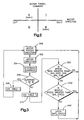
- a four quadrant plot illustrates motor torque command versus motor direction.
- the X-axis shows the motor direction.
- the Y-axis shows the direction of the motor torque command signal.
- Positive values for both motor direction and direction motor torque command is quadrant I, e.g., the motor is moving so as to turn the steerable wheels to the right and the motor torque command is to move the steerable wheels to the right.
- a negative (left) value for the motor direction and a positive value of motor torque command is quadrant II, e.g., the motor is moving so as to turn the steerable wheels to the left and the motor torque command is to move the steerable wheels to the right.
- Negative (left) values for both motor torque command and motor direction is quadrant III, e.g., the motor is moving so as to turn the steerable wheels to the left and the motor torque command is to move the steerable wheels to the left.
- a positive value for the motor direction and a negative (left) value motor torque command is quadrant IV, e.g., the motor is moving so as to turn the steerable wheels to the right and the motor torque command is to move the steerable wheels to the left.
- Different values of retarding torque may be desired depending upon which quadrant the power assist steering system 10 is operating. For example, when the vehicle power assist steering system 10 is operating in quadrants I and III, lower damping may be desired. This is because damping is a retarding torque which decreases the assist provided by the electric assist motor. Greater assist is desired during a turning maneuver than during a return of the steerable wheels to a straight-ahead position. When the power assist steering system 10 is operating in quadrants II and IV, indicating a return of the steerable wheels to a straight-ahead position, higher damping may be desired. This is because the retarding torque during even quadrant operation stabilizes yaw rate as described above.
- different levels of retarding torque may be obtained by providing more than one look-up table.
- a first table may be provided having values for the constants A 1 , A 2 , B 1 , and B 2 for when the power assist steering system is operating in quadrants I and III.
- a second table having higher values for the constants may be provided for when the system is operating in quadrants II and IV.
- a process for control of the damping values including selection of damping tables is fully described in the above-mentioned US-A-5,623,409.
- the present invention provides a stabilized yaw rate control when the steering system is operating in quadrants II or IV and the vehicle speed signal 129 is lost due to, for example, a broken wire.
- the control circuit 220 upon detection of a vehicle speed signal loss, activates an indicator 250 to warn the vehicle operator. Once warned that a failure has occurred in the vehicle steering control system, the vehicle operator can have the vehicle repaired.
- the warning indication can be coupled with a memory and/or timing device to provide the vehicle OEM an indication as to the nature of the steering system failure and the time the vehicle was continued to be operated after the failure indication was provided to the vehicle operator.
- a process for selection of control tables, determination of the loss of the vehicle speed signal, and damping control when the vehicle speed signal 129 is lost is shown in Fig. 3.
- the process starts at step 300 where the motor torque command direction is determined.
- the process then proceeds to step 302 where direction of motor rotation is determined.
- Motor velocity sensor 200 provides a signal to damping control circuit 220 indicating, not only the motor velocity, but also the direction of rotation of motor 26 (velocity has both a magnitude component and a direction component).
- the direction of rotation of motor 26 is indicative of the direction of steering movement of the steerable wheels 22, 24. The process then proceeds to step 304.
- step 304 a determination is made in damping control circuit 220 as to which one of the four possible operating quadrants the power assist steering system 10 is operating.
- step 306 a determination is made as to whether the power assist steering system is operating in quadrants I or III (i.e., the odd quadrants of operation) as opposed to operating in quadrants II or IV. If the determination in step 306 is affirmative (the system is operating in the odd quadrants), the process proceeds to step 308.
- step 308 the first table of control values is selected and used to determine the values of the damping factors K d1 (s), the vehicle speed damping factor, and K d2 (W m ), the assist motor velocity damping factor. The process then returns to step 300.
- step 306 determines whether the determination in step 306 is negative, i.e. the power assist steering system is operating in either quadrant II or IV.
- step 310 the second table of values is selected to determine the values of the damping factors K d1 (s), the vehicle speed damping factor, and K d2 (W m ), the assist motor velocity damping factor. The process then proceeds to step 320.
- the minimum motor rate is equal to 720 mechanical degrees per second which is approximately equal to a hand wheel (steering wheel 12) rate of 20 revolutions per minute.
- the predetermined minimum time period is equal to the tire wrap value divided by the motor rate.
- the tire wrap value is equal to the minimum tire wrap value plus the average unsigned motor torque command value for a period, initially set to one second, divided by the motor torque command value at 50 in-lbs from the zero speed assist table (i.e., maximum assist table) times the maximum tire wrap value.
- the minimum tire wrap value is equal to 20 hand wheel degrees which is equal to 120 motor mechanical degrees for a preferred steering system having a 6:1 ball-nut to pinion ratio.
- tire wrap is the steering effect experienced by the steering system due to the tire (rubber) twisting when the vehicle is steered at park or low speed and the tire tries to untwist.
- the determination is made with regard to a minimum time so as to filter out tire wrap effects from the system's damping control.
- the purpose of determining if the motor rate is greater than a minimum rate for a minimum time period is to provide an indication as to whether the vehicle is moving and should, therefore, have a vehicle speed signal present. If the vehicle is traveling in a normal manner, it can be assumed that certain steering inputs would be applied by the vehicle operator. If the steering inputs are, in fact, applied because of normal vehicle operation while traveling, the determination in step 320 would be affirmative. If the vehicle is stationary and no steering inputs are being applied, the determination in step 320 would be negative. If the determination in step 320 is negative, the process returns to step 300. If the determination in step 320 is affirmative, the process proceeds to step 330.
- step 330 a determination is made as to whether the vehicle sensed speed from signal 129 is greater than a predetermined minimum value.
- the minimum vehicle speed for this determination is 3 kph. Recall that step 330 is entered under the assumption from step 320 that the vehicle is moving and there should, therefore, be a speed signal present. If the determination in step 330 is affirmative, i.e., the vehicle is moving at a speed greater than 3 kph, the process loops back to step 300. The vehicle speed used for damping control will be the measured vehicle speed.
- step 330 If the determination in step 330 is negative, then it is assumed that the vehicle is moving but, for some reason, e.g., a broken wire or bad sensor, the speed signal is lost. Upon the occurrence of a lost speed signal, the process proceeds to step 340.
- damping is controlled in quadrants II and IV in accordance with a predetermined damping state.
- a safe speed i.e., a default speed value, is latched into memory in step 340. This safe speed or default speed value is then used for at least the damping control for the even quadrant steering operation. The process then returns to step 300.
- the sensed vehicle speed at that time will be used for the damping control instead of the default value.
- the default value for vehicle speed that is used upon the loss of the sensed vehicle speed signal can be empirically determined for a vehicle platform of interest so as to provide a default steering feel.
- the present invention is not limited to damping in response to a predetermined speed value upon the loss of the vehicle speed signal. In accordance with the present invention, loss of the vehicle speed signal results in the occurrence of a predetermined damping state.
- the indicator 250 in the vehicle compartment can be actuated to inform the vehicle operator of a fault condition in the steering system.
- other devices such as memory devices (EEPROM, flash memory, etc.), can be used to record the time of occurrence of the fault condition or the lapsed time after activation of the warning indicator.
Landscapes
- Engineering & Computer Science (AREA)
- Chemical & Material Sciences (AREA)
- Combustion & Propulsion (AREA)
- Transportation (AREA)
- Mechanical Engineering (AREA)
- Steering Control In Accordance With Driving Conditions (AREA)
- Power Steering Mechanism (AREA)
Claims (12)
- Eine elektrische Servolenkvorrichtung (10), die Folgendes aufweist:Mittel (119) zum Abfühlen der Fahrzeuggeschwindigkeit und zum Vorsehen eines Fahrzeuggeschwindigkeitsignals (129); undMittel zum Bestimmen des Auftretens eines Verlustes des Fahrzeuggeschwindigkeitssignals (129) und zum Vorsehen eines Signals, das eine Anzeige dafür bildet; gekennzeichnet durch:Mittel (220) zum Steuern der Dämpfung der elektrischen Servolenkvorrichtung (10) ansprechend auf das Fahrzeuggeschwindigkeitssignal (129) und wobei die Mittel zum Bestimmen des Auftretens dieses Verlustes das Signal liefern, das einen Verlust des Fahrzeuggeschwindigkeitssignal (129) anzeigt, Steuern der Dämpfung gemäß einem vorbestimmten Dämpfungswert.
- Vorrichtung nach Anspruch 1, wobei der vorbestimmte Dämpfungswert einem Dämpfungswert bei einem vorbestimmten Fahrzeuggeschwindigkeitswert entspricht.
- Vorrichtung nach Anspruch 1, wobei die Vorrichtung (10) einen Elektrohilfsmotor (26) umfasst und die Mittel zum Bestimmen des Auftretens eines Verlusts von dem Fahrzeuggeschwindigkeitssignal Mittel umfassen zum Bestimmen, ob ein Betriebsrate des Elektrohilfsmotors (26) größer ist als ein vorbestimmter Wert von einer vorbestimmten Zeitperiode.
- Vorrichtung nach Anspruch 3, die ferner Folgendes aufweist:Mittel (250) zum Vorsehen einer Warnanzeige, wenn die Bestimmungsmittel bestimmen, dass die Betriebsrate des Elektrohilfsmotors (26) größer als ein vorbestimmter Wert für eine vorbestimmte Zeitperiode ist und die Mittel (119) zum Abfühlen der Fahrzeuggeschwindigkeit kein Fahrzeuggeschwindigkeitssignal (129) vorsehen, das anzeigt, dass die Fahrzeuggeschwindigkeit größer als ein vorbestimmter Wert ist.
- Vorrichtung nach Anspruch 1, die ferner Folgendes aufweist:wobei die Mittel (220) zum Steuern der Dämpfung des Elektrohilfsmotors (26) ferner die Dämpfung ansprechend auf das Motordrehzahlsignal (201) steuern.Drehmomentabfühlmittel (110) zum Abfühlen des angelegten Lenkdrehmoments und zum Vorsehen eines darauf ansprechenden Lenkdrehmomentsignals;Mittel zum Vorsehen eines Drehmomentanforderungssignals, das einen Wert mit funktionsmäßigem Bezug zu dem angelegten Drehmoment besitzt;einen Elektrohilfsmotor (26), der betriebsmäßig mit einem Lenkglied verbunden ist, um, wenn erregt, Hilfslenkkraft vorzusehen;Mittel (150) zum Vorsehen eines Motorsteuersignals, ansprechend auf das Drehmomentanforderungssignal;Motordrehzahlabfühlmittel (200) zum Abfühlen der Drehzahl des Elektrohilfsmotors (26) und zum Vorsehen eines Motordrehzahlsignals (201), das eine Anzeige dafür bildet;
- Vorrichtung nach Anspruch 5, wobei der vorbestimmte Dämpfungswert einem Dämpfungswert bei einem vorbestimmten Fahrzeuggeschwindigkeitswert entspricht.
- Ein Verfahren zum Steuern einer elektrischen Servolenkvorrichtung (10), das folgende Schritte aufweist:Abfühlen der Fahrzeuggeschwindigkeit und Vorsehen eines Fahrzeuggeschwindigkeitsignals (129); undBestimmen des Auftretens eines Verlustes des Fahrzeuggeschwindigkeitsignals (129) und Vorsehen eines Signals, das eine Anzeige dafür bildet; gekennzeichnet durch:Steuern der Dämpfung des elektrischen Servolenksystems (10), ansprechend auf das Fahrzeuggeschwindigkeitssignal (129) und, wenn der Schritt des Abfühlens eines Verlustes das Signal vorsieht, das einen Verlust des Fahrzeuggeschwindigkeitssignals (129) anzeigt, Steuern der Dämpfung gemäß einem vorbestimmten Dämpfungswert
- Verfahren nach Anspruch 7, wobei die Lenkvorrichtung (10) einen Elektrohilfsmotor (26) umfasst und der Schritt des Bestimmens des Auftretens eines Verlustes des Fahrzeuggeschwindigkeitsignals (129) das Bestimmen umfasst, ob eine Betriebsrate des Elektrohilfsmotors (26) größer ist als ein vorbestimmter Wert für eine vorbestimmte Zeitperiode.
- Verfahren nach Anspruch 7, wobei der Schritt des Steuerns der Dämpfung ansprechend auf einen vorbestimmten Dämpfungswert das Auswählen eines Dämpfungswertes umfasst, der einem vorbestimmten Fahrzeuggeschwindigkeitswert entspricht.
- Verfahren nach Anspruch 7, das ferner die folgenden Schritte aufweist:wobei der Schritt des Steuerns der Dämpfung des Elektrohilfsmotors (26) ferner auf das Motordrehzahlsignal (201) und die abgefühlte Fahrzeuggeschwindigkeit anspricht.Abfühlen des angelegten Lenkdrehmoments und Vorsehen eines eine Anzeige dafür bildenden Lenkdrehmomentsignals;Vorsehen eines Drehmomentanforderungssignals, das einen Wert besitzt, das einen funktionsmäßigen Bezug zu dem angelegten Lenkdrehmoment besitzt;Vorsehen eines Elektrohilfsmotors (26), der betriebsmäßig mit einem Lenkglied (20) verbunden ist, um, wenn erregt, Hilfslenkkraft vorzusehen;Vorsehen eines Motorsteuersignals ansprechend auf das Drehmomentanforderungssignal;Abfühlen der Drehzahl des Elektrohilfsmotors (26) und Vorsehen eines dafür einen Anzeige bildenden Motordrehzahlsignals (201);
- Verfahren nach Anspruch 10, wobei der Schritt der Dämpfungssteuerung ansprechend auf einen vorbestimmten Dämpfungswert das Auswählen eines Dämpfungswerts ansprechend auf einen vorbestimmten Fahrzeuggeschwindigkeitswert umfasst.
- Verfahren nach Anspruch 8, das ferner folgenden Schritt umfasst:Vorsehen einer Warnanzeige, wenn der Bestimmungsschritt, ob eine Betriebsrate des Elektrohilfsmotors (26) größer als ein vorbestimmter Wert für eine vorbestimmte Zeitperiode ist, bestimmt, dass die Betriebsrate des Elektrohilfsmotors (26) größer als der vorbestimmte Wert für eine vorbestimmte Zeitperiode ist und der Schritt des Abfühlens kein Fahrzeuggeschwindigkeitssignal (129) liefert, das eine Anzeige dafür bildet, dass die Fahrzeuggeschwindigkeit größer als ein vorbestimmter Wert ist.
Applications Claiming Priority (2)
| Application Number | Priority Date | Filing Date | Title |
|---|---|---|---|
| US08/843,416 US5992556A (en) | 1997-04-15 | 1997-04-15 | Method and apparatus for damping control of an electric assist steering system with vehicle speed signal loss feature |
| US843416 | 1997-04-15 |
Publications (3)
| Publication Number | Publication Date |
|---|---|
| EP0872406A2 EP0872406A2 (de) | 1998-10-21 |
| EP0872406A3 EP0872406A3 (de) | 2000-12-27 |
| EP0872406B1 true EP0872406B1 (de) | 2004-07-07 |
Family
ID=25289909
Family Applications (1)
| Application Number | Title | Priority Date | Filing Date |
|---|---|---|---|
| EP98105435A Expired - Lifetime EP0872406B1 (de) | 1997-04-15 | 1998-03-25 | Verfahren und Vorrichtung zur Dämpfungskontrolle einer elektrischen Servolenkung mit Besonderheiten bei Verlust des Fahrzeuggeschwindigkeitssignals |
Country Status (5)
| Country | Link |
|---|---|
| US (1) | US5992556A (de) |
| EP (1) | EP0872406B1 (de) |
| JP (1) | JP2945895B2 (de) |
| BR (1) | BR9801047A (de) |
| DE (1) | DE69824911T2 (de) |
Cited By (1)
| Publication number | Priority date | Publication date | Assignee | Title |
|---|---|---|---|---|
| US7549504B2 (en) | 2006-07-28 | 2009-06-23 | Delphi Technologies, Inc. | Quadrant dependent active damping for electric power steering |
Families Citing this family (40)
| Publication number | Priority date | Publication date | Assignee | Title |
|---|---|---|---|---|
| JP2998929B2 (ja) * | 1997-08-18 | 2000-01-17 | 本田技研工業株式会社 | 電動パワーステアリング装置 |
| JP3344463B2 (ja) * | 1998-04-27 | 2002-11-11 | トヨタ自動車株式会社 | 車両用操舵制御装置 |
| US6240350B1 (en) * | 1998-07-24 | 2001-05-29 | Nsk Ltd. | Control apparatus for electric power steering system |
| GB9919277D0 (en) * | 1999-08-17 | 1999-10-20 | Trw Lucas Varity Electric | Method and apparatus for controlling an electric power assisted steering system using an adaptive blending torque filter |
| EP1219015A4 (de) | 1999-09-17 | 2006-05-10 | Delphi Tech Inc | Permament magnet motor regler mit geringer welligkeit |
| US6631925B1 (en) * | 2000-02-14 | 2003-10-14 | William M. Lawson, Jr. | Miniaturized motor vehicle |
| US6647329B2 (en) | 2000-04-07 | 2003-11-11 | Delphi Technologies, Inc. | Damping of voltage-controlled brushless motors for electric power steering systems |
| JP2002002514A (ja) * | 2000-06-16 | 2002-01-09 | Unisia Jecs Corp | 電動モータ駆動式操舵補助装置の異常判定装置 |
| US6498451B1 (en) | 2000-09-06 | 2002-12-24 | Delphi Technologies, Inc. | Torque ripple free electric power steering |
| US6566829B1 (en) | 2000-09-07 | 2003-05-20 | Delphi Technologies, Inc. | Method and apparatus for torque control of a machine |
| US6931311B2 (en) * | 2001-02-07 | 2005-08-16 | Visteon Global Technologies, Inc. | Torque sensing for a steering system |
| JP3622956B2 (ja) * | 2001-05-11 | 2005-02-23 | 本田技研工業株式会社 | 電動パワーステアリング装置 |
| WO2002100704A2 (en) | 2001-06-08 | 2002-12-19 | Delphi Technologies, Inc. | Velocity compensation control for electric steering systems |
| US6640172B2 (en) | 2001-08-01 | 2003-10-28 | Delphi Technologies, Inc. | Dual gain algorithm for four wheel steering system |
| US6701237B2 (en) | 2001-08-01 | 2004-03-02 | Delphi Technologies, Inc. | Vehicle speed diagnostic algorithm for four-wheel steering systems |
| US7071649B2 (en) | 2001-08-17 | 2006-07-04 | Delphi Technologies, Inc. | Active temperature estimation for electric machines |
| US6900607B2 (en) * | 2001-08-17 | 2005-05-31 | Delphi Technologies, Inc. | Combined feedforward and feedback parameter estimation for electric machines |
| US7199549B2 (en) * | 2001-08-17 | 2007-04-03 | Delphi Technologies, Inc | Feedback parameter estimation for electric machines |
| US20030076064A1 (en) * | 2001-08-17 | 2003-04-24 | Kleinau Julie A. | Feedforward parameter estimation for electric machines |
| US7576506B2 (en) | 2001-12-11 | 2009-08-18 | Delphi Technologies, Inc. | Feedforward parameter estimation for electric machines |
| JP3865631B2 (ja) * | 2001-12-26 | 2007-01-10 | 株式会社ジェイテクト | 電動パワーステアリング装置 |
| US6789641B2 (en) | 2002-08-14 | 2004-09-14 | Trw Inc. | Method and apparatus for controlling an electric assist motor using a modified blending filter |
| US7157878B2 (en) * | 2002-11-19 | 2007-01-02 | Delphi Technologies, Inc. | Transient compensation voltage estimation for feedforward sinusoidal brushless motor control |
| JP4131393B2 (ja) * | 2003-02-17 | 2008-08-13 | 株式会社デンソー | 電動パワーステアリングの制御装置 |
| US20040189228A1 (en) * | 2003-03-28 | 2004-09-30 | Gregory Katch | Vehicle speed dependent compensator for electric steering systems |
| DE102004009821A1 (de) * | 2004-02-28 | 2005-09-22 | Zf Lenksysteme Gmbh | Verfahren zum Betrieb eines Lenksystems mit Konfiguration von Nutzanwendungen |
| US6949901B1 (en) * | 2004-08-30 | 2005-09-27 | Delphi Technologies, Inc. | System and method for controlling a steering position of rear vehicle wheels |
| US7163080B2 (en) * | 2005-03-11 | 2007-01-16 | Trw Automotive U.S. Llc | Method and apparatus for detecting a failed temperature sensor in an electric assist steering system |
| JP4761023B2 (ja) * | 2005-03-15 | 2011-08-31 | 株式会社ジェイテクト | ブラシレスモータの制御装置 |
| DE102006007610A1 (de) * | 2006-02-14 | 2007-08-16 | Brose Fahrzeugteile Gmbh & Co. Kommanditgesellschaft, Coburg | Antriebseinrichtung für eine Verstelleinrichtung zum Verstellen eines Fahrzeugteils und Verfahren zum Betrieb einer Antriebseinrichtung |
| US7543679B2 (en) | 2006-07-28 | 2009-06-09 | Delphi Technologies, Inc. | Compensation of periodic sensor errors in electric power steering systems |
| US7725227B2 (en) * | 2006-12-15 | 2010-05-25 | Gm Global Technology Operations, Inc. | Method, system, and apparatus for providing enhanced steering pull compensation |
| JP4281828B2 (ja) | 2007-08-08 | 2009-06-17 | トヨタ自動車株式会社 | 電動パワーステアリング装置 |
| US8296011B2 (en) * | 2007-12-12 | 2012-10-23 | Steering Solutions IP Holding Corporations | Systems and methods involving quadrant dependent active damping |
| US20090200099A1 (en) * | 2008-02-11 | 2009-08-13 | Ray Tat-Lung Wong | Electric power steering control system |
| US8996250B2 (en) * | 2011-09-09 | 2015-03-31 | Steering Solutions Ip Holding Corporation | Inertia compensation with frequency dependent damping |
| DE102013111168A1 (de) * | 2013-10-09 | 2015-04-09 | Trw Automotive Gmbh | Verfahren zur Steuerung eines Elektromotors eines Servo-Lenksystems sowie Servo-Lenksystem |
| JP6740647B2 (ja) | 2016-03-10 | 2020-08-19 | 株式会社ジェイテクト | 操舵制御装置 |
| CN108407886B (zh) * | 2018-03-06 | 2020-01-21 | 北京汽车股份有限公司 | 车辆电动助力转向系统的低电压报警方法、装置和车辆 |
| JP7319957B2 (ja) * | 2020-12-25 | 2023-08-02 | 本田技研工業株式会社 | 移動体 |
Family Cites Families (20)
| Publication number | Priority date | Publication date | Assignee | Title |
|---|---|---|---|---|
| US3983953A (en) * | 1971-07-28 | 1976-10-05 | Gemmer-France | Servo mechanism |
| US4415054A (en) * | 1982-08-05 | 1983-11-15 | Trw Inc. | Steering gear |
| US4554607A (en) * | 1982-09-29 | 1985-11-19 | Dana Corporation | Fuse loss indicating circuit |
| US4660671A (en) * | 1985-10-23 | 1987-04-28 | Trw Inc. | Electric steering gear |
| JPH0796388B2 (ja) * | 1987-04-13 | 1995-10-18 | 株式会社日立製作所 | 電動式パワ−ステアリング装置 |
| JP2604620B2 (ja) * | 1988-03-15 | 1997-04-30 | 富士重工業株式会社 | 車両用動力操舵装置の制御装置 |
| JPH0350074A (ja) * | 1989-04-22 | 1991-03-04 | Mitsubishi Electric Corp | モータ駆動式パワー・ステアリング装置 |
| JP2583468Y2 (ja) * | 1991-09-13 | 1998-10-22 | 光洋精工株式会社 | パワーステアリング装置 |
| JPH05105100A (ja) * | 1991-09-27 | 1993-04-27 | Honda Motor Co Ltd | 車両の操舵装置 |
| US5442956A (en) * | 1992-06-03 | 1995-08-22 | Trw Inc. | Torque sensor for a power assist steering system |
| US5257828A (en) * | 1992-06-03 | 1993-11-02 | Trw Inc. | Method and apparatus for controlling damping in an electric assist steering system for vehicle yaw rate control |
| US5528497A (en) * | 1992-09-16 | 1996-06-18 | Honda Giken Kogyo Kabushiki Kaisha | Vehicle steering control system |
| JP3061961B2 (ja) * | 1992-09-16 | 2000-07-10 | 本田技研工業株式会社 | 車両用操舵装置 |
| US5504679A (en) * | 1993-02-15 | 1996-04-02 | Mitsubishi Denki Kabushiki Kaisha | Control apparatus for motor-driven power steering system of motor vehicle |
| JPH0710013A (ja) * | 1993-06-28 | 1995-01-13 | Kayaba Ind Co Ltd | 電動パワーステアリング装置 |
| US5568389A (en) * | 1994-03-11 | 1996-10-22 | Trw Inc. | Method and apparatus for controlling an electric assist steering system |
| US5473231A (en) * | 1994-05-11 | 1995-12-05 | Trw Inc. | Method and apparatus for controlling an electric assist steering system using an adaptive torque filter |
| US5623409A (en) * | 1994-10-31 | 1997-04-22 | Trw Inc. | Method and apparatus for non-linear damping of an electric assist steering system for vehicle yaw rate control |
| US5709281A (en) * | 1995-09-14 | 1998-01-20 | Trw Inc. | Method and apparatus for adjusting steering feel |
| US5743351A (en) * | 1996-05-29 | 1998-04-28 | Trw Inc. | Method and apparatus for controlling an electric assist steering sysem by linearizing system input-output torque gain |
-
1997
- 1997-04-15 US US08/843,416 patent/US5992556A/en not_active Expired - Lifetime
-
1998
- 1998-03-25 DE DE69824911T patent/DE69824911T2/de not_active Expired - Lifetime
- 1998-03-25 EP EP98105435A patent/EP0872406B1/de not_active Expired - Lifetime
- 1998-04-10 JP JP10098656A patent/JP2945895B2/ja not_active Expired - Lifetime
- 1998-04-14 BR BR9801047-6A patent/BR9801047A/pt not_active IP Right Cessation
Cited By (1)
| Publication number | Priority date | Publication date | Assignee | Title |
|---|---|---|---|---|
| US7549504B2 (en) | 2006-07-28 | 2009-06-23 | Delphi Technologies, Inc. | Quadrant dependent active damping for electric power steering |
Also Published As
| Publication number | Publication date |
|---|---|
| JP2945895B2 (ja) | 1999-09-06 |
| EP0872406A2 (de) | 1998-10-21 |
| BR9801047A (pt) | 2001-03-20 |
| JPH10287265A (ja) | 1998-10-27 |
| EP0872406A3 (de) | 2000-12-27 |
| DE69824911D1 (de) | 2004-08-12 |
| US5992556A (en) | 1999-11-30 |
| DE69824911T2 (de) | 2005-08-25 |
Similar Documents
| Publication | Publication Date | Title |
|---|---|---|
| US5992556A (en) | Method and apparatus for damping control of an electric assist steering system with vehicle speed signal loss feature | |
| EP0671310B1 (de) | Verfahren und Vorrichtung zur Steuerung eines Hilfskraftlenksystems | |
| EP0710599B1 (de) | Verfahren und Vorrichtung zur Regelung eines elektrischen Hilfskraft-Lenksystems mit einer zwei-dimensionalen Interpolation für Stromwerte | |
| EP1607303B1 (de) | Fahrzeuglenkung | |
| EP0857638B1 (de) | Kraftfahrzeuglenkung | |
| EP0858942B1 (de) | Lenkeinrichtung für ein Fahrzeug | |
| EP1112912B1 (de) | Vorrichtung und Verfahren zur Feststellung einer Überlastung eines Motors in einem elektrischen Hilfskraft-Lenksystem | |
| EP0190678B1 (de) | Elektromotorisches Servolenkverfahren und System | |
| EP0810143A2 (de) | Verfahren und Vorrichtung zur Steuerung eines elektrischen Servo-Lenksystems durch Linearisierung der Systemverstärkung des Eingangs/- Ausgangs-Drehmoments | |
| EP1538065B1 (de) | Lenksteuervorrichtung mit rückstelldrehmomentsteuerung | |
| JP3593898B2 (ja) | 操舵制御装置 | |
| EP0477820B1 (de) | Hinterradlenkungsvorrichtung | |
| US6686835B2 (en) | Rear wheel steering angle control apparatus | |
| JPH06127412A (ja) | 電動式パワーステアリング装置 | |
| JPH11301509A (ja) | 電動パワーステアリング装置 | |
| JP2597939Y2 (ja) | パワーステアリング装置 | |
| JP3282293B2 (ja) | 電動式パワーステアリング装置 | |
| JPS61119475A (ja) | 電動機式動力舵取装置 | |
| JPH06312666A (ja) | 動力操舵装置 | |
| JP2998214B2 (ja) | 電動式パワーステアリング装置 | |
| JPH10278827A (ja) | 電動式パワーステアリングの戻り制御装置 | |
| JP2004090878A (ja) | 電動パワーステアリング装置 | |
| JPH0714108Y2 (ja) | 電気式動力舵取装置 | |
| JP2006160010A (ja) | 電動パワーステアリング装置 | |
| JPH10278829A (ja) | 電動式パワーステアリングの戻り制御装置 |
Legal Events
| Date | Code | Title | Description |
|---|---|---|---|
| PUAI | Public reference made under article 153(3) epc to a published international application that has entered the european phase |
Free format text: ORIGINAL CODE: 0009012 |
|
| AK | Designated contracting states |
Kind code of ref document: A2 Designated state(s): DE FR GB IT |
|
| AX | Request for extension of the european patent |
Free format text: AL;LT;LV;MK;RO;SI |
|
| PUAL | Search report despatched |
Free format text: ORIGINAL CODE: 0009013 |
|
| AK | Designated contracting states |
Kind code of ref document: A3 Designated state(s): AT BE CH DE DK ES FI FR GB GR IE IT LI LU MC NL PT SE |
|
| AX | Request for extension of the european patent |
Free format text: AL;LT;LV;MK;RO;SI |
|
| RIC1 | Information provided on ipc code assigned before grant |
Free format text: 7B 62D 6/00 A, 7B 62D 5/04 B, 7B 62D 101:00 Z, 7B 62D 119:00 Z, 7B 62D 153:00 Z |
|
| 17P | Request for examination filed |
Effective date: 20010620 |
|
| AKX | Designation fees paid |
Free format text: DE FR GB IT |
|
| 17Q | First examination report despatched |
Effective date: 20020403 |
|
| GRAP | Despatch of communication of intention to grant a patent |
Free format text: ORIGINAL CODE: EPIDOSNIGR1 |
|
| RAP1 | Party data changed (applicant data changed or rights of an application transferred) |
Owner name: TRW AUTOMOTIVE U.S. LLC |
|
| GRAS | Grant fee paid |
Free format text: ORIGINAL CODE: EPIDOSNIGR3 |
|
| GRAA | (expected) grant |
Free format text: ORIGINAL CODE: 0009210 |
|
| AK | Designated contracting states |
Kind code of ref document: B1 Designated state(s): DE FR GB IT |
|
| REG | Reference to a national code |
Ref country code: GB Ref legal event code: FG4D |
|
| REF | Corresponds to: |
Ref document number: 69824911 Country of ref document: DE Date of ref document: 20040812 Kind code of ref document: P |
|
| ET | Fr: translation filed | ||
| PLBE | No opposition filed within time limit |
Free format text: ORIGINAL CODE: 0009261 |
|
| STAA | Information on the status of an ep patent application or granted ep patent |
Free format text: STATUS: NO OPPOSITION FILED WITHIN TIME LIMIT |
|
| 26N | No opposition filed |
Effective date: 20050408 |
|
| PGFP | Annual fee paid to national office [announced via postgrant information from national office to epo] |
Ref country code: GB Payment date: 20090206 Year of fee payment: 12 |
|
| PGFP | Annual fee paid to national office [announced via postgrant information from national office to epo] |
Ref country code: IT Payment date: 20090318 Year of fee payment: 12 |
|
| PGFP | Annual fee paid to national office [announced via postgrant information from national office to epo] |
Ref country code: FR Payment date: 20090306 Year of fee payment: 12 |
|
| GBPC | Gb: european patent ceased through non-payment of renewal fee |
Effective date: 20100325 |
|
| REG | Reference to a national code |
Ref country code: FR Ref legal event code: ST Effective date: 20101130 |
|
| PG25 | Lapsed in a contracting state [announced via postgrant information from national office to epo] |
Ref country code: FR Free format text: LAPSE BECAUSE OF NON-PAYMENT OF DUE FEES Effective date: 20100331 |
|
| PG25 | Lapsed in a contracting state [announced via postgrant information from national office to epo] |
Ref country code: GB Free format text: LAPSE BECAUSE OF NON-PAYMENT OF DUE FEES Effective date: 20100325 Ref country code: IT Free format text: LAPSE BECAUSE OF NON-PAYMENT OF DUE FEES Effective date: 20100325 |
|
| PGFP | Annual fee paid to national office [announced via postgrant information from national office to epo] |
Ref country code: DE Payment date: 20170329 Year of fee payment: 20 |
|
| REG | Reference to a national code |
Ref country code: DE Ref legal event code: R071 Ref document number: 69824911 Country of ref document: DE |