EP0872592A2 - Vorrichtung zur Behandlung einer Faserstoffbahn sowie Dichtungseinrichtung für eine solche Vorrichtung - Google Patents
Vorrichtung zur Behandlung einer Faserstoffbahn sowie Dichtungseinrichtung für eine solche Vorrichtung Download PDFInfo
- Publication number
- EP0872592A2 EP0872592A2 EP98101518A EP98101518A EP0872592A2 EP 0872592 A2 EP0872592 A2 EP 0872592A2 EP 98101518 A EP98101518 A EP 98101518A EP 98101518 A EP98101518 A EP 98101518A EP 0872592 A2 EP0872592 A2 EP 0872592A2
- Authority
- EP
- European Patent Office
- Prior art keywords
- sealing
- web
- fibrous web
- sealing plate
- support band
- Prior art date
- Legal status (The legal status is an assumption and is not a legal conclusion. Google has not performed a legal analysis and makes no representation as to the accuracy of the status listed.)
- Granted
Links
- 238000007789 sealing Methods 0.000 title claims abstract description 108
- 239000011111 cardboard Substances 0.000 claims abstract description 4
- 239000011087 paperboard Substances 0.000 claims abstract description 4
- 238000001035 drying Methods 0.000 claims description 17
- 238000009423 ventilation Methods 0.000 claims description 5
- 239000004033 plastic Substances 0.000 claims description 4
- 229920003023 plastic Polymers 0.000 claims description 4
- 229920002430 Fibre-reinforced plastic Polymers 0.000 claims description 3
- 239000002131 composite material Substances 0.000 claims description 3
- 239000004744 fabric Substances 0.000 claims description 3
- 239000011151 fibre-reinforced plastic Substances 0.000 claims description 3
- 239000002184 metal Substances 0.000 claims description 3
- 239000003381 stabilizer Substances 0.000 claims description 2
- 238000004378 air conditioning Methods 0.000 claims 1
- 239000000123 paper Substances 0.000 description 4
- 238000005299 abrasion Methods 0.000 description 3
- 230000002452 interceptive effect Effects 0.000 description 2
- 235000013580 sausages Nutrition 0.000 description 2
- 230000009760 functional impairment Effects 0.000 description 1
- 230000002093 peripheral effect Effects 0.000 description 1
- 210000002268 wool Anatomy 0.000 description 1
Images
Classifications
-
- D—TEXTILES; PAPER
- D21—PAPER-MAKING; PRODUCTION OF CELLULOSE
- D21F—PAPER-MAKING MACHINES; METHODS OF PRODUCING PAPER THEREON
- D21F5/00—Dryer section of machines for making continuous webs of paper
- D21F5/02—Drying on cylinders
- D21F5/04—Drying on cylinders on two or more drying cylinders
Definitions
- the invention relates to a device for treating a fibrous web such as in particular a paper and / or cardboard web in which the fibrous web alone or together with at least one support band like in particular a drainage belt, press belt, screen belt and / or the like performed over at least one moving or stationary support surface is and on the side facing away from such a support surface Fibrous web at least one sealing device is provided to at least most of it through the fibrous web or a support band to strip off the air boundary layer that has been dragged along. It also concerns one Sealing device according to the preamble of claim 24, for example can be used in such a device.
- the aim of the invention is to provide a device of the type mentioned create their sealing device especially at higher operating speeds always ensures optimal tightness and against interfering objects such as in particular pieces of paper or the like is insensitive.
- a suitable sealing device is also to be provided will.
- the sealing device is a flat or at least in sections includes curved sealing plate, which is preferably elastic is formed and / or resiliently mounted. It can the sealing device preferably one against the fibrous web or a support band can be pressed flat or at least partially curved Include sealing plate, which is preferably elastic and / or resiliently resilient against the fibrous web or that Support band is pressed.
- the device can also be used in particular be provided with such a sealing device, as set out in the claims 24 to 27 is specified.
- the contact pressure is preferably adjustable. Additionally or alternatively can also be provided means for automatic adjustment of the contact pressure be. It is therefore independent of the respective operating conditions always an optimal operation or an optimal tightness guaranteed.
- the sealing plate extends transversely to the web running direction.
- This sealing plate can in particular be made of metal, plastic, fiber-reinforced Plastic or a composite material exist.
- sealing plate is pivotally mounted is.
- the sealing plate can in particular also be removed from the relevant one Support surface can be pivoted away, for example, unhindered to be able to pull in a new support band.
- the sealing plate is preferably releasably attached to a pivotable bracket.
- the Sealing device or its sealing plate can thus can be replaced easily and quickly if necessary.
- the sealing plate in particular mechanically, pneumatically and / or hydraulically pressed.
- sealing plate via at least one linkage, at least one pressure screw, at least one spring and / or the like.
- pneumatic and / or hydraulic pressure is the sealing plate preferably by at least one cylinder / piston unit actable.
- the sealing device can, for example, in the inlet area Steam blow box may be provided. With a practical practical Version is provided in the inlet area of a steam blow box, which is arranged on the outer circumference of a press roll over which the fibrous web and optionally the support band is guided.
- the sealing device is expediently on the steam blow box attached or pivotally mounted.
- the sealing device can for example also in the drain area Drying cylinder can be provided in which the fibrous web and a Support tape from the drying cylinder to run in particular one perforated through an outer suction box and / or grooved deflection roller to be fed.
- the sealing device is preferably in front in the web running direction arranged the drain area.
- the sealing device is assigned to such a suction box, then can be attached to this suction box or swiveled be stored. Also when using other ventilation systems can the sealing device on the relevant ventilation Device may be appropriate.
- the sealing plate is located with an edge region extending transversely to the web running direction the fibrous web or a respective support tape while in Area of its opposite edge is preferably pivotally mounted is.
- the sealing device according to the invention is characterized in that that the sealing element is elastic and / or resilient is stored and / or additional means are provided around the sealing element at least then at a minimal distance from the web or to hold the support band when the web or the support band is a predetermined Has reached operating speed.
- Advantageous further training the sealing device are in the relevant subclaims specified.
- Such a sealing device is also in particular the previously specified device can be used.
- an inlet gap is formed.
- Sealing With such a sealing device, a dynamic one can in particular Sealing can be achieved, which also suitable for stabilizers is.
- the sealing element increases with increasing web speeds lifted off by part of the air boundary layer so that contact-free sealing at least during normal operation results, whereby abrasion is avoided. At most it will be a Smaller air volume flow let through, which is no longer annoying is. The main flow is blocked in any case. Basically is it is also possible to have the sealing element from the outset in a minimal Keep distance from the web or the support band.
- Such a dynamic seal can advantageously in particular can be achieved in that the sealing element is elastic and / or is resiliently mounted. It can thus, for example only an elastic design of the sealing element is provided be. Alternatively or additionally, the sealing element can be resilient be stored. If the sealing element is resiliently mounted, so it itself also be relatively rigid, so that the required flexibility is achieved primarily by the resilient mounting. Alternatively or in addition, additional means can also be provided to the sealing element at least then at a minimal distance from the To hold the web or the support band when the web or the support band has reached a predefinable operating speed.
- the sealing element can start up if a support band is used such as a dryer fabric the back of the support bath touch. This contact may only be brief.
- part of the air boundary layer preferably lifts flexible and / or resiliently mounted seal.
- the air boundary layer carried along with the support band is scraped or stripped for the most part, so that at most a small part of the limit air flow reaches the room to be evacuated. If a so-called "paper sausage” goes through the machine when it breaks off, so gives way to the elastically designed and / or resiliently mounted Sealing element.
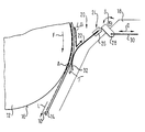
- the device in question is used to treat a fibrous web 10 such as in particular a paper and / or cardboard web.
- a drying cylinder 12 of the drying section is partially shown in the figure, which turns in the direction of arrow F and over the together with the fibrous web 10, a support band 14 is guided, which in the present Case is formed by a dryer fabric.
- This together with the fibrous web 10 via the drying cylinder 12 guided support belt 14 runs with the fibrous web 10 in a drain area A from that through the outer peripheral surface of the drying cylinder 12 formed support surface 16 to then, for example, in the web running direction L. one by an only indicated external suction box 18 suction perforated and / or grooved, not shown here Deflection roller to be fed.
- a sealing device 20 is provided, which in the present case in the web running direction L before the run-off area A is arranged.
- This sealing device 20 is used in the illustrated Embodiment for this, at least the majority of one by to strip off the outer support band 14 entrained air boundary layer.
- the fibrous web 10 lies between the support belt 14 and the drying cylinder 12 so that they at least at standstill and low speeds with the drying cylinder 12 comes into direct contact.
- the sealing device 20 comprises a pressable against the support band 14 flat or at least sectionally curved sealing plate 22, which is preferably elastic and / or resilient can be pressed against the support band 14.
- This sealing plate 22 which extends transversely to the web running direction L.
- This sealing plate 22 can for example made of metal, plastic, fiber-reinforced plastic or a composite material.
- the sealing plate 22 is on her upper, extending transversely to the web running direction L edge detachable fixed in a bracket 24 which is transverse to the web running direction L extending axis S is pivotally attached to the suction box 18.
- the upper edge of the sealing plate 22 is preferably releasable in a fork-shaped receptacle 26 of the pivotable bracket 24.
- the pivotable bracket 24 further includes at least one tab 28, with its free end, for example, a linkage 30 is coupled, the according to the double arrow D in two opposite to each other Is adjustable to the sealing plate 22 by a corresponding Pivot about the axis S to press the support belt 14 or remove from it.
- the sealing plate 22 also lies their free edge region extending transversely to the web running direction L. 32 on the support belt 14, the system in the web running direction L somewhat before the run-up area A.
- the support belt 14 adjacent edge area 32 at least when the sealing plate 22 is pressed on in the manner shown in the contact or swivel plane bent.
- the contact pressure is preferably adjustable.
- the sealing device 22 expediently designed so that an automatic This contact pressure is adjusted.
- the sealing device 20 inter alia prevents that a larger proportion of those carried by the support band 14 Air in the area of the outside, not shown here Deflection roller arrives so that the vacuum to be generated in the suction box 18 and thus the energy required to generate negative pressure can be kept low.
- part of the air boundary layer LG preferably lifts flexible and / or resiliently mounted sealing plate 22 from what is supported in the present case by the fact that between the sealing plate 22 and the support band 14 formed an inlet gap becomes.
- the entrained with the support band 14 Air boundary layer LG is largely scraped off or stripped off, so that at most a small part T of the limit air flow in the to be evacuated Space. Goes a so-called "paper sausage” in a demolition through the machine, so the elastic and / or resilient gives way resiliently mounted sealing plate 22.
Landscapes
- Paper (AREA)
Abstract
Description
- 10
- Faserstoffbahn
- 12
- Trockenzylinder
- 14
- Stützband
- 16
- Stützfläche
- 18
- Saugkasten
- 20
- Dichtungseinrichtung
- 22
- Dichtungsplatte
- 24
- Halterung
- 26
- gabelförmige Aufnahme
- 28
- Lasche
- 30
- Gestänge
- 32
- Randbereich
- A
- Ablaufbereich
- D
- Doppelpfeil
- F
- Pfeil
- L
- Bahnlaufrichtung
- S
- Schwenkachse
- LG
- Luftgrenzschicht
- T
- kleiner Teil
Claims (28)
- Vorrichtung zur Behandlung einer Faserstoffbahn (10) wie insbesondere einer Papier- und/oder Kartonbahn, in der die Faserstoffbahn (10) alleine oder zusammen mit wenigstens einem Stützband (14) wie insbesondere einem Entwässerungsband, Preßband, Siebband und/oder dergleichen über wenigstens eine bewegte oder stationäre Stützfläche (16) geführt ist und auf der von einer solchen Stützfläche (16) abgewandten Seite der Faserstoffbahn (10) wenigstens eine Dichtungseinrichtung (20) vorgesehen ist, um zumindest den größten Teil einer durch die Faserstoffbahn (10) oder ein Stützband (14) mitgeschleppten Luftgrenzschicht abzustreifen,
dadurch gekennzeichnet,
daß die Dichtungseinrichtung (20) eine ebene oder zumindest abschnittsweise gekrümmte Dichtungsplatte (22) umfaßt, die vorzugsweise elastisch ausgebildet und/oder federnd nachgiebig gelagert ist. - Vorrichtung nach Anspruch 1,
dadurch gekennzeichnet,
daß die Dichtungseinrichtung (20) eine gegen die Faserstoffbahn (10) oder ein Stützband (14) anpreßbare ebene oder zumindest abschnittsweise gekrümmte Dichtungsplatte (22) umfaßt, die vorzugsweise elastisch ausgebildet und/oder federnd nachgiebig gegen die Faserstoffbahn (10) bzw. das Stützband (14) anpreßbar ist. - Vorrichtung nach Anspruch 1 oder 2,
dadurch gekennzeichnet,
daß die Anpreßkraft einstellbar ist. - Vorrichtung nach einem der vorhergehenden Ansprüche,
dadurch gekennzeichnet,
daß Mittel zur automatischen Nachstellung der Anpreßkraft vorgesehen sind. - Vorrichtung nach einem der vorhergehenden Ansprüche,
dadurch gekennzeichnet,
daß sich die Dichtungsplatte (22) quer zur Bahnlaufrichtung (L) erstreckt. - Vorrichtung nach einem der vorhergehenden Ansprüche,
dadurch gekennzeichnet,
daß die Dichtungsplatte (22) aus Metall, Kunststoff, faserverstärktem Kunststoff oder einem Verbundwerkstoff besteht. - Vorrichtung nach einem der vorhergehenden Ansprüche,
dadurch gekennzeichnet,
daß Dichtungsplatte (22) schwenkbar gelagert ist. - Vorrichtung nach Anspruch 7,
dadurch gekennzeichnet,
daß die Dichtungsplatte (22) vorzugsweise lösbar an einer schwenkbaren Halterung (24) befestigt ist. - Vorrichtung nach einem der vorhergehenden Ansprüche,
dadurch gekennzeichnet,
daß die Dichtungsplatte (22) mechanisch anpreßbar ist. - Vorrichtung nach Anspruch 9,
dadurch gekennzeichnet,
daß die mechanische Anpressung der Dichtungsplatte (22) über wenigstens ein Gestänge (30), wenigstens eine Anpreßschraube, wenigstens eine Feder und/oder dergleichen erfolgt. - Vorrichtung nach einem der vorhergehenden Ansprüche,
dadurch gekennzeichnet,
daß die Dichtungsplatte (22) pneumatisch und/oder hydraulisch anpreßbar ist. - Vorrichtung nach Anspruch 11,
dadurch gekennzeichnet,
daß die Dichtungsplatte (22) durch wenigstens eine Zylinder/Kolben-Einheit beaufschlagbar ist. - Vorrichtung nach einem der vorhergehenden Ansprüche,
dadurch gekennzeichnet,
daß Dichtungseinrichtung (20) im Bereich einer insbesondere in einer Pressenpartie oder einer Trockenpartie eingesetzten lufttechnischen Einrichtung (18) wie insbesondere einem Dampfblaskasten, einem Saugkasten, einem Stabilisator, Belüftungseinbauten und/oder dergleichen vorgesehen ist. - Vorrichtung nach Anspruch 13,
dadurch gekennzeichnet,
daß die Dichtungseinrichtung (20) im Einlaufbereich eines Dampfblaskastens vorgesehen ist. - Vorrichtung nach Anspruch 14,
dadurch gekennzeichnet,
daß die Dichtungseinrichtung (20) im Einlaufbereich eines Dampfblaskastens vorgesehen ist, der am Außenumfang einer Preßwalze angeordnet ist, über die die Faserstoffbahn (10) und gegebenenfalls das Stützband (14) geführt ist. - Vorrichtung nach Anspruch 14 oder 15,
dadurch gekennzeichnet,
daß die Dichtungseinrichtung (20) an dem Dampfblaskasten angebracht ist. - Vorrichtung nach einem der vorhergehenden Ansprüche,
dadurch gekennzeichnet,
daß die Dichtungseinrichtung (20) im Ablaufbereich (A) eines Trockenzylinders (12) vorgesehen ist, in dem die Faserstoffbahn (10) und ein Stützband (14) von dem Trockenzylinder (12) ablaufen, um anschließend einer durch einen äußeren Saugkasten (18) bebesaugten perforierten und/oder gerillten Umlenkwalze zugeführt zu werden. - Vorrichtung nach Anspruch 17,
dadurch gekennzeichnet,
daß die Dichtungseinrichtung (20) in Bahnlaufrichtung (L) vor dem Ablaufbereich (A) angeordnet ist. - Vorrichtung nach einem der vorhergehenden Ansprüche,
dadurch gekennzeichnet,
daß die Dichtungseinrichtung (20) an der lufttechnischen Einrichtung (18) angebracht ist. - Vorrichtung nach einem der vorhergehenden Ansprüche,
dadurch gekennzeichnet,
daß die Faserstoffbahn (10) und gegebenenfalls wenigstens ein Stützband (14) über eine insbesondere durch eine Preßwalze, einen Trockenzylinder (12) oder dergleichen gebildete gekrümmte Stützfläche (16) geführt ist und daß die Dichtungsplatte (22) der auf der von der Stützfläche (16) abgewandten Seite der Faserstoffbahn (10) vorgesehenen Dichtungseinrichtung (20) zumindest im wesentlichen tangential an der Faserstoffbahn (10) oder einem jeweiligen Stützband (14) anliegt. - Vorrichtung nach einem der vorhergehenden Ansprüche,
dadurch gekennzeichnet,
daß die Dichtungsplatte (22) mit einem sich quer zur Bahnlaufrichtung (L) erstreckenden Randbereich (32) an der Faserstoffbahn (10) oder einem jeweiligen Stützband (14) anliegt und im Bereich ihres gegenüberliegenden Randes vorzugsweise schwenkbar gelagert ist. - Vorrichtung nach Anspruch 21,
dadurch gekennzeichnet,
daß zumindest der an der Faserstoffbahn (10) bzw. einem jeweiligen Stützband (14) anliegende Randbereich der angepreßten Dichtungsplatte (22) in der Anpreß- bzw. Schwenkebene gebogen ist. - Vorrichtung nach einem der vorhergehenden Ansprüche,
dadurch gekennzeichnet,
daß das Stützband (14) durch ein Trockensieb gebildet ist. - Dichtungseinrichtung, die im Bereich zwischen einer lufttechnischen Einrichtung (18) und einer Bahn (10) wie insbesondere einer Faserstoffbahn angeordnet ist, die alleine oder zusammen mit wenigstens einem Stützband (14) wie insbesondere einem Entwässerungsband, Preßband, Siebband und/oder dergleichen der lufttechnischen Einrichtung (18) zugeführt wird, mit wenigstens einem zwischen der Bahn bzw. einem Stützband (14) und der lufttechnischen Einrichtung (18) angeordneten Dichtelement (22), durch das zumindest der größte Teil einer durch die Bahn (10) oder ein Stützband (14) mitgeschleppten Luftgrenzschicht abgestreift wird, insbesondere zur Verwendung bei der Vorrichtung gemäß einem der vorhergehenden Ansprüche,
dadurch gekennzeichnet,
daß das Dichtelement (22) elastisch ausgebildet und/oder federnd nachgiebig gelagert ist und/oder zusätzliche Mittel vorgesehen sind, um das Dichtelement (22) zumindest dann in einem minimalen Abstand von der Bahn (10) bzw. dem Stützband (14) zu halten, wenn die Bahn (10) bzw. das Stützband (14) eine vorgebbare Betriebsgeschwindigkeit erreicht hat. - Dichtungseinrichtung nach Anspruch 24,
dadurch gekennzeichnet,
daß der minimale Abstand in einem Bereich von etwa 0,5 mm bis etwa 1,5 mm liegt. - Dichtungseinrichtung nach Anspruch 24 oder 25,
dadurch gekennzeichnet,
daß der minimale Abstand einstellbar ist. - Dichtungseinrichtung nach einem der vorhergehenden Ansprüche,
dadurch gekennzeichnet,
daß das Dichtelement eine ebene oder zumindest abschnittsweise gekrümmte Dichtungsplatte (22) umfaßt. - Dichtungseinrichtung nach einem der vorhergehenden Ansprüche,
dadurch gekennzeichnet,
daß zwischen dem Dichtelement (22) und der Bahn (10) bzw. dem Stützband (14) ein Einlaufspalt gebildet ist.
Applications Claiming Priority (4)
| Application Number | Priority Date | Filing Date | Title |
|---|---|---|---|
| DE19716131 | 1997-04-17 | ||
| DE1997116131 DE19716131A1 (de) | 1997-04-17 | 1997-04-17 | Vorrichtung zur Behandlung einer Faserstoffbahn |
| DE19743517A DE19743517A1 (de) | 1997-04-17 | 1997-10-01 | Vorrichtung zur Behandlung einer Faserstoffbahn sowie Dichtungseinrichtung für eine solche Vorrichtung |
| DE19743517 | 1997-10-01 |
Publications (3)
| Publication Number | Publication Date |
|---|---|
| EP0872592A2 true EP0872592A2 (de) | 1998-10-21 |
| EP0872592A3 EP0872592A3 (de) | 1999-10-13 |
| EP0872592B1 EP0872592B1 (de) | 2006-01-11 |
Family
ID=26035857
Family Applications (1)
| Application Number | Title | Priority Date | Filing Date |
|---|---|---|---|
| EP19980101518 Expired - Lifetime EP0872592B1 (de) | 1997-04-17 | 1998-01-29 | Vorrichtung zur Behandlung einer Faserstoffbahn sowie Dichtungseinrichtung für eine solche Vorrichtung |
Country Status (2)
| Country | Link |
|---|---|
| EP (1) | EP0872592B1 (de) |
| DE (1) | DE59813337D1 (de) |
Cited By (1)
| Publication number | Priority date | Publication date | Assignee | Title |
|---|---|---|---|---|
| DE10012257A1 (de) * | 2000-03-14 | 2001-09-20 | Voith Paper Patent Gmbh | Auftragsvorrichtung |
Family Cites Families (6)
| Publication number | Priority date | Publication date | Assignee | Title |
|---|---|---|---|---|
| GB8333330D0 (en) * | 1983-12-14 | 1984-01-18 | Spooner Ind Ltd | Multi-cylinder drying machines |
| DE3910600C2 (de) * | 1989-04-01 | 1993-10-07 | Voith Gmbh J M | Ein-Sieb-Trockengruppe |
| DE59409573D1 (de) * | 1993-08-06 | 2000-12-07 | Voith Sulzer Papiertech Patent | Anordnung zum Führen einer zu trocknenden Faserstoff-Bahn |
| DE4420242A1 (de) * | 1994-06-10 | 1995-01-05 | Voith Gmbh J M | Einrichtung zur wahlweisen Behandlung einer laufenden Bahn |
| DE29703627U1 (de) * | 1996-04-23 | 1997-05-22 | Voith Sulzer Papiermaschinen GmbH, 89522 Heidenheim | Vorrichtung zum Abdichten eines Dampfblaskastens |
| DE29613809U1 (de) * | 1996-08-09 | 1996-09-26 | Voith Sulzer Papiermaschinen GmbH, 89522 Heidenheim | Vorrichtung zum Trocknen einer Faserstoffbahn |
-
1998
- 1998-01-29 EP EP19980101518 patent/EP0872592B1/de not_active Expired - Lifetime
- 1998-01-29 DE DE59813337T patent/DE59813337D1/de not_active Expired - Lifetime
Cited By (2)
| Publication number | Priority date | Publication date | Assignee | Title |
|---|---|---|---|---|
| DE10012257A1 (de) * | 2000-03-14 | 2001-09-20 | Voith Paper Patent Gmbh | Auftragsvorrichtung |
| US7192485B2 (en) | 2000-03-14 | 2007-03-20 | Voith Paper Patent Gmbh | Application device |
Also Published As
| Publication number | Publication date |
|---|---|
| EP0872592B1 (de) | 2006-01-11 |
| EP0872592A3 (de) | 1999-10-13 |
| DE59813337D1 (de) | 2006-04-06 |
Similar Documents
| Publication | Publication Date | Title |
|---|---|---|
| AT508470B1 (de) | Verfahren und vorrichtung zum übertragen einer faserbahn von einem stützgewebe zu einem anderen | |
| EP1239076B1 (de) | Dichtungseinrichtung | |
| EP1285991A2 (de) | Vorrichtung zur Behandlung einer Faserstoffbahn | |
| EP1285992B1 (de) | Vorrichtung zur Behandlung einer Faserstoffbahn | |
| DE19817202A1 (de) | Dichtungseinrichtung | |
| EP1050621A2 (de) | Vorrichtung zur Behandlung einer Materialbahn | |
| EP0872592A2 (de) | Vorrichtung zur Behandlung einer Faserstoffbahn sowie Dichtungseinrichtung für eine solche Vorrichtung | |
| EP0640716A2 (de) | Anordnung zum Führen einer zu trocknenden Faserstoff-Bahn | |
| DE1461160A1 (de) | Verfahren und Anordnung zur Entfernung von Fluessigkeit aus fluessigkeitshaltigem Material | |
| EP0967323B1 (de) | Doppelsiebformer | |
| DE29717556U1 (de) | Vorrichtung zur Behandlung einer Faserstoffbahn | |
| DE19716131A1 (de) | Vorrichtung zur Behandlung einer Faserstoffbahn | |
| DE19743517A1 (de) | Vorrichtung zur Behandlung einer Faserstoffbahn sowie Dichtungseinrichtung für eine solche Vorrichtung | |
| EP4038235B1 (de) | Vorrichtung und verfahren zum aufbringen von prozessluft | |
| EP2391769B1 (de) | Vorrichtung zur herstellung einer materialbahn | |
| EP0839951A2 (de) | Saugkasten | |
| AT13710U1 (de) | Pressvorrichtung für eine Maschine zur Herstellung einer Faserstoffbahn | |
| DE29825075U1 (de) | Dichtungseinrichtung | |
| DE3008468A1 (de) | Papierformwalze | |
| AT3189U1 (de) | Saugwalzenanordnung für die presse einer zellstofftrockenmaschine | |
| DE10330966A1 (de) | Pressvorrichtung in einer Pressenpartie einer Maschine zur Herstellung einer Faserstoffbahn | |
| DE4334143C1 (de) | Pressenpartie einer Papiermaschine mit geschlossener Bahnführung | |
| EP0786549A2 (de) | Maschinen zur Herstellung einer Materialbahn | |
| AT411537B (de) | Einrichtung zum abführen von wasser von einer oberfläche einer rotierenden walze, insbesondere einer papiermaschinen-rillenwalze | |
| DE102009029624A1 (de) | Pressenanordnung |
Legal Events
| Date | Code | Title | Description |
|---|---|---|---|
| PUAI | Public reference made under article 153(3) epc to a published international application that has entered the european phase |
Free format text: ORIGINAL CODE: 0009012 |
|
| AK | Designated contracting states |
Kind code of ref document: A2 Designated state(s): DE FI SE |
|
| AX | Request for extension of the european patent |
Free format text: AL;LT;LV;MK;RO;SI |
|
| PUAL | Search report despatched |
Free format text: ORIGINAL CODE: 0009013 |
|
| AK | Designated contracting states |
Kind code of ref document: A3 Designated state(s): AT BE CH DE DK ES FI FR GB GR IE IT LI LU MC NL PT SE |
|
| AX | Request for extension of the european patent |
Free format text: AL;LT;LV;MK;RO;SI |
|
| RIC1 | Information provided on ipc code assigned before grant |
Free format text: 6D 21H 25/10 A, 6D 21F 5/04 B |
|
| RAP1 | Party data changed (applicant data changed or rights of an application transferred) |
Owner name: VOITH SULZER PAPIERTECHNIK PATENT GMBH |
|
| 17P | Request for examination filed |
Effective date: 20000413 |
|
| AKX | Designation fees paid |
Free format text: DE FI SE |
|
| RAP1 | Party data changed (applicant data changed or rights of an application transferred) |
Owner name: VOITH PAPER PATENT GMBH |
|
| 17Q | First examination report despatched |
Effective date: 20030509 |
|
| GRAP | Despatch of communication of intention to grant a patent |
Free format text: ORIGINAL CODE: EPIDOSNIGR1 |
|
| GRAS | Grant fee paid |
Free format text: ORIGINAL CODE: EPIDOSNIGR3 |
|
| GRAA | (expected) grant |
Free format text: ORIGINAL CODE: 0009210 |
|
| AK | Designated contracting states |
Kind code of ref document: B1 Designated state(s): DE FI SE |
|
| REF | Corresponds to: |
Ref document number: 59813337 Country of ref document: DE Date of ref document: 20060406 Kind code of ref document: P |
|
| REG | Reference to a national code |
Ref country code: SE Ref legal event code: TRGR |
|
| RAP2 | Party data changed (patent owner data changed or rights of a patent transferred) |
Owner name: VOITH PATENT GMBH |
|
| PLBE | No opposition filed within time limit |
Free format text: ORIGINAL CODE: 0009261 |
|
| STAA | Information on the status of an ep patent application or granted ep patent |
Free format text: STATUS: NO OPPOSITION FILED WITHIN TIME LIMIT |
|
| 26N | No opposition filed |
Effective date: 20061012 |
|
| PGFP | Annual fee paid to national office [announced via postgrant information from national office to epo] |
Ref country code: SE Payment date: 20110113 Year of fee payment: 14 |
|
| PGFP | Annual fee paid to national office [announced via postgrant information from national office to epo] |
Ref country code: DE Payment date: 20120123 Year of fee payment: 15 |
|
| PGFP | Annual fee paid to national office [announced via postgrant information from national office to epo] |
Ref country code: FI Payment date: 20120120 Year of fee payment: 15 |
|
| REG | Reference to a national code |
Ref country code: SE Ref legal event code: EUG |
|
| PG25 | Lapsed in a contracting state [announced via postgrant information from national office to epo] |
Ref country code: SE Free format text: LAPSE BECAUSE OF NON-PAYMENT OF DUE FEES Effective date: 20120130 |
|
| PG25 | Lapsed in a contracting state [announced via postgrant information from national office to epo] |
Ref country code: DE Free format text: LAPSE BECAUSE OF NON-PAYMENT OF DUE FEES Effective date: 20130801 Ref country code: FI Free format text: LAPSE BECAUSE OF NON-PAYMENT OF DUE FEES Effective date: 20130129 |
|
| REG | Reference to a national code |
Ref country code: DE Ref legal event code: R119 Ref document number: 59813337 Country of ref document: DE Effective date: 20130801 |