EP0872632A1 - Carter d'huile pour moteur à combustion interne - Google Patents
Carter d'huile pour moteur à combustion interne Download PDFInfo
- Publication number
- EP0872632A1 EP0872632A1 EP98106436A EP98106436A EP0872632A1 EP 0872632 A1 EP0872632 A1 EP 0872632A1 EP 98106436 A EP98106436 A EP 98106436A EP 98106436 A EP98106436 A EP 98106436A EP 0872632 A1 EP0872632 A1 EP 0872632A1
- Authority
- EP
- European Patent Office
- Prior art keywords
- oil pan
- outer shell
- oil
- shell
- pan according
- Prior art date
- Legal status (The legal status is an assumption and is not a legal conclusion. Google has not performed a legal analysis and makes no representation as to the accuracy of the status listed.)
- Granted
Links
- 238000002485 combustion reaction Methods 0.000 title claims abstract description 5
- 238000003466 welding Methods 0.000 claims description 8
- 239000000945 filler Substances 0.000 claims description 7
- 239000011324 bead Substances 0.000 claims description 3
- 238000005304 joining Methods 0.000 claims description 3
- 238000000034 method Methods 0.000 claims description 3
- 230000008569 process Effects 0.000 claims description 3
- 238000005187 foaming Methods 0.000 claims description 2
- 239000004033 plastic Substances 0.000 claims description 2
- 239000012815 thermoplastic material Substances 0.000 claims description 2
- 230000007704 transition Effects 0.000 claims description 2
- 239000000853 adhesive Substances 0.000 claims 1
- 230000001070 adhesive effect Effects 0.000 claims 1
- 229920001169 thermoplastic Polymers 0.000 abstract description 2
- 238000001746 injection moulding Methods 0.000 description 5
- 238000004519 manufacturing process Methods 0.000 description 5
- 239000007769 metal material Substances 0.000 description 2
- 230000008719 thickening Effects 0.000 description 2
- 229910000831 Steel Inorganic materials 0.000 description 1
- 238000004026 adhesive bonding Methods 0.000 description 1
- 238000005452 bending Methods 0.000 description 1
- 238000010276 construction Methods 0.000 description 1
- 239000002826 coolant Substances 0.000 description 1
- 238000005516 engineering process Methods 0.000 description 1
- 238000010438 heat treatment Methods 0.000 description 1
- 239000000463 material Substances 0.000 description 1
- 238000005058 metal casting Methods 0.000 description 1
- 230000009993 protective function Effects 0.000 description 1
- 239000010959 steel Substances 0.000 description 1
- 229920001187 thermosetting polymer Polymers 0.000 description 1
- 239000004416 thermosoftening plastic Substances 0.000 description 1
- 239000013585 weight reducing agent Substances 0.000 description 1
Images

Classifications
-
- F—MECHANICAL ENGINEERING; LIGHTING; HEATING; WEAPONS; BLASTING
- F02—COMBUSTION ENGINES; HOT-GAS OR COMBUSTION-PRODUCT ENGINE PLANTS
- F02B—INTERNAL-COMBUSTION PISTON ENGINES; COMBUSTION ENGINES IN GENERAL
- F02B77/00—Component parts, details or accessories, not otherwise provided for
- F02B77/11—Thermal or acoustic insulation
- F02B77/13—Acoustic insulation
-
- F—MECHANICAL ENGINEERING; LIGHTING; HEATING; WEAPONS; BLASTING
- F01—MACHINES OR ENGINES IN GENERAL; ENGINE PLANTS IN GENERAL; STEAM ENGINES
- F01M—LUBRICATING OF MACHINES OR ENGINES IN GENERAL; LUBRICATING INTERNAL COMBUSTION ENGINES; CRANKCASE VENTILATING
- F01M11/00—Component parts, details or accessories, not provided for in, or of interest apart from, groups F01M1/00 - F01M9/00
- F01M11/0004—Oilsumps
-
- F—MECHANICAL ENGINEERING; LIGHTING; HEATING; WEAPONS; BLASTING
- F02—COMBUSTION ENGINES; HOT-GAS OR COMBUSTION-PRODUCT ENGINE PLANTS
- F02F—CYLINDERS, PISTONS OR CASINGS, FOR COMBUSTION ENGINES; ARRANGEMENTS OF SEALINGS IN COMBUSTION ENGINES
- F02F7/00—Casings, e.g. crankcases
- F02F7/0065—Shape of casings for other machine parts and purposes, e.g. utilisation purposes, safety
- F02F7/008—Sound insulation
-
- F—MECHANICAL ENGINEERING; LIGHTING; HEATING; WEAPONS; BLASTING
- F01—MACHINES OR ENGINES IN GENERAL; ENGINE PLANTS IN GENERAL; STEAM ENGINES
- F01M—LUBRICATING OF MACHINES OR ENGINES IN GENERAL; LUBRICATING INTERNAL COMBUSTION ENGINES; CRANKCASE VENTILATING
- F01M11/00—Component parts, details or accessories, not provided for in, or of interest apart from, groups F01M1/00 - F01M9/00
- F01M11/0004—Oilsumps
- F01M2011/0008—Oilsumps with means for reducing vibrations
-
- F—MECHANICAL ENGINEERING; LIGHTING; HEATING; WEAPONS; BLASTING
- F01—MACHINES OR ENGINES IN GENERAL; ENGINE PLANTS IN GENERAL; STEAM ENGINES
- F01M—LUBRICATING OF MACHINES OR ENGINES IN GENERAL; LUBRICATING INTERNAL COMBUSTION ENGINES; CRANKCASE VENTILATING
- F01M11/00—Component parts, details or accessories, not provided for in, or of interest apart from, groups F01M1/00 - F01M9/00
- F01M11/0004—Oilsumps
- F01M2011/0091—Oilsumps characterised by used materials
-
- F—MECHANICAL ENGINEERING; LIGHTING; HEATING; WEAPONS; BLASTING
- F05—INDEXING SCHEMES RELATING TO ENGINES OR PUMPS IN VARIOUS SUBCLASSES OF CLASSES F01-F04
- F05C—INDEXING SCHEME RELATING TO MATERIALS, MATERIAL PROPERTIES OR MATERIAL CHARACTERISTICS FOR MACHINES, ENGINES OR PUMPS OTHER THAN NON-POSITIVE-DISPLACEMENT MACHINES OR ENGINES
- F05C2225/00—Synthetic polymers, e.g. plastics; Rubber
- F05C2225/02—Rubber
Definitions
- the invention relates to an oil pan for internal combustion engines, which below the Crankshaft area of the engine is arranged.
- oil sumps are mainly made from welded sheet steel or by metal casting.
- Oil pans made from thermoset or rubber (DE 832 3945 U1) are also known.
- the automotive industry has long attempted to keep the weight of the vehicles as low as possible.
- One of the disadvantages of the oil sumps is that they make a significant contribution to noise emissions.
- an oil pan is already known (DE 31 42327 A1) which is double-walled and consists of an inner and outer shell, the inner shell being fastened to the crankcase and the outer shell being fastened to the upper part of the inner shell with the interposition of an elastic element is. This is designed as a ring profile and vulcanized between the two shells and its name is tuned in terms of vibration to the overall system.
- This is intended to decouple the outer shell from the vibration system of the inner shell.
- the area between the inner and the outer shell serves for the targeted guidance of a coolant, as a result of spiraling, elastic ribs, which at the same time keep the two shells at a distance. Since the elastic element is vulcanized in, the two shells must be made of a metallic material. A major disadvantage of this oil pan is that it is complicated in its construction, requires a lot of production and has a relatively high weight.
- the invention had for its object to provide an oil pan that is small Has weight, is inexpensive to manufacture, high load capacity and rigidity and has low noise emissions.
- the oil pan consists of an inner shell and an outer shell, which however only surrounds the lower area including the bottom of the inner shell. Ribs are arranged between the two shells, by means of which the distance between the two shells is defined.
- the ribs can be designed in various ways, for example as continuous longitudinal or transverse ribs with and without interruption. The height of the ribs and the spacing of the individual ribs from one another is determined by the local state of stress. The arrangement and design of the ribs should ensure an optimal bending stress condition.
- the ribs also contribute to the required rigidity and stability of the oil pan.
- the two shells are preferably connected by welding, the joining process taking place in the area of the ribs.
- the ribs can be molded onto both the outer shell and the inner shell.
- the two shells are made of thermoplastic by injection molding as separate components and then connected to each other by gluing, welding or foaming. It is also possible to connect the two shells to one another using a suitable snap connection. From the point of view of tool technology, it is advisable to also form the ribs on the inner shell.
- the production of the two shells using the injection molding process and the subsequent joining process by welding ensure a very efficient, cost-effective production of the oil pan. In comparison to oil pans made of metallic materials, a weight reduction of approx. 50% can be achieved at the same time.
- the outer shell can also be formed from several components that are connected to the inner shell.
- the areas in which the oil drain plug and the sensor are arranged can be single-walled, since wall thickening or stiffening is already present in these areas due to the threaded connector.
- the production of the shells or shell parts using the injection molding process also makes it possible to equip the shells with further functional elements, such as, for example, a cable duct or lockable pockets for accessories.
- noise emissions are also considerably reduced.
- the outer shell and the air chamber system located between the outer shell and the inner shell make a significant contribution to this.
- the bottom outer shell also has a protective function against mechanical influences from the outside.
- the oil pan shown in FIG. 1 is fastened to the flange of the crankcase (not shown in more detail) of the internal combustion engine by means of fastening screws which are guided through the openings 15, a seal 16 being arranged between the flange and the oil pan.
- the oil pan consists of an inner shell 1 and an outer shell 2, which are produced as separate components from a thermoplastic material in an injection molding process.
- the outer shell 2 is arranged only in the lower region of the oil pan, the inner shell 1 being set back a little in this region, such that the outer shell 2 fastened to the inner shell 1 is flush with the inner shell 1 at the transition points 3.
- Ribs 4 are arranged between the inner shell 1 and the outer shell 2, which define the distance between the two shells.
- the distance between the ribs 4 and the height of the ribs 4 is determined by the local state of tension of the oil pan.
- the ribs 4 are molded onto the inner shell 1.
- the connection between the inner shell 1 and the outer shell 2 takes place, in each case at the contact surface between the ribs 4 and the outer shell 2, by welding, such as, for example, heating element welding, ultrasonic welding or friction welding.
- the welds formed are marked with position 5.
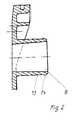
- the required openings 6, 7 and 8 for the oil drain plug (opening 6), the sensor for checking the oil level (opening 7) and for the closure element for the oil filler neck (opening 8) (Fig. 2) are formed during the injection molding .
- a circumferential bead 14 is formed on the end of the oil filler neck 13 pointing outwards, which bead serves as an axial securing aid for the oil filler hose (FIG. 2).
- a channel 9 for cable guides is provided, which is formed by the two projecting side walls 10, 11 and the cover 12 that can be fitted.
Landscapes
- Engineering & Computer Science (AREA)
- Mechanical Engineering (AREA)
- General Engineering & Computer Science (AREA)
- Chemical & Material Sciences (AREA)
- Combustion & Propulsion (AREA)
- Physics & Mathematics (AREA)
- Acoustics & Sound (AREA)
- Lubrication Details And Ventilation Of Internal Combustion Engines (AREA)
- Cylinder Crankcases Of Internal Combustion Engines (AREA)
- Lubricants (AREA)
- Laminated Bodies (AREA)
Applications Claiming Priority (2)
| Application Number | Priority Date | Filing Date | Title |
|---|---|---|---|
| DE29706837U | 1997-04-16 | ||
| DE29706837U DE29706837U1 (de) | 1997-04-16 | 1997-04-16 | Ölwanne für Verbrennungsmotoren |
Publications (2)
| Publication Number | Publication Date |
|---|---|
| EP0872632A1 true EP0872632A1 (fr) | 1998-10-21 |
| EP0872632B1 EP0872632B1 (fr) | 2002-06-19 |
Family
ID=8039060
Family Applications (1)
| Application Number | Title | Priority Date | Filing Date |
|---|---|---|---|
| EP98106436A Expired - Lifetime EP0872632B1 (fr) | 1997-04-16 | 1998-04-08 | Carter d'huile pour moteur à combustion interne |
Country Status (4)
| Country | Link |
|---|---|
| EP (1) | EP0872632B1 (fr) |
| AT (1) | ATE219550T1 (fr) |
| DE (2) | DE29706837U1 (fr) |
| ES (1) | ES2178064T3 (fr) |
Cited By (10)
| Publication number | Priority date | Publication date | Assignee | Title |
|---|---|---|---|---|
| DE19938688A1 (de) * | 1999-08-14 | 2001-02-15 | Volkswagen Ag | Verfahren zum Regeln einer Kühlung von Schmieröl einer Brennkraftmaschine |
| DE10124071A1 (de) * | 2001-05-16 | 2002-12-05 | Joma Polytec Kunststofftechnik | Ölwanne, insbesondere für eine Brennkraftmaschine oder ein Getriebe |
| WO2003016685A1 (fr) * | 2001-08-03 | 2003-02-27 | Dow Global Technologies Inc. | Systeme de carter d'huile fixe de façon adhesive au carter |
| US6543404B2 (en) | 2001-04-04 | 2003-04-08 | Dow Global Technologies, Inc. | Adhesively bonded engine intake manifold assembly |
| EP1741883A1 (fr) * | 2005-06-09 | 2007-01-10 | Mann+Hummel Gmbh | Carter d'huile pour un moteur à combustion interne |
| DE102006002956A1 (de) * | 2006-01-21 | 2007-07-26 | Joma-Polytec Kunststofftechnik Gmbh | Ölwanne für eine Brennkraftmaschine |
| EP2014383A1 (fr) * | 2007-07-13 | 2009-01-14 | MAN Nutzfahrzeuge AG | Cuve et son procédé de fabrication |
| DE102008028442A1 (de) * | 2008-06-17 | 2009-12-24 | Rehau Ag + Co. | Ölwanne für eine Verbrennungskraftmaschine sowie Vorrichtung zur Temperierung des Motorenöls einer Verbrennungskraftmaschine |
| DE102008048793A1 (de) | 2008-09-24 | 2010-03-25 | Mann + Hummel Gmbh | Verfahren zur Herstellung einer Kunststoffölwanne mittels Heißgasschweißen |
| US10808582B2 (en) * | 2016-04-22 | 2020-10-20 | Audi Ag | Drive component for a motor vehicle, and motor vehicle |
Families Citing this family (3)
| Publication number | Priority date | Publication date | Assignee | Title |
|---|---|---|---|---|
| DE19818590C2 (de) | 1998-04-25 | 2000-03-23 | Daimler Chrysler Ag | Ölwanne |
| KR101239033B1 (ko) * | 2011-06-27 | 2013-03-07 | 해양산업 주식회사 | 플라스틱 재질의 오일 팬 |
| KR102540511B1 (ko) * | 2018-03-26 | 2023-06-05 | 현대자동차주식회사 | 자동차용 플라스틱 오일팬의 소음 차단 장치 |
Citations (6)
| Publication number | Priority date | Publication date | Assignee | Title |
|---|---|---|---|---|
| US4223073A (en) * | 1978-10-30 | 1980-09-16 | Minnesota Mining And Manufacturing Company | High-temperature damping composite |
| JPS5749006A (en) * | 1980-09-08 | 1982-03-20 | Toyota Motor Corp | Oil pan for vehicle |
| DE3142327A1 (de) | 1981-10-24 | 1983-05-05 | Dr.Ing.H.C. F. Porsche Ag, 7000 Stuttgart | "oelwanne fuer eine brennkraftmaschine" |
| DE8323945U1 (de) | 1983-08-20 | 1983-12-08 | Karl Joh Gummiwarenfabrik Gmbh, 6460 Gelnhausen | Oelwanne von verbrennungskraftmaschinen, insbesondere von kraftfahrzeugen |
| EP0416297A1 (fr) * | 1989-09-06 | 1991-03-13 | MAN Nutzfahrzeuge Aktiengesellschaft | Carter d'huile en tôle d'insonorisation pour moteur à combustion interne |
| EP0691462A1 (fr) * | 1994-07-07 | 1996-01-10 | Steyr Nutzfahrzeuge Ag | Moteur à combustion interne avec un enveloppe partielle |
Family Cites Families (1)
| Publication number | Priority date | Publication date | Assignee | Title |
|---|---|---|---|---|
| US5452693A (en) * | 1994-12-09 | 1995-09-26 | Cummins Engine Company, Inc. | Oil pan noise enclosure and attachment system for same |
-
1997
- 1997-04-16 DE DE29706837U patent/DE29706837U1/de not_active Expired - Lifetime
-
1998
- 1998-04-08 AT AT98106436T patent/ATE219550T1/de not_active IP Right Cessation
- 1998-04-08 DE DE59804482T patent/DE59804482D1/de not_active Expired - Lifetime
- 1998-04-08 EP EP98106436A patent/EP0872632B1/fr not_active Expired - Lifetime
- 1998-04-08 ES ES98106436T patent/ES2178064T3/es not_active Expired - Lifetime
Patent Citations (6)
| Publication number | Priority date | Publication date | Assignee | Title |
|---|---|---|---|---|
| US4223073A (en) * | 1978-10-30 | 1980-09-16 | Minnesota Mining And Manufacturing Company | High-temperature damping composite |
| JPS5749006A (en) * | 1980-09-08 | 1982-03-20 | Toyota Motor Corp | Oil pan for vehicle |
| DE3142327A1 (de) | 1981-10-24 | 1983-05-05 | Dr.Ing.H.C. F. Porsche Ag, 7000 Stuttgart | "oelwanne fuer eine brennkraftmaschine" |
| DE8323945U1 (de) | 1983-08-20 | 1983-12-08 | Karl Joh Gummiwarenfabrik Gmbh, 6460 Gelnhausen | Oelwanne von verbrennungskraftmaschinen, insbesondere von kraftfahrzeugen |
| EP0416297A1 (fr) * | 1989-09-06 | 1991-03-13 | MAN Nutzfahrzeuge Aktiengesellschaft | Carter d'huile en tôle d'insonorisation pour moteur à combustion interne |
| EP0691462A1 (fr) * | 1994-07-07 | 1996-01-10 | Steyr Nutzfahrzeuge Ag | Moteur à combustion interne avec un enveloppe partielle |
Non-Patent Citations (1)
| Title |
|---|
| PATENT ABSTRACTS OF JAPAN vol. 006, no. 124 (M - 141) 9 July 1982 (1982-07-09) * |
Cited By (12)
| Publication number | Priority date | Publication date | Assignee | Title |
|---|---|---|---|---|
| DE19938688A1 (de) * | 1999-08-14 | 2001-02-15 | Volkswagen Ag | Verfahren zum Regeln einer Kühlung von Schmieröl einer Brennkraftmaschine |
| US6543404B2 (en) | 2001-04-04 | 2003-04-08 | Dow Global Technologies, Inc. | Adhesively bonded engine intake manifold assembly |
| DE10124071A1 (de) * | 2001-05-16 | 2002-12-05 | Joma Polytec Kunststofftechnik | Ölwanne, insbesondere für eine Brennkraftmaschine oder ein Getriebe |
| WO2003016685A1 (fr) * | 2001-08-03 | 2003-02-27 | Dow Global Technologies Inc. | Systeme de carter d'huile fixe de façon adhesive au carter |
| EP1741883A1 (fr) * | 2005-06-09 | 2007-01-10 | Mann+Hummel Gmbh | Carter d'huile pour un moteur à combustion interne |
| US7481196B2 (en) | 2005-06-09 | 2009-01-27 | Mann & Hummel Gmbh | Oil pan useful for an internal combustion engine |
| DE102006002956A1 (de) * | 2006-01-21 | 2007-07-26 | Joma-Polytec Kunststofftechnik Gmbh | Ölwanne für eine Brennkraftmaschine |
| DE102006002956B4 (de) * | 2006-01-21 | 2017-12-28 | Joma-Polytec Gmbh | Ölwanne für eine Brennkraftmaschine |
| EP2014383A1 (fr) * | 2007-07-13 | 2009-01-14 | MAN Nutzfahrzeuge AG | Cuve et son procédé de fabrication |
| DE102008028442A1 (de) * | 2008-06-17 | 2009-12-24 | Rehau Ag + Co. | Ölwanne für eine Verbrennungskraftmaschine sowie Vorrichtung zur Temperierung des Motorenöls einer Verbrennungskraftmaschine |
| DE102008048793A1 (de) | 2008-09-24 | 2010-03-25 | Mann + Hummel Gmbh | Verfahren zur Herstellung einer Kunststoffölwanne mittels Heißgasschweißen |
| US10808582B2 (en) * | 2016-04-22 | 2020-10-20 | Audi Ag | Drive component for a motor vehicle, and motor vehicle |
Also Published As
| Publication number | Publication date |
|---|---|
| ATE219550T1 (de) | 2002-07-15 |
| EP0872632B1 (fr) | 2002-06-19 |
| DE29706837U1 (de) | 1997-07-24 |
| ES2178064T3 (es) | 2002-12-16 |
| DE59804482D1 (de) | 2002-07-25 |
Similar Documents
| Publication | Publication Date | Title |
|---|---|---|
| DE19818590C2 (de) | Ölwanne | |
| EP0872632B1 (fr) | Carter d'huile pour moteur à combustion interne | |
| EP0612944B1 (fr) | Elément de fixation monobloc | |
| DE4327474C2 (de) | Gleitlager für Fahrwerksteile in Kraftfahrzeugen | |
| DE102020104489B4 (de) | Vorrichtung zur Befestigung eines Fahrzeugbauteils in und/oder an einem Fahrzeug | |
| EP0779203B1 (fr) | Couvercle constitué de deux éléments en matière plastique | |
| DE19511479C2 (de) | Verbindungsvorrichtung | |
| DE202008005603U1 (de) | Verbindungsanordnung für luftführende Bauelemente in einem Fahrzeug | |
| DE10332171A1 (de) | Schallisolierendes Gehäuseteil aus Kunststoff für Brennkraftmaschinen oder Fahrzeuggetriebe | |
| DE10060293A1 (de) | Vorrichtung zum Fördern von Kraftstoff aus einem Vorratsbehälter zu einer Brennkraftmaschine | |
| DE4401296C2 (de) | Vorrichtung zur Montage von Automotoren | |
| DE102005033335B4 (de) | Schutzvorrichtung für Leitungen, insbesondere Fluidleitungen, in Kraftfahrzeugen | |
| EP1975490B1 (fr) | Dispositif destiné à maintenir au moins un élément allongé | |
| DE3225929C2 (de) | Kraftstoffbehälter für Brennkraftmaschinen, insbesondere von Kraftfahrzeugen | |
| DE19644359C1 (de) | Schallentkoppelter Gehäusedeckel | |
| DE29822718U1 (de) | Befestigungssystem für Gehäusedeckel an Gehäusen von Kraftmaschinen | |
| DE3942448C2 (fr) | ||
| DE10124621A1 (de) | Betriebsmitteltank | |
| EP1035989B1 (fr) | Dispositif pour loger et maintenir une batterie | |
| DE19606002C2 (de) | Spann- oder Gleitschiene für Kettentriebe von Brennkraftmaschinen | |
| DE19936748B4 (de) | Befestigungssystem für Gehäusedeckel an Gehäusen von Kraftmaschinen | |
| DE20102217U1 (de) | Filter für Flüssigkeiten, insbesondere Kraftstoffe | |
| DE102006019576B4 (de) | Lenkvorrichtung für Fahrzeuge und Verfahren zur Montage einer Lageranordnung | |
| EP1838555A2 (fr) | Element constitutif structural, notamment element de protection | |
| DE602004011103T2 (de) | Motorlagervorrichtung |
Legal Events
| Date | Code | Title | Description |
|---|---|---|---|
| PUAI | Public reference made under article 153(3) epc to a published international application that has entered the european phase |
Free format text: ORIGINAL CODE: 0009012 |
|
| 17P | Request for examination filed |
Effective date: 19980801 |
|
| AK | Designated contracting states |
Kind code of ref document: A1 Designated state(s): AT CH DE ES FR GB IT LI SE |
|
| AX | Request for extension of the european patent |
Free format text: AL;LT;LV;MK;RO;SI |
|
| AKX | Designation fees paid |
Free format text: AT CH DE ES FR GB IT LI SE |
|
| RAP1 | Party data changed (applicant data changed or rights of an application transferred) |
Owner name: KUNSTSTOFFTECHNIK RIESSELMANN GMBH & CO. KG |
|
| 17Q | First examination report despatched |
Effective date: 20010309 |
|
| GRAG | Despatch of communication of intention to grant |
Free format text: ORIGINAL CODE: EPIDOS AGRA |
|
| GRAG | Despatch of communication of intention to grant |
Free format text: ORIGINAL CODE: EPIDOS AGRA |
|
| GRAH | Despatch of communication of intention to grant a patent |
Free format text: ORIGINAL CODE: EPIDOS IGRA |
|
| GRAH | Despatch of communication of intention to grant a patent |
Free format text: ORIGINAL CODE: EPIDOS IGRA |
|
| GRAA | (expected) grant |
Free format text: ORIGINAL CODE: 0009210 |
|
| AK | Designated contracting states |
Kind code of ref document: B1 Designated state(s): AT CH DE ES FR GB IT LI SE |
|
| REF | Corresponds to: |
Ref document number: 219550 Country of ref document: AT Date of ref document: 20020715 Kind code of ref document: T |
|
| REG | Reference to a national code |
Ref country code: GB Ref legal event code: FG4D Free format text: NOT ENGLISH |
|
| REG | Reference to a national code |
Ref country code: CH Ref legal event code: EP |
|
| REF | Corresponds to: |
Ref document number: 59804482 Country of ref document: DE Date of ref document: 20020725 |
|
| REG | Reference to a national code |
Ref country code: CH Ref legal event code: NV Representative=s name: SCHMAUDER & PARTNER AG PATENTANWALTSBUERO |
|
| GBT | Gb: translation of ep patent filed (gb section 77(6)(a)/1977) |
Effective date: 20020816 |
|
| ET | Fr: translation filed | ||
| REG | Reference to a national code |
Ref country code: ES Ref legal event code: FG2A Ref document number: 2178064 Country of ref document: ES Kind code of ref document: T3 |
|
| PLBE | No opposition filed within time limit |
Free format text: ORIGINAL CODE: 0009261 |
|
| STAA | Information on the status of an ep patent application or granted ep patent |
Free format text: STATUS: NO OPPOSITION FILED WITHIN TIME LIMIT |
|
| PG25 | Lapsed in a contracting state [announced via postgrant information from national office to epo] |
Ref country code: LI Free format text: LAPSE BECAUSE OF NON-PAYMENT OF DUE FEES Effective date: 20030430 Ref country code: CH Free format text: LAPSE BECAUSE OF NON-PAYMENT OF DUE FEES Effective date: 20030430 |
|
| 26N | No opposition filed |
Effective date: 20030320 |
|
| REG | Reference to a national code |
Ref country code: CH Ref legal event code: PL |
|
| REG | Reference to a national code |
Ref country code: GB Ref legal event code: 732E |
|
| REG | Reference to a national code |
Ref country code: FR Ref legal event code: TP |
|
| PGFP | Annual fee paid to national office [announced via postgrant information from national office to epo] |
Ref country code: ES Payment date: 20080424 Year of fee payment: 11 |
|
| PGFP | Annual fee paid to national office [announced via postgrant information from national office to epo] |
Ref country code: AT Payment date: 20080423 Year of fee payment: 11 |
|
| PGFP | Annual fee paid to national office [announced via postgrant information from national office to epo] |
Ref country code: IT Payment date: 20080426 Year of fee payment: 11 |
|
| PGFP | Annual fee paid to national office [announced via postgrant information from national office to epo] |
Ref country code: SE Payment date: 20080424 Year of fee payment: 11 |
|
| PGFP | Annual fee paid to national office [announced via postgrant information from national office to epo] |
Ref country code: FR Payment date: 20080418 Year of fee payment: 11 |
|
| PGFP | Annual fee paid to national office [announced via postgrant information from national office to epo] |
Ref country code: GB Payment date: 20080423 Year of fee payment: 11 |
|
| EUG | Se: european patent has lapsed | ||
| GBPC | Gb: european patent ceased through non-payment of renewal fee |
Effective date: 20090408 |
|
| REG | Reference to a national code |
Ref country code: FR Ref legal event code: ST Effective date: 20091231 |
|
| PG25 | Lapsed in a contracting state [announced via postgrant information from national office to epo] |
Ref country code: AT Free format text: LAPSE BECAUSE OF NON-PAYMENT OF DUE FEES Effective date: 20090408 |
|
| PG25 | Lapsed in a contracting state [announced via postgrant information from national office to epo] |
Ref country code: GB Free format text: LAPSE BECAUSE OF NON-PAYMENT OF DUE FEES Effective date: 20090408 Ref country code: FR Free format text: LAPSE BECAUSE OF NON-PAYMENT OF DUE FEES Effective date: 20091222 |
|
| REG | Reference to a national code |
Ref country code: ES Ref legal event code: FD2A Effective date: 20090411 |
|
| PG25 | Lapsed in a contracting state [announced via postgrant information from national office to epo] |
Ref country code: ES Free format text: LAPSE BECAUSE OF NON-PAYMENT OF DUE FEES Effective date: 20090411 |
|
| PG25 | Lapsed in a contracting state [announced via postgrant information from national office to epo] |
Ref country code: IT Free format text: LAPSE BECAUSE OF NON-PAYMENT OF DUE FEES Effective date: 20090408 |
|
| PG25 | Lapsed in a contracting state [announced via postgrant information from national office to epo] |
Ref country code: SE Free format text: LAPSE BECAUSE OF NON-PAYMENT OF DUE FEES Effective date: 20090409 |
|
| REG | Reference to a national code |
Ref country code: DE Ref legal event code: R082 Ref document number: 59804482 Country of ref document: DE Representative=s name: WEIDNER STERN JESCHKE PATENTANWAELTE PARTNERSC, DE |
|
| PGFP | Annual fee paid to national office [announced via postgrant information from national office to epo] |
Ref country code: DE Payment date: 20170428 Year of fee payment: 20 |
|
| REG | Reference to a national code |
Ref country code: DE Ref legal event code: R071 Ref document number: 59804482 Country of ref document: DE |