EP0872852A2 - Universales Kabelabwickelsystem - Google Patents
Universales Kabelabwickelsystem Download PDFInfo
- Publication number
- EP0872852A2 EP0872852A2 EP98200782A EP98200782A EP0872852A2 EP 0872852 A2 EP0872852 A2 EP 0872852A2 EP 98200782 A EP98200782 A EP 98200782A EP 98200782 A EP98200782 A EP 98200782A EP 0872852 A2 EP0872852 A2 EP 0872852A2
- Authority
- EP
- European Patent Office
- Prior art keywords
- cable
- barrel
- sub
- pack
- processing machine
- Prior art date
- Legal status (The legal status is an assumption and is not a legal conclusion. Google has not performed a legal analysis and makes no representation as to the accuracy of the status listed.)
- Withdrawn
Links
Images


Classifications
-
- B—PERFORMING OPERATIONS; TRANSPORTING
- B65—CONVEYING; PACKING; STORING; HANDLING THIN OR FILAMENTARY MATERIAL
- B65H—HANDLING THIN OR FILAMENTARY MATERIAL, e.g. SHEETS, WEBS, CABLES
- B65H49/00—Unwinding or paying-out filamentary material; Supporting, storing or transporting packages from which filamentary material is to be withdrawn or paid-out
- B65H49/02—Methods or apparatus in which packages do not rotate
- B65H49/04—Package-supporting devices
- B65H49/06—Package-supporting devices for a single operative package
- B65H49/08—Package-supporting devices for a single operative package enclosing the package
-
- B—PERFORMING OPERATIONS; TRANSPORTING
- B21—MECHANICAL METAL-WORKING WITHOUT ESSENTIALLY REMOVING MATERIAL; PUNCHING METAL
- B21C—MANUFACTURE OF METAL SHEETS, WIRE, RODS, TUBES, PROFILES OR LIKE SEMI-MANUFACTURED PRODUCTS OTHERWISE THAN BY ROLLING; AUXILIARY OPERATIONS USED IN CONNECTION WITH METAL-WORKING WITHOUT ESSENTIALLY REMOVING MATERIAL
- B21C47/00—Winding-up, coiling or winding-off metal wire, metal band or other flexible metal material characterised by features relevant to metal processing only
- B21C47/16—Unwinding or uncoiling
- B21C47/18—Unwinding or uncoiling from reels or drums
- B21C47/20—Unwinding or uncoiling from reels or drums the unreeled material moving transversely to the tangent line of the drum, e.g. axially, radially
-
- B—PERFORMING OPERATIONS; TRANSPORTING
- B65—CONVEYING; PACKING; STORING; HANDLING THIN OR FILAMENTARY MATERIAL
- B65H—HANDLING THIN OR FILAMENTARY MATERIAL, e.g. SHEETS, WEBS, CABLES
- B65H49/00—Unwinding or paying-out filamentary material; Supporting, storing or transporting packages from which filamentary material is to be withdrawn or paid-out
- B65H49/02—Methods or apparatus in which packages do not rotate
-
- B—PERFORMING OPERATIONS; TRANSPORTING
- B65—CONVEYING; PACKING; STORING; HANDLING THIN OR FILAMENTARY MATERIAL
- B65H—HANDLING THIN OR FILAMENTARY MATERIAL, e.g. SHEETS, WEBS, CABLES
- B65H57/00—Guides for filamentary materials; Supports therefor
- B65H57/22—Guides for filamentary materials; Supports therefor adapted to prevent excessive ballooning of material
-
- B—PERFORMING OPERATIONS; TRANSPORTING
- B65—CONVEYING; PACKING; STORING; HANDLING THIN OR FILAMENTARY MATERIAL
- B65H—HANDLING THIN OR FILAMENTARY MATERIAL, e.g. SHEETS, WEBS, CABLES
- B65H59/00—Adjusting or controlling tension in filamentary material, e.g. for preventing snarling; Applications of tension indicators
- B65H59/02—Adjusting or controlling tension in filamentary material, e.g. for preventing snarling; Applications of tension indicators by regulating delivery of material from supply package
- B65H59/06—Adjusting or controlling tension in filamentary material, e.g. for preventing snarling; Applications of tension indicators by regulating delivery of material from supply package by devices acting on material leaving the package
-
- B—PERFORMING OPERATIONS; TRANSPORTING
- B65—CONVEYING; PACKING; STORING; HANDLING THIN OR FILAMENTARY MATERIAL
- B65H—HANDLING THIN OR FILAMENTARY MATERIAL, e.g. SHEETS, WEBS, CABLES
- B65H59/00—Adjusting or controlling tension in filamentary material, e.g. for preventing snarling; Applications of tension indicators
- B65H59/10—Adjusting or controlling tension in filamentary material, e.g. for preventing snarling; Applications of tension indicators by devices acting on running material and not associated with supply or take-up devices
- B65H59/16—Braked elements rotated by material
Definitions
- This invention relates to a method and equipment for processing wire cable.
- Wire cable can be utilized to making wire harness assemblies.
- the wire must first be coated with an electrical insulation material, and thereafter post coating operations performed before it can be utilized in making wire harness assemblies.
- the cable is typically wound onto spools or into cable packs such as barrels. Barrels are a preferred method of shipping the cable because the barrel protects the outer windings of the cable from damage during shipment. Further, barrels with a core are more preferred because they also prevent the cable from shifting and becoming entangled during shipment. After the cable has been wound into a barrel, the barrels are placed into a truck and shipped a long distance to a processing facility to perform subsequent operations.
- the cable wire is then fed into an automatic cable processing machine.
- the automatic cable processing machine pulls the cable out of the barrel and into the machine at predetermined lengths.
- the machine stops pulling the cable, cuts, terminates and crimps the ends of the cable for use in wire harness assemblies.
- the cable often became entangled, knotted or snapped during the repetitive pull-stop action of the automatic cable processing machines.
- the present invention provides advantages over and alternatives to the prior art.
- the present invention includes a sub-system for controlling the flow of cable pulled from a cable pack such as a barrel by an automatic cable processing machine.
- the sub-system may include a barrel cap for containing and controlling the outward momentum of the cable over the barrel and guiding the cable through a passage in the top of the cap. The passage is positioned in line with a center line of the barrel.
- a variable rate braking system may be positioned over the barrel and adjacent an outer wall of the barrel to control the circular movement of the cable as the cable is unwound from the barrel.
- a spacer may be positioned to prevent the cable from being pulled towards the center of the barrel or toward the barrel core and so that the cable engages the variable rate braking system. The system prevents cable from overlapping, entangling, knotting and snapping during the automatic processing of the cable for use in wire harnesses.
- a conical shaped cap is provided to control the cables outward momentum.
- the rim of the conical shaped cap is lined with inwardly facing brushes having a free end nearest the center line of the cap to control the circular movement of the cable and to provide a variable rate braking action.
- a barrel disk is provided over the center of the barrel to keep the cable within the brushes while ensuring that the cable is pulled away from the center of the barrel, and particularly away from the core of the barrel.
- a continuous tensioning device is provided having two counter rotating belts. The belt surfaces move with the cable as the cable is pulled through by the automatic cable processing machine. The counter rotating belts minimize friction, reduce the potential for insulation damage and do not add memory characteristics to the cable. This results in straighter cable entering the automatic cable processing machine.
- the belt tension ratio allows the cable to move through the belts as the processing machine pulls the cable but also exhibits the appropriate braking action to stop the cables momentum when the pulling operation of the cable processing machine is stopped.
- An alignment device is provided for mounting the sub-system to the automatic cable processing machine and to eliminate any damage associated with misalignment.
- FIG. 1 A preferred embodiment of the present invention is illustrated in Figures 1 and 2.
- the five main features of this embodiment are integrated into a sub-system 10 that controls the wire cable 12 as it is pulled from a cable pack such as a barrel 14.
- the sub-system 10 includes a cap 16 overlying a barrel 14 and is constructed and arranged to guide the cable 12 and control the cables 12 outward momentum above the barrel as the cable is rapidly pulled by the automatic cable processing machine.
- the sub-system includes a variable rate braking system 18 to control the circular momentum of the cable 12.
- a spacer 20 is provided to keep the cable within the variable rate braking system 18 and to insure that the cable is pulled away from the center of the barrel 14 and particularly away from the core 24 of the barrel.
- the system includes a rotating tensioning system 22 to control the movement of the cable and to prevent potential damage to the cable insulation.
- the sub-system includes an alignment system 26 for directing the cable and properly mounting the sub-system to the automatic cable processing machine. Details of each of the five main features of the preferred embodiment and the equipment it is intended to be useful with will now be described.
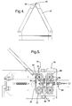
- the sub-system of the present invention is useful in controlling the flow of cable pulled by an automatic cable processing machine as schematically illustrated by Figure 7.
- the sub-system is useful with a variety of different cable packs such as a bag, box, spool and the like having cable wound on or therein.
- the cable pack is a barrel 14 having a generally cylindrical outer wall 28 and a tapered central core 24 around which the cable 12 has been wrapped ( Figures 1, 2 and 6).
- the barrel 14 may include wheels 30 attached to a lower end or may be provided ion any device for easy movement of the barrel around the processing facility.
- variable rate braking system 18 is provided adjacent the outer wall 28 of the barrel.
- the variable rate braking system includes two inwardly facing, curved arced or semi-circular shaped brushes 32 to control the circular momentum of the cable.
- the brushes 32 each have bristles 34 including a first end fixed 36 to an arc shaped or a semi-circular base 38 which can be received in a slot 40 formed in one of the cone shaped cap halves 46, 48.
- the brush bristles 34 each have a second end 42 which is free to move and extends inwardly towards the center of the barrel.
- the brushes 32 provide a variable rate braking action as the cable is pulled from the barrel.
- the cable When the cable is pulled from the barrel, the cable tends to move towards the center of the barrel and towards the free end 42 of the brush bristles.
- the cable moves in a circular pattern as the cable is being unwounded from the barrel, and the free end 42 of the brush subjects the cable to very little resistance or breaking action.
- the machine stops pulling the cable.
- the cable still has a circular and an outward momentum which forces the cable toward the fixed end 36 of the brush bristles which supplies a substantial amount of resistance or braking action to the cable and stops the cable almost immediately.
- the brush 32 with a free end 42 of the bristle extending inwardly towards the barrel provides a variable rate braking action by supplying very little resistance to movement of the cable as the cable begins to be pulled out of the barrel, and the fixed end 36 of the bristle applies a substantial amount of resistance or braking action as the cable processing machine stops pulling cable from the barrel.
- the fixed end 36 of the bristle applies a substantial amount of resistance or braking action as the cable processing machine stops pulling cable from the barrel.
- Immediately stopping the cable from moving when the machine stops pulling prevents the cable from overlapping and becoming entangled in the barrel. If the cable becomes entangled in the barrel, the cable will be snapped the next time the machine begins to pull cable. Consequently, an operator must thread the cable into the machine again which results in a substantial amount of down time.
- the preferred embodiment also includes a spacer 20 which may be a disk placed over the barrel 14 and constructed and arranged to prevent the cable from moving towards the center of the barrel.
- the spacer 20 keeps the cable near the free end 42 of the brushes to insure that the cable is properly controlled by the variable rate braking system.
- the spacer 20 extends up to the free end 42 of the brush bristle and more preferably under the free end 42 to insure that the cable always engages the brush.
- the spacer may be a variety of shapes such as disk shaped and clipped the core 24 of the barrel or may be ring shaped and place on top or over the upper portion of the tapered barrel core 24.
- the cap 16 may have any of a variety of configurations sufficient to control the outward momentum of the cable and limit the cables tendency to arc outwardly above the barrel as the cable is rapidly pulled from the barrel. Suitable configurations of the cap may include vaulted or domed shapes, or more preferably a cone shape as illustrated in Figures 1 and 2.
- the cable tends to arc outwardly above the barrel due to the centrifugal force and outward momentum caused by the rapid pulling of the cable by the processing machine. If left unrestricted, the arcing cable may get caught on process equipment or the momentum may cause the cable to overlap other windings and become entangled when the machine stops pulling. However, the cap physically restrains the arcing and outward momentum or movement of the cable.
- the cone shaped cap is a two piece structure with a first half 46 secured to a flange 50 on the alignment system 26.
- the second half 48 of the cone shaped cap is removable from the first half 46.
- Quick release lock mechanisms 52 are provided to removably secure the two halves of the cone shaped cap.
- Handles 54 may be provided to assist in the easy removal of one of the cap halves. With one of the cap halves 48 removed, for the barrel 14 is rolled into and received by the other cap half 46. The second cap half 48 is then secured to the first cap half 46 to enclose an upper portion of the barrel 14. Naturally, a single piece cap can be lowered over the barrel.
- the cap 16 has a hole or passage 56 formed near the top of the cap and positioned substantially in line within a center line of the barrel 14.
- a funnel shaped guide member 58 is positioned to guide the cable through the hole formed in the cap so that the cable does not engage any sharp edges which would damage the insulative (insulation) coating on the cable.
- the sub-system also includes an alignment device 26 that is firmly secured to the automatic cable processing machine 60 so that the sub-system is held in place.
- the alignment device 26 may have a variety of configurations but preferably includes a base 62 and a vertically extending arm 64 secured to the base.
- An adjustable bracket 66 extends horizontally from the vertical arm 64 to secure the sub-system to the automatic cable processing machine 60.
- a second arm 68 is secured at an angle to the top of the vertical arm.
- a continuous tensioning device 22 is secured to the second arm and extends downwardly toward the top of the cone shaped cap.
- the cable is fed through the funnel 58 and passage 56 in the cap 16, through the continuous tensioning device 22, over a first roller or pulley 70 on the second arm 68, under a second roller or pulley 72 on the vertical arm 64 so that the cable can be fed in a horizontal direction into the automatic cable processing machine 60.
- the alignment device 26 preferably is constructed from adjustable arms 64, 68 and bracket 66 so that the device can be easily modified to accommodate a variety of automatic cable processing machines that are currently on the market or future designs.
- the continuous tensioning device 22 includes counter rotating brake members 74, 76 for applying a constant tension to the cable 12 as it is pulled into the automatic cable processing machine.
- Rotating brake members are preferred over stationary braking elements which may cause damage to the cable insulation or cause bending or kinking of the cable.
- the rotating brake members 74, 76 including a first braking element 74 having a plurality of bearing loaded rollers 78 secured to a stationary substrate 78.
- a belt 82 rides on the bearing loaded rollers 78.
- the belt 82 and rollers 78 have mating teeth 84, 86 respectively to prevent the belt from slipping over the rollers.
- a second rotating brake member 76 is similarly constructed but the bearing loaded rollers 78 are secured to a movable substrate 88 which is biased towards the first rotating brake member 74 by a spring 90.
- a lever arm 92 connected to a cam may be provided to allow the two rotating brake members 74, 76 to be easily held apart to facilitate stringing the cable through the constant tensioning device 22.
- the belts 82 rotate in opposite directions so that the cable 12 and belts 82 are moving in unison up through the tensioning device in the direction of the arrow shown in Figure 5. This is important because the counter direction moving belts 82 provide an almost immediate stopping action without damaging the cable insulation or adding any memory characteristics to the cable so that a straighter cable is presented to the automatic cable processing machine.
- cable includes bare wire or wire coated with an insulation or wire with other improvements.
Landscapes
- Engineering & Computer Science (AREA)
- Mechanical Engineering (AREA)
- Tension Adjustment In Filamentary Materials (AREA)
- Packaging Of Machine Parts And Wound Products (AREA)
- Unwinding Of Filamentary Materials (AREA)
- Storage Of Web-Like Or Filamentary Materials (AREA)
Applications Claiming Priority (2)
| Application Number | Priority Date | Filing Date | Title |
|---|---|---|---|
| US837510 | 1997-04-14 | ||
| US08/837,510 US5806780A (en) | 1997-04-14 | 1997-04-14 | Universal cable take-off system |
Publications (2)
| Publication Number | Publication Date |
|---|---|
| EP0872852A2 true EP0872852A2 (de) | 1998-10-21 |
| EP0872852A3 EP0872852A3 (de) | 1999-09-01 |
Family
ID=25274661
Family Applications (1)
| Application Number | Title | Priority Date | Filing Date |
|---|---|---|---|
| EP98200782A Withdrawn EP0872852A3 (de) | 1997-04-14 | 1998-03-12 | Universales Kabelabwickelsystem |
Country Status (3)
| Country | Link |
|---|---|
| US (1) | US5806780A (de) |
| EP (1) | EP0872852A3 (de) |
| JP (1) | JPH10291729A (de) |
Cited By (1)
| Publication number | Priority date | Publication date | Assignee | Title |
|---|---|---|---|---|
| ES2178521A1 (es) * | 1999-07-02 | 2002-12-16 | Inoxfil S A | Mecanismo para devanado de un rollo alambrico alojado en un envase. |
Families Citing this family (11)
| Publication number | Priority date | Publication date | Assignee | Title |
|---|---|---|---|---|
| AU752478B2 (en) * | 1998-12-16 | 2002-09-19 | Lincoln Global, Inc. | A method and apparatus for packing wire in a storage drum |
| US6019303A (en) * | 1998-12-16 | 2000-02-01 | Lincoln Global, Inc. | Method and apparatus for packing wire in a storage drum |
| SE518955C2 (sv) * | 2001-05-17 | 2002-12-10 | Metso Paper Inc | Anordning och sätt att haspla av tråd från en trådspole |
| US7441721B2 (en) * | 2002-06-17 | 2008-10-28 | Hyundai Welding Co., Ltd. | Device for preventing welding wire from tangling |
| US7004419B2 (en) * | 2003-07-30 | 2006-02-28 | Lincoln Global, Inc. | Apparatus for packing wire in a storage container by use of reverse winding |
| US7429031B1 (en) | 2005-12-20 | 2008-09-30 | Zephyr International Llc | Ground support system |
| US8678186B2 (en) * | 2006-11-09 | 2014-03-25 | Lincoln Global, Inc. | Wire payoff brush and container containing a wire payoff brush |
| US7938352B2 (en) * | 2009-03-10 | 2011-05-10 | Lincoln Global, Inc. | Wire dispensing apparatus for packaged wire |
| SE534408C2 (sv) * | 2009-11-25 | 2011-08-09 | Metso Paper Inc | Anordning och förfarande för avlindning av tråd från en spole |
| WO2022047013A1 (en) * | 2020-08-27 | 2022-03-03 | American Linc, Llc | Canister-yarn tensioning assembly incorporating a pivoted yarn tensioner |
| US12606409B1 (en) * | 2020-12-23 | 2026-04-21 | A.B. Carter, Inc. | Canister-yarn tensioning assembly incorporating a pivoted yarn tensioner |
Family Cites Families (20)
| Publication number | Priority date | Publication date | Assignee | Title |
|---|---|---|---|---|
| US2864565A (en) * | 1955-03-07 | 1958-12-16 | Rea Magnet Wire Company Inc | Apparatus for dispensing wire |
| US2838922A (en) * | 1955-09-07 | 1958-06-17 | Rosedale Knitting Company | Yarn control device |
| US3203642A (en) * | 1963-05-20 | 1965-08-31 | Donald A Hirst | Wire dereeling equiopment |
| IT956498B (it) * | 1972-06-13 | 1973-10-10 | Pirelli | Apparecchiatura per lo svolgimento di filo raccolto in un fusto nella fabbricazione di cavi elettrici |
| US3879978A (en) * | 1974-01-07 | 1975-04-29 | Reynolds Metals Co | Wire unreeling system |
| US3995786A (en) * | 1975-01-15 | 1976-12-07 | Wesco Industries Corporation | Intermediate yarn feeding and control device |
| US3995758A (en) * | 1975-03-31 | 1976-12-07 | Kovaleski Joseph J | Spool-handling dolly |
| US4171783A (en) * | 1978-05-12 | 1979-10-23 | Phelps Dodge Industries, Inc. | Filament dereeling apparatus |
| US4186897A (en) * | 1978-07-31 | 1980-02-05 | Brown Maurice H | Wire control mechanism |
| FR2456064A1 (fr) * | 1979-05-09 | 1980-12-05 | Bonnabaud Marcel | Dispositif de devidage de fils a la defilee |
| US4222535A (en) * | 1979-07-16 | 1980-09-16 | Mossberg Hubbard, Division Of Wanskuck Company | Wire dereeling apparatus |
| US4508290A (en) * | 1984-02-06 | 1985-04-02 | Wyrepak Industries, Inc. | Cap assembly with friction drag on tension brush |
| SU1320154A1 (ru) * | 1985-11-11 | 1987-06-30 | Центральный научно-исследовательский институт хлопчатобумажной промышленности | Устройство дл нат жени нитевидного материала |
| SU1391759A1 (ru) * | 1986-05-27 | 1988-04-30 | Всесоюзный научно-исследовательский институт гелиевой техники | Устройство дл нат жени длинномерного материала |
| US4754937A (en) * | 1987-10-23 | 1988-07-05 | Clipper Machines, Inc. | Wire payoff apparatus |
| US5040741A (en) * | 1990-05-09 | 1991-08-20 | Brown Maurice H | Method and apparatus for establishing and maintaining a selected tension on uncoiling wire |
| DE3914754C1 (en) * | 1989-05-05 | 1990-10-25 | Hermann Schleicher Gmbh & Co Maschinenfabrik, 8520 Erlangen, De | Brake frame for tensioning metal strips - includes lower than atmospheric pressure chamber at entrance to area where strip is tensioned between endless belts |
| FR2661118B1 (fr) * | 1990-04-20 | 1993-08-27 | Rozenblit Sa | Procede et dispositif pour devider une bobine de fil metallique et machines de fabrication de ressorts en fil metallique. |
| DE4105981C2 (de) * | 1991-02-26 | 1999-08-19 | Sipra Patent Beteiligung | Fadenliefervorrichtung |
| CA2071419C (en) * | 1991-06-18 | 1996-03-19 | William Dimmett Cooper | Retainer ring for welding wire container |
-
1997
- 1997-04-14 US US08/837,510 patent/US5806780A/en not_active Expired - Fee Related
-
1998
- 1998-03-12 EP EP98200782A patent/EP0872852A3/de not_active Withdrawn
- 1998-04-14 JP JP10102566A patent/JPH10291729A/ja active Pending
Cited By (1)
| Publication number | Priority date | Publication date | Assignee | Title |
|---|---|---|---|---|
| ES2178521A1 (es) * | 1999-07-02 | 2002-12-16 | Inoxfil S A | Mecanismo para devanado de un rollo alambrico alojado en un envase. |
Also Published As
| Publication number | Publication date |
|---|---|
| EP0872852A3 (de) | 1999-09-01 |
| JPH10291729A (ja) | 1998-11-04 |
| US5806780A (en) | 1998-09-15 |
Similar Documents
| Publication | Publication Date | Title |
|---|---|---|
| CN110800072B (zh) | 利用条带来缠绕线束 | |
| US5806780A (en) | Universal cable take-off system | |
| EP0296860B1 (de) | Faseraufspulvorrichtung | |
| US7124980B2 (en) | Wire spool guide assembly | |
| RS57815B1 (sr) | Uređaj za uvlačenje niti na držaču kalemova i postupak za njegovu upotrebu | |
| EP2870096B1 (de) | Transport von einem länglichen element von einer rolle zu einer anderen rolle | |
| US20200207571A1 (en) | Method and system for feeding a twisted braided metal cable or flat wire from a corresponding support without altering the structure or shape of the wire | |
| CA1247500A (en) | Wire coil package | |
| JP4345939B2 (ja) | トロイダルコアの自動巻線装置 | |
| CN108988102B (zh) | 用于加工线缆的方法和装置 | |
| US20070018031A1 (en) | Wire cable dispenser | |
| US5465916A (en) | Winding up at least one synthetic-resin yarn | |
| US2963240A (en) | Apparatus for unreeling wire | |
| US2673046A (en) | Apparatus for uncoiling wire | |
| US2390158A (en) | Reel for wire-drawing machines | |
| KR101858415B1 (ko) | 와이어 코팅장치 | |
| US3763899A (en) | Wire twisting device | |
| US4552320A (en) | Method and apparatus for forming snarl-free thread reserves | |
| EP1181229B1 (de) | Verfahren und vorrichtung zum wickeln einer rolle kabeldraht, seil oder dergleichen | |
| JP2879669B2 (ja) | ケーブル先導案内装置 | |
| US4036450A (en) | Method and apparatus for paying out wire | |
| JP2025077153A (ja) | ボビンでの金属線材自動結束装置および方法 | |
| EP0186437A2 (de) | Verseilmaschine | |
| KR102803315B1 (ko) | 전선 이탈방지수단을 갖는 풀링 장치 | |
| US2353645A (en) | Fastening forming machine |
Legal Events
| Date | Code | Title | Description |
|---|---|---|---|
| PUAI | Public reference made under article 153(3) epc to a published international application that has entered the european phase |
Free format text: ORIGINAL CODE: 0009012 |
|
| AK | Designated contracting states |
Kind code of ref document: A2 Designated state(s): DE FR GB IT |
|
| AX | Request for extension of the european patent |
Free format text: AL;LT;LV;MK;RO;SI |
|
| PUAL | Search report despatched |
Free format text: ORIGINAL CODE: 0009013 |
|
| AK | Designated contracting states |
Kind code of ref document: A3 Designated state(s): AT BE CH DE DK ES FI FR GB GR IE IT LI LU MC NL PT SE |
|
| AX | Request for extension of the european patent |
Free format text: AL;LT;LV;MK;RO;SI |
|
| 17P | Request for examination filed |
Effective date: 20000301 |
|
| AKX | Designation fees paid |
Free format text: DE FR GB IT |
|
| RAP1 | Party data changed (applicant data changed or rights of an application transferred) |
Owner name: DELPHI TECHNOLOGIES, INC. |
|
| STAA | Information on the status of an ep patent application or granted ep patent |
Free format text: STATUS: THE APPLICATION IS DEEMED TO BE WITHDRAWN |
|
| 18D | Application deemed to be withdrawn |
Effective date: 20011002 |