EP0873249B1 - Einstellbare abstützvorrichtung für ein kinderfahrzeug - Google Patents
Einstellbare abstützvorrichtung für ein kinderfahrzeug Download PDFInfo
- Publication number
- EP0873249B1 EP0873249B1 EP97901430A EP97901430A EP0873249B1 EP 0873249 B1 EP0873249 B1 EP 0873249B1 EP 97901430 A EP97901430 A EP 97901430A EP 97901430 A EP97901430 A EP 97901430A EP 0873249 B1 EP0873249 B1 EP 0873249B1
- Authority
- EP
- European Patent Office
- Prior art keywords
- tongue
- wheel
- mounting assembly
- vehicle
- Prior art date
- Legal status (The legal status is an assumption and is not a legal conclusion. Google has not performed a legal analysis and makes no representation as to the accuracy of the status listed.)
- Expired - Lifetime
Links
- 239000002991 molded plastic Substances 0.000 claims description 2
- 238000004519 manufacturing process Methods 0.000 description 5
- 230000000712 assembly Effects 0.000 description 2
- 238000000429 assembly Methods 0.000 description 2
- 239000004033 plastic Substances 0.000 description 2
- 241000270281 Coluber constrictor Species 0.000 description 1
- OQZCSNDVOWYALR-UHFFFAOYSA-N flurochloridone Chemical compound FC(F)(F)C1=CC=CC(N2C(C(Cl)C(CCl)C2)=O)=C1 OQZCSNDVOWYALR-UHFFFAOYSA-N 0.000 description 1
- 230000013011 mating Effects 0.000 description 1
- 239000002184 metal Substances 0.000 description 1
- 238000000034 method Methods 0.000 description 1
- 238000012986 modification Methods 0.000 description 1
- 230000004048 modification Effects 0.000 description 1
- 239000004576 sand Substances 0.000 description 1
- 201000009032 substance abuse Diseases 0.000 description 1
Images


Classifications
-
- B—PERFORMING OPERATIONS; TRANSPORTING
- B60—VEHICLES IN GENERAL
- B60B—VEHICLE WHEELS; CASTORS; AXLES FOR WHEELS OR CASTORS; INCREASING WHEEL ADHESION
- B60B37/00—Wheel-axle combinations, e.g. wheel sets
- B60B37/10—Wheel-axle combinations, e.g. wheel sets the wheels being individually rotatable around the axles
Definitions
- the present invention relates to children's ride-on vehicles, and more particularly to a wheel-mounting assembly for use on such a vehicle to accommodate different-sized wheels and provide easy assembly.
- Vehicles for children between the ages of 3-7 years who weigh up to 59kg (130 lbs) include the Jeep® Sand Blaster ®; vehicles designed for children between the ages of 3-7 years who weigh up to 29.5 kg (65 lbs) include the Suzuki® Quad Racer® 900; and, vehicles designed for children between the ages of 1 ⁇ 2 -6 years who weigh up to 22.7 kg (50 lbs) include the Lil Sand Blaster®, to name a few.
- US 4850929 discloses a hand-held children's toy with pivotal axles 2 that enable a child to position the axle in a range of temporary positions with respect to the body of the toy.
- US 4,709,958 discloses a children's ride-on vehicle 11 and a method of assembling front 13 and rear 14 body portions on the vehicle.
- US 4,573,941 discloses a hand held children's toy with a handle bar 16 attached to a steering post 15 that makes it possible for a child to steer the hand held toy.
- One more object of the present invention is to provide an assembly that achieves the above results and yet is economical to manufacture by virtue of having relatively few parts and is readily moldable from plastic.
- An additional object of the invention is to provide a wheel-mounting assembly that does not require precisely manufactured parts and is easily attached to the rest of the vehicle.
- Yet another object of the invention is to provide a structure that is rugged enough to tolerate the abuses expected in the operating environment.
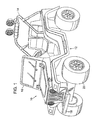
- a ride-on vehicle constructed according to the present invention is shown generally at 10 in Fig. 1.
- the grille depicted on the front of the vehicle in Fig. 1 is a registered trademark of Chrysler Corporation.
- Vehicle 10 includes a body member 12 which is preferably formed as a unitary structure from molded plastic.
- body 12 which is preferably formed as a unitary structure from molded plastic.
- Various accessories are attached to body 12, such as roll bar 14, windshield 16, bumper 18 and wheels 20. It should be noted that positional references in the following description will be made assuming that the vehicle is in an upright position.
- a cavity 22 is formed in the front region of body 12.
- Cavity 22 projects downwardly from the surrounding body and includes a flat bottom 24 and walls 25 defining a perimeter of the cavity.
- a box-like hollow alignment tongue 26 extends downwardly from the bottom of the cavity.
- Tongue 26 includes an outer surface 28 which tapers from a large rectangular cross-section at a base 30 adjacent bottom 24 to a smaller rectangular cross-section at a tip 32.
- the outside dimensions of the cross-section of the tongue in the preferred embodiment are approximately 152 mm x 51 mm (6 x 2 inches) at the tip, and 178 mm x 51 mm (7 x 2 inches) at the base, with the tongue being approximately 51 mm (2 inches) long.
- This geometry corresponds to a taper angle of approximately 5-degrees for each side of the tongue, although taper angles between 2- and 30-degrees would probably be suitable. It is expected that the dimensions of the cross-section of the tongue at the base could be anywhere between 25 x 102 mm (1 x 4 inches) and 203 x 610 mm (8 x 24 inches). A pair of holes 34 are formed in bottom 24 generally adjacent the lateral edges of tongue 26.
- a wheel-mounting assembly 50 is mounted to the body in the lower front region to secure the front two wheels 20 to the body. See Figs. 2 and 3.
- Wheel-mounting assembly 50 includes a frame member 52 which is preferably molded as a single piece from plastic for durability and economy.
- Frame 52 includes a flat upper surface 54 from which an alignment pocket 56 extends downwardly.
- Pocket 56 includes an inside surface 58 tapering from a larger rectangular cross-section near upper surface 54 to a smaller rectangular cross-section near a bottom 60 of the pocket.
- Pocket 56 and tongue 26 can, together, be considered an alignment mechanism to facilitate assembly of the vehicle.
- the alignment mechanism guides the alignment of the wheel-mounting assembly and body member as they are brought together during assembly of the vehicle. As the body and wheel-mounting assembly are brought together, the tongue fits into the pocket to guide the body and wheel-mounting assembly into proper relative position to each other. Because pocket 56 is intended to receive tongue 26 as the vehicle is assembled, the inside dimensions of the pocket are formed to match the outside dimensions of tongue 26.
- the taper in tongue 26 and pocket 56 significantly facilitates assembly of the vehicle, thereby reducing the cost of assembly. Because the outside dimensions of the tongue at the tip are approximately 13 mm (1 ⁇ 2 inch) less than the inside dimensions of the pocket at the top, there is approximately 6 mm (1 ⁇ 4 of an inch) of play between the lower end of the tongue and the edges of the pocket at the upper end as the lower end of the tongue first enters the pocket. This play makes the initial positioning of the parts for assembly non-critical, and therefore reduces the time required to achieve proper positioning. In addition, the lower outside edges of tongue 26 are rounded to a radius of approximately 6 mm (1 ⁇ 4 of an inch), which further facilitates the mating of the tongue and pocket. As the tongue is inserted further into the pocket, the taper of the two pieces causes them to fit more closely, thereby aligning the parts so that their final position is automatically and accurately established.
- the tongue by virtue of tapering both laterally (side-to-side) and longitudinally (front-to-back), provides alignment correction for misalignment of the body relative to the frame laterally, longitudinally and rotationally.
- the tongue and pocket because of the large size of the tongue and pocket, once mated, they provide a significant portion of structural support needed to maintain the body and frame in alignment during use of the vehicle.
- the tongue and pocket arrangement described above provides structural benefits during use as well as saving assembly labor.
- the wheel-mounting assembly can be adequately secured to body 12 by only two bolts 62. As shown in Figs. 4 and 5, bolts 62 pass down through holes 34 in the bottom of cavity 22 and into bolt passages 64 which extend from the top to the bottom of frame 52. A nut receptacle 66 is formed at the bottom of each passage to hold a nut 68 which is pressed therein prior to assembly of the parts. See Fig. 4. Because the nuts are installed prior to assembly of the parts, the person joining the wheel-mounting assembly to the body need only place the body on the wheel-mounting assembly, install the bolts and drive them into the nuts to attach the wheels to the body.
- a spindle support flange 70 extends from the lower lateral edge of frame 52.
- a vertical hole 72 is formed in the lateral end of flange 70 to receive an L-shaped spindle 74.
- Spindle 74 is preferably formed of a section of metal rod with a 90-degree bend along its length. As positioned in the frame, the wheel rides on a horizontal portion 76 of the spindle, with a vertical portion 78 forming a pivot axis for steering.
- a cross brace 80 is mounted to wheel-mounting assembly 50 on the bottom side of frame 52.
- Cross brace 80 extends between the spindles on each side of the vehicle and includes holes 82 at each end through which the spindles pass. Because the weight of the vehicle is transferred to the ground at approximately the lateral center of the tire, which is offset from where the spindle is mounted to the frame, a significant torque is created on the spindle when the vehicle is fully loaded.
- Cross brace 80 provides additional support to the frame to prevent the spindles from flexing the frame when the vehicle is heavily loaded.
- Cross brace 80 also covers the nut receptacles to prevent the nuts from escaping prior to attachment of the wheel-mounting assembly to the vehicle body.
- a bell crank 90 is mounted to each spindle to allow the spindles to be pivoted for steering. See Fig. 6.
- the bell crank includes a spindle arm 92, to fit over the horizontal portion of the spindle between the inside edge of the wheel and the 90-degree bend, and a steering arm 96 extending back towards the rear of the vehicle.
- a tie rod 100 extends between the steering arms on the bell cranks on each side to connect the wheels. Tie rod 100 is driven side-to-side to steer the wheels by a steering crank 102 which fits through a hold 104 formed in the tie rod between the ends.
- the above-described steering geometry locates the steering pivot axis for the wheels near the inside edge of the wheels. By locating the steering pivot axis near the wheel, the forward and back travel of the wheel as it is turned to steer the vehicle is reduced relative to what it would be if the pivot axis were closer to the center of the vehicle. Because the wheel does not travel as far forward and backward during steering, the clearance between the wheels and the fenders can be reduced. Alternatively, larger wheels may be used without increasing the fender opening.
- frame 52 taller As shown in Figs. 7 and 8, it is possible to make frame 52 taller to provide greater ground clearance or to allow larger tires to be used.
- the frame shown in Fig. 8, for instance, is approximately 44 mm (13 ⁇ 4 inches) taller than the frame previously described.
- a taller frame may be used to incorporate larger tires, increase ground clearance or both.
- the above-described wheel-mounting assembly reduces engineering and manufacturing costs because one assembly can be incorporated in various body types. Moreover, various assemblies can be formed with different heights to accommodate different-sized wheels or provide more or less ground clearance, as described above. In either case, the present invention allows both bodies and wheel-mounting assemblies to be used interchangeably on different types and models of vehicles, thus providing significant savings.
- the wheel-mounting assembly of the present invention may be used on either the front or back (or both) of a riding vehicle, and that the riding vehicle may or may not be motorized.
Landscapes
- Engineering & Computer Science (AREA)
- Mechanical Engineering (AREA)
- Body Structure For Vehicles (AREA)
- Toys (AREA)
- Automobile Manufacture Line, Endless Track Vehicle, Trailer (AREA)
Claims (9)
- Kinder-Aufsitzfahrzeug mitgekennzeichnet durch eine Zunge (26), die an einem der Bauteile angeordnet ist, mit einem Boden, der an dem Teil, mit dem sie verbunden ist, anliegt, mit einer Oberseite gegenüber dem Boden, und mit Wandungen, die vom Boden zur Oberseite hin nach innen geneigt sind, und mit einer Aussparung (56), die am anderen Bauteil derart angeordnet ist, dass die Zunge (26) im wesentlichen innerhalb der Aussparung (56) in eine feste Position aufgenommen wird, wenn die Radmontage-Anordnung (50) mit dem Spritzgusskörper (12) verbunden wird, wobei der Querschnitt der Zunge (26) im Bereich ihres Bodens, der innerhalb der Aussparung (56) aufgenommen wird, größer ist als der Querschnitt der Zunge in der Nähe ihrer Oberseite, die innerhalb der Aussparung (56) aufgenommen wird, und wobei die Wandungen eng an der Aussparung (56) anliegen, wenn die Radmontageanordnung (50) am Spritzgusskörper (12) befestigt wird, wodurch die Zunge (26) und die Aussparung (56) eine Ausrichtung zwischen der Radmontageanordnung (50) und dem Spritzgusskörper (12) in einer fixierten Lage bewirken.einen Körper (12) aus Kunststoff-Spritzguss, undeiner Radmontageanordnung (50) mit einem Rahmenteil (52), die mit dem Spritzgusskörper (12) verbindbar ist, wobei das Rahmenteil (52) am Spritzgusskörper (12) anliegt,
- Fahrzeug gemäß Anspruch 1, wobei die Zunge (26) quaderähnlich ausgebildet ist.
- Fahrzeug nach Anspruch 2, wobei der Querschnitt der Zunge (26) im wesentlichen rechtwinklig ist, mit einer quaderähnlichen äußeren Oberfläche, die von der Aussparung (56) aufgenommen wird und derart ausgestaltet ist, dass sie an der Innenfläche der Aussparung (56) anliegt.
- Fahrzeug nach Anspruch 3, wobei der Querschnitt der Zunge (26) im Bereich ihres Bodens zwischen 25,4 mm x 101,6 mm und 203,2 mm x 609,6 mm beträgt.
- Fahrzeug nach Anspruch 2 oder 3, wobei die Zunge (26) eine Außenfläche aufweist, die sich zwischen dem Boden und der Oberseite im wesentlichen geradlinig erstreckt, wobei der Neigungswinkel der Außenfläche zwischen 2° und 30° liegt, um die Ausrichtung bei einer Fehlorientierung der Radmontageanordnung (50) relativ zum Spritzgusskörper (12) zu korrigieren.
- Fahrzeug nach einem der vorhergehenden Ansprüche, wobei das Rahmenteil (52) zwei Räder (20) aufweist, die auf einem Paar von Zapfen gehalten werden, und wobei der Rahmen ein Paar von Zapfenflanschen (70) beinhaltet, an denen die Zapfen gehalten sind.
- Fahrzeug nach einem der vorhergehenden Ansprüche, wobei die Radmontageanordnung (50) am Spritzgusskörper (12) mittels einem Paar von Schraubenbolzen (62) gehalten ist, wobei die Zunge (26) und die Aussparung (56) in fester Ausrichtung relativ zueinander gehalten sind, und wobei die Zunge (26) und die Aussparung (56) es jedem der Schraubenbolzen (62) gestatten, sich durch ein Loch im Spritzgusskörper (12) in einen Bolzenkanal zu erstrecken, der sich durch das Rahmenteil (52) in eine Bolzenmutter-Aufnahme erstreckt, die im Rahmenteil am Ende des Bolzenkanals eingeformt ist, um dadurch die Zunge (26) und die Aussparung (56) in einerer fixierten Relativposition zu halten.
- Fahrzeug nach einem der vorhergehenden Ansprüche, wobei die Zunge (26) im wesentlichen quaderförmig ist und sich nach innen verjüngt, um der Aussparung (56) die Aufnahme der Zunge auch dann zu gestatten, wenn der Spritzgusskörper (12) und die Radmontageanordnung (50) geringfügig außerhalb ihrer vorgesehenen Ausrichtung sind.
- Fahrzeug nach einem der vorhergehenden Ansprüche, wobei die Zunge (26) stetig nach innen geneigte Wandungen beinhaltet, die ein Paar gegenüberliegender, seitlich geneigter Wandungen und ein Paar gegenüberliegender längs gerichteter geneigter Wandungen beinhaltet, die zusammen einen Mechanismus zur Führung und ordnungsgemäßen Herstellung der Ausrichtung der Radmontageanordnung (50) bilden.
Applications Claiming Priority (3)
| Application Number | Priority Date | Filing Date | Title |
|---|---|---|---|
| US58656196A | 1996-01-12 | 1996-01-12 | |
| PCT/US1997/000429 WO1997025214A1 (en) | 1996-01-12 | 1997-01-13 | Adjustable axle mounting assembly for children's ride-on vehicles |
| US586561 | 2000-06-02 |
Publications (3)
| Publication Number | Publication Date |
|---|---|
| EP0873249A1 EP0873249A1 (de) | 1998-10-28 |
| EP0873249A4 EP0873249A4 (de) | 2000-02-02 |
| EP0873249B1 true EP0873249B1 (de) | 2004-04-21 |
Family
ID=24346248
Family Applications (1)
| Application Number | Title | Priority Date | Filing Date |
|---|---|---|---|
| EP97901430A Expired - Lifetime EP0873249B1 (de) | 1996-01-12 | 1997-01-13 | Einstellbare abstützvorrichtung für ein kinderfahrzeug |
Country Status (6)
| Country | Link |
|---|---|
| US (1) | US5947795A (de) |
| EP (1) | EP0873249B1 (de) |
| AU (1) | AU721166B2 (de) |
| CA (1) | CA2243167C (de) |
| DE (1) | DE69728748T2 (de) |
| WO (1) | WO1997025214A1 (de) |
Families Citing this family (13)
| Publication number | Priority date | Publication date | Assignee | Title |
|---|---|---|---|---|
| US6189979B1 (en) * | 1999-10-28 | 2001-02-20 | David Wu | Wheel mounting arrangement for a golf club carrier |
| US20040198171A1 (en) * | 2000-05-12 | 2004-10-07 | Tomy Company, Ltd. | Suspension for running toy and running toy |
| US6808674B1 (en) | 2001-04-02 | 2004-10-26 | Rubbermaid Incorporated | Enclosed area on a blow molded article and method of making the same |
| USD493848S1 (en) | 2003-09-12 | 2004-08-03 | Daniel Dunst | Roll bar frame |
| US7128634B2 (en) * | 2003-10-08 | 2006-10-31 | Radioshack Corporation | Convertible drive train for radio-controlled toy |
| US7216878B2 (en) * | 2003-10-10 | 2007-05-15 | Mattel, Inc. | Steering column retainers for children's ride-on vehicles |
| US8662564B2 (en) | 2012-01-12 | 2014-03-04 | Mattel, Inc. | Pinch-relief hinged assemblies and children's products including pinch-relief hinged assemblies |
| ES2608379T3 (es) * | 2012-09-28 | 2017-04-10 | Lego A/S | Un conjunto de rueda de juguete y un método para fabricar el mismo |
| US9027685B2 (en) | 2013-03-14 | 2015-05-12 | Mattel, Inc. | Latch assemblies and children's products that include latch assemblies |
| USD728034S1 (en) * | 2014-02-04 | 2015-04-28 | Dynacraft Bsc, Inc. | Children ride-on light-up sport utility vehicle |
| US9150102B1 (en) | 2014-05-01 | 2015-10-06 | Mattel, Inc. | Chassis assemblies with repositionable gearbox for children's ride-on vehicles, and assembly methods |
| CN113082733B (zh) * | 2021-04-13 | 2022-06-24 | 张晓燕 | 一种便于调节的趣味教学婴幼儿玩具童车 |
| USD1072963S1 (en) * | 2024-03-13 | 2025-04-29 | Shanghai Longqian Toys Co., Ltd. | Toy sanitation vehicle |
Family Cites Families (13)
| Publication number | Priority date | Publication date | Assignee | Title |
|---|---|---|---|---|
| US33769A (en) * | 1861-11-19 | Improvement in breech-loading fire-arms | ||
| US3437161A (en) * | 1967-10-02 | 1969-04-08 | David E Ufford | Kart board |
| US3718344A (en) * | 1970-08-03 | 1973-02-27 | Marx L & Co | Occupant-propelled vehicle |
| DE2829455A1 (de) * | 1978-07-05 | 1980-01-17 | Kloeckner Humboldt Deutz Ag | Vorderachslagerbock |
| US4422685A (en) * | 1981-07-06 | 1983-12-27 | Bonfilio Paul F | Modular chassis and body for motor vehicles |
| US4893832A (en) * | 1983-08-22 | 1990-01-16 | Suspension Group, Ltd. | Dihedral composite vehicle suspension |
| US4573941A (en) * | 1984-08-23 | 1986-03-04 | Buddy L Corp. | Steerable toy vehicle |
| USRE33769E (en) | 1986-09-22 | 1991-12-17 | Kransco | Ridable vehicle and assembly method |
| US4709958A (en) * | 1986-09-22 | 1987-12-01 | Kransco Manufacturing, Inc. | Ridable vehicle and assembly method |
| FR2609411B1 (fr) * | 1987-01-09 | 1990-12-07 | Majorette Sa | Vehicule-jouet a essieu basculant |
| IT1210804B (it) * | 1987-06-16 | 1989-09-29 | Ferrari Eng | Telaio anteriore facente parte di una struttura portante di una autovettura |
| JPH0428636Y2 (de) * | 1987-06-23 | 1992-07-10 | ||
| DK161868C (da) * | 1987-12-02 | 1992-02-17 | Lego As | Styretoejsmekanisme |
-
1997
- 1997-01-13 DE DE69728748T patent/DE69728748T2/de not_active Expired - Lifetime
- 1997-01-13 AU AU15332/97A patent/AU721166B2/en not_active Ceased
- 1997-01-13 EP EP97901430A patent/EP0873249B1/de not_active Expired - Lifetime
- 1997-01-13 WO PCT/US1997/000429 patent/WO1997025214A1/en not_active Ceased
- 1997-01-13 CA CA002243167A patent/CA2243167C/en not_active Expired - Fee Related
- 1997-09-08 US US08/924,925 patent/US5947795A/en not_active Expired - Lifetime
Also Published As
| Publication number | Publication date |
|---|---|
| CA2243167C (en) | 2003-11-04 |
| DE69728748T2 (de) | 2005-04-28 |
| DE69728748D1 (de) | 2004-05-27 |
| EP0873249A4 (de) | 2000-02-02 |
| US5947795A (en) | 1999-09-07 |
| AU1533297A (en) | 1997-08-01 |
| AU721166B2 (en) | 2000-06-22 |
| EP0873249A1 (de) | 1998-10-28 |
| CA2243167A1 (en) | 1997-07-17 |
| WO1997025214A1 (en) | 1997-07-17 |
Similar Documents
| Publication | Publication Date | Title |
|---|---|---|
| EP0873249B1 (de) | Einstellbare abstützvorrichtung für ein kinderfahrzeug | |
| EP0286667B1 (de) | Fahrbares fahrzeug und montageverfahren | |
| CA1194804A (en) | Saddle riding type motorcar having four wheels | |
| US5975624A (en) | All terrain vehicle frame | |
| US6296266B1 (en) | Motorcycle training wheels apparatus | |
| US6170592B1 (en) | Detachable framework for an electric cart | |
| USRE33769E (en) | Ridable vehicle and assembly method | |
| US6499750B1 (en) | Wagon with improved handle attachment arrangement | |
| US20040135334A1 (en) | Scooter with a shock - absorbing unit | |
| JPS631234B2 (de) | ||
| US5294153A (en) | Riding toy for children | |
| US7044541B1 (en) | Child's bicycle seat | |
| EP2246245B1 (de) | Lenkrollenbefestigung für Aufsitz-Spielzeug | |
| US4861311A (en) | Bearing arrangement for rods and axles in plastic toys | |
| CA2208809C (en) | Child transport vehicle | |
| EP0847357B1 (de) | Einstellbare abstützvorrichtung für ein kinderfahrzeug | |
| CN1697753B (zh) | 把手部件安装件和把手部件安装结构 | |
| EP0877697B1 (de) | Verstellbarer kottflügel für kinderwagen | |
| JP3700447B2 (ja) | 電動車両の前輪泥よけ装置 | |
| JPS6220232Y2 (de) | ||
| HK1144271B (en) | Castor mounting arrangement for ride-on toy | |
| CN2354850Y (zh) | 童车 | |
| JPS6144923Y2 (de) | ||
| CA2055088A1 (en) | Bicycle trailer | |
| JPS5823752Y2 (ja) | 幼児用の遊戯車両 |
Legal Events
| Date | Code | Title | Description |
|---|---|---|---|
| PUAI | Public reference made under article 153(3) epc to a published international application that has entered the european phase |
Free format text: ORIGINAL CODE: 0009012 |
|
| 17P | Request for examination filed |
Effective date: 19980721 |
|
| AK | Designated contracting states |
Kind code of ref document: A1 Designated state(s): DE FR GB IT |
|
| A4 | Supplementary search report drawn up and despatched |
Effective date: 19991221 |
|
| AK | Designated contracting states |
Kind code of ref document: A4 Designated state(s): DE FR GB IT |
|
| 17Q | First examination report despatched |
Effective date: 20011025 |
|
| GRAH | Despatch of communication of intention to grant a patent |
Free format text: ORIGINAL CODE: EPIDOS IGRA |
|
| GRAH | Despatch of communication of intention to grant a patent |
Free format text: ORIGINAL CODE: EPIDOS IGRA |
|
| GRAA | (expected) grant |
Free format text: ORIGINAL CODE: 0009210 |
|
| AK | Designated contracting states |
Kind code of ref document: B1 Designated state(s): DE FR GB IT |
|
| REG | Reference to a national code |
Ref country code: GB Ref legal event code: FG4D |
|
| REF | Corresponds to: |
Ref document number: 69728748 Country of ref document: DE Date of ref document: 20040527 Kind code of ref document: P |
|
| ET | Fr: translation filed | ||
| PLBE | No opposition filed within time limit |
Free format text: ORIGINAL CODE: 0009261 |
|
| STAA | Information on the status of an ep patent application or granted ep patent |
Free format text: STATUS: NO OPPOSITION FILED WITHIN TIME LIMIT |
|
| 26N | No opposition filed |
Effective date: 20050124 |
|
| PGFP | Annual fee paid to national office [announced via postgrant information from national office to epo] |
Ref country code: IT Payment date: 20090128 Year of fee payment: 13 |
|
| PGFP | Annual fee paid to national office [announced via postgrant information from national office to epo] |
Ref country code: FR Payment date: 20090119 Year of fee payment: 13 |
|
| REG | Reference to a national code |
Ref country code: FR Ref legal event code: ST Effective date: 20100930 |
|
| PG25 | Lapsed in a contracting state [announced via postgrant information from national office to epo] |
Ref country code: FR Free format text: LAPSE BECAUSE OF NON-PAYMENT OF DUE FEES Effective date: 20100201 |
|
| PG25 | Lapsed in a contracting state [announced via postgrant information from national office to epo] |
Ref country code: IT Free format text: LAPSE BECAUSE OF NON-PAYMENT OF DUE FEES Effective date: 20100113 |
|
| PGFP | Annual fee paid to national office [announced via postgrant information from national office to epo] |
Ref country code: DE Payment date: 20120127 Year of fee payment: 16 |
|
| PGFP | Annual fee paid to national office [announced via postgrant information from national office to epo] |
Ref country code: GB Payment date: 20120126 Year of fee payment: 16 |
|
| GBPC | Gb: european patent ceased through non-payment of renewal fee |
Effective date: 20130113 |
|
| PG25 | Lapsed in a contracting state [announced via postgrant information from national office to epo] |
Ref country code: DE Free format text: LAPSE BECAUSE OF NON-PAYMENT OF DUE FEES Effective date: 20130801 |
|
| REG | Reference to a national code |
Ref country code: DE Ref legal event code: R119 Ref document number: 69728748 Country of ref document: DE Effective date: 20130801 |
|
| PG25 | Lapsed in a contracting state [announced via postgrant information from national office to epo] |
Ref country code: GB Free format text: LAPSE BECAUSE OF NON-PAYMENT OF DUE FEES Effective date: 20130113 |