EP0286667B1 - Fahrbares fahrzeug und montageverfahren - Google Patents
Fahrbares fahrzeug und montageverfahren Download PDFInfo
- Publication number
- EP0286667B1 EP0286667B1 EP87906710A EP87906710A EP0286667B1 EP 0286667 B1 EP0286667 B1 EP 0286667B1 EP 87906710 A EP87906710 A EP 87906710A EP 87906710 A EP87906710 A EP 87906710A EP 0286667 B1 EP0286667 B1 EP 0286667B1
- Authority
- EP
- European Patent Office
- Prior art keywords
- frame
- portions
- body portion
- vehicle
- set forth
- Prior art date
- Legal status (The legal status is an assumption and is not a legal conclusion. Google has not performed a legal analysis and makes no representation as to the accuracy of the status listed.)
- Expired
Links
Images




Classifications
-
- B—PERFORMING OPERATIONS; TRANSPORTING
- B62—LAND VEHICLES FOR TRAVELLING OTHERWISE THAN ON RAILS
- B62D—MOTOR VEHICLES; TRAILERS
- B62D29/00—Superstructures, understructures, or sub-units thereof, characterised by the material thereof
- B62D29/001—Superstructures, understructures, or sub-units thereof, characterised by the material thereof characterised by combining metal and synthetic material
-
- B—PERFORMING OPERATIONS; TRANSPORTING
- B62—LAND VEHICLES FOR TRAVELLING OTHERWISE THAN ON RAILS
- B62K—CYCLES; CYCLE FRAMES; CYCLE STEERING DEVICES; RIDER-OPERATED TERMINAL CONTROLS SPECIALLY ADAPTED FOR CYCLES; CYCLE AXLE SUSPENSIONS; CYCLE SIDECARS, FORECARS, OR THE LIKE
- B62K9/00—Children's cycles
Definitions
- a child's ridable vehicle comprising, in combination first and second complementary plastic body portions, one of said body portions being the front and the other being the rear of a body for a child's vehicle, a frame including first and second longitudinal frame members each with an intermediate portion, first and second inverted generally U-shaped sill portions on said first body portion adapted to overlie the intermediate portion of said first and second longitudinal frame members, respectively, first and second inverted generally U-shaped sill portions on said second body portion adapted to overlap and be complementary to said first body portion sill portions, an alignment aperture in each said sill portion, and fasteners securing said overlapped sill portions to said frame at said alignment apertures.
- the problem is further solved by the method of assembling a child's ridable vehicle having a frame having first and second longitudinal frame members each with an intermediate portion, first and second complementary plastic body portions with one for the front and the other for the rear of the completed vehicle and one body portion having a depressed floor pan, each body portion having first and second inverted U-shaped sill portions each with an alignment aperture, said method including the steps of disposing said first and second body portions at a wide angle V and inserting said sill portions of said first body portion into said sill portions of said second body portion and then opening out the V shape of said two body portions to be aligned in a common plane, subsequently mating said aligned body portions with said frame with said sill portions being overlapped on the intermediate portions of said longitudinal frame members and with said floor pan adjacent said intermediate portions, and fastening said overlapped sill portions to said frame at said alignment apertures.
- an object of the invention is to provide a child's ridable wheeled vehicle wherein first and second body parts are overlapped and secured to a frame by fasteners through alignment apertures in the two body portions.
- a still further object of the invention is to provide a method to assemble two body portions of a child's ridable vehicle by placing them in a wide spread V angle and inserting the proximal ends into overlapping relationship and then opening out the V to be in a plane which body portions may then be secured to a vehicle frame.
- the figures of the drawing illustrate a child's ridable wheeled vehicle 11 and the method of assembly.
- This vehicle 11 includes three main parts: a frame 12 and first and second body portions 13 and 14, respectively.
- the frame 12 is better illustrated in Fig. 3 in which the body portions 13 and 14 are shown only in phantom.
- the frame 12 is made from first and second longitudinal frame members 17 and 18 which may be made from square steel tubing each with an intermediate portion 19 and 20, respectively, which are bent outwardly to lie at the sill portions of the completed vehicle.
- First and second transverse members 21 and 22 are fixedly secured to the longitudinal members, for example by welding, to thus provide rigidity and stiffness to the entire frame 12.
- Third, fourth and fifth transverse frame members 23, 24 and 25 are provided and may be cylindrical rods of metal such as steel.
- the third transverse frame member 23 is loosely fitted in apertures in the longitudinal members 17 and 18.
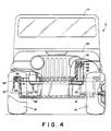
- the fourth and fifth transverse members 24 and 25 are generally U-shaped with L-shaped ends 26 as shown in Figs. 4 and 6. These L-shaped ends fit rather loosely in apertures in the intermediate portions 19 and 20 of the frame and are used to support the floor pan as described below.
- King pins 29 and 30 are also journalled on the frame 12 by passing through the first transverse frame member 21. These king pins 29 and 30 are unitary with spindles 31 and 32, respectively, on which the front wheels of the vehicle are journalled.
- a usual steering mechanism 33 is provided to turn the king pins 29 and 30 under guidance of a steering wheel 34.
- Four post bushings 35 are provided affixed to the frame 12 and these may be steel cups welded to the frame members. Two of these post bushings at the front of the vehicle surround the king pins 29 and 30 and the remaining two are at the rear on the second transverse frame member 22, and surround locator posts 37 and 38 affixed to the frame.
- the first body portion 13 includes generally the front of the vehicle and the second body portion 14 the rear of the vehicle. These two body portions 13 and 14 are better shown in Fig. 8, without all of the added parts which make the complete vehicle.
- the first body portion 13 is a unitary part and includes generally the front fenders 41, a battery box 42, the instrument panel 43 and first and second proximal sill portions 45 and 46, respectively. Each of these sill portions is generally an inverted U-shape, with the bight 47 of the U being atthetop and overlying the intermediate portions 19 and 20 of the longitudinal frame members. Alignment apertures 48 are provided in each of the sill portions 45 and 46, as shown in Figs. 7 and 8.
- the first body portion 13 also includes unitary posts 49 which are received in the front post bushings 35 on the frame 12.
- the second body portion 14 includes generally the rear quarter panels 51 with fender openings for the rear wheels, the seat base 52, a depressed floor pan 53, a hook 54 on the front or proximal end of the floor pan, and first and second sill portions 55 and 56 at the front or proximal end of this second body portion 14. All of the aforementioned parts are unitary and made in a single injection molded part.
- the first and second sill portions 55 and 56 are generally an inverted U-shape, as shown in Figs. 6, 7 and 8 and are complementary to the sill portions 45 and 46, respectively, on the first body 13.
- the inverted U-shape has a bight 57 of the U which is generally flat, horizontal and is complementary to and laps over the respective sill portions 45 and 46.
- Each sill portion 55 and 56 has a unitary post bushing 58, each of which contains an alignment aperture 59 into which a screw 60 with a washer 62 is installed.
- the post bushing 58 is received in the alignment aperture 48 of the first body portion 13, as shown in Fig. 7, and passes through apertures 61 in the intermediate portions 19 and 20 of the frame to locate the two body portions on the frame.
- the rear body portion 14 also includes unitary locator posts 63 which fit inside the post bushings 35, at the rear of the frame and unitary post bushings 64 secured nearthe rear of each frame by a sheet metal screw 65.
- the rear body portion floor pan 53 also includes two transverse grooves 66 and 67 to receive the U-shaped transverse frame members 24 and 25 respectively.
- the assembly of the vehicle 11 starts with the frame 12 being prepared as shown in Fig. 3.
- the frame will include the parts 17 through 33 and welded or secured as specified above.
- This frame will normally be disposed horizontally and the body portions 13 and 14 disposed above them. These body portions would be disposed as shown in Fig. 8 at a wide angled V with the proximal portions disposed adjacent each other.
- the battery box 42 may be rested on the top of the hook 54 and the forward end of the body portion 13 raised to the position shown in Fig. 8. This makes the sill portions 45 and 46 on the first body part straddling the floor pan 53 and below the sill portions 55 and 56 on the second body portion 14.
- the post bushings 58 on the sill portions 55 and 56 are one reason why this wide angle V is required and then the front end of the first body portion 13 may be lowered to pivot the sill portions 45 and 46 up into nested or overlapped position with the sill portions 55 and 56. This will make the two body portions in planar alignment and then the two body portions may be lowered onto the frame 12. In straightening the two body portions into alignment, the alignment apertures 48 in the sill portions 45 and 46 will be received on the post bushings, and the alignment apertures 48 may be slightly elongated to permit this. Then these post bushings 58 will be received in the apertures 61 in the intermediate portions of the longitudinal frame members 17 and 18.
- there are other locators for the body and frame Two of these locators are at the front of the vehicle where the unitary posts 49 are received in the post bushings 35 and the king pins 29 and 30 extend up through a flange 69.
- a friction cap 70 may be placed on the top of these king pins, and this retains the front of the body on the frame.
- Plastic engaging metal screws 60 may be driven from below up into the post bushings 58. At this time a seam edge 71 on the first body part 13 will be closely adjacent a seam edge 72 on the second' body portion 14. The dimensional tolerance between the king pin apertures and the alignment apertures 48 will determine the closeness of the seam edges 71 and 72.
- the post bushings 63 will be received in the post bushings 35 on the frame and pass over the locator posts 37 and 38. Friction caps 72 may be placed on these locator posts to secure the body portion 14 to the frame. Also, the post bushings 64 will rest on the rear end of the frame and may be secured thereto by the sheet metal screws 65 into preformed apertures in the frame again to secure the rear of the vehicle to the frame.
- the U-shaped transverse frame members 24 and 25 will be nested in the grooves 66 and 67, respectively, to provide reinforcement for the depressed floor pan, for example, when a child stands up in the vehicle.
- the front end of the second body portion 14 is narrowed, generally in accordance with the narrowing of the frame members 17 and 18, and the hook 54 at the front end of this body portion 14 is sufficiently narrow to be hooked over the relatively short third transverse frame 23.
- This provides support for the front end of the floor pan, and the battery box 42 comes down to within a small distance, for example 1/16th of an inch (1,6 mm), above the top of the hook 54. Since the battery box is a unitary part of the first body portion 13, the hook 54 cannot become disengaged from the transverse frame member 23.
- the vehicle 11 may be completed by adding the steering column and steering wheel 34, a windshield 77, seats 78, roll bar 79, hood 80, wheels 81 and a power train including an electric motor 82 as well as other finishing touches.
Landscapes
- Engineering & Computer Science (AREA)
- Mechanical Engineering (AREA)
- Architecture (AREA)
- Structural Engineering (AREA)
- Chemical & Material Sciences (AREA)
- Combustion & Propulsion (AREA)
- Transportation (AREA)
- Body Structure For Vehicles (AREA)
Claims (17)
die Befestigungselemente (60) die sich überlappenden Trittbereiche an dem Rahmen (12) halten, während die Falznahtkanten (71, 72) des ersten und des zweiten Karosserieteils (13, 14) nahe zusammenliegen.
Applications Claiming Priority (2)
| Application Number | Priority Date | Filing Date | Title |
|---|---|---|---|
| US910019 | 1986-09-22 | ||
| US06/910,019 US4709958A (en) | 1986-09-22 | 1986-09-22 | Ridable vehicle and assembly method |
Publications (3)
| Publication Number | Publication Date |
|---|---|
| EP0286667A1 EP0286667A1 (de) | 1988-10-19 |
| EP0286667A4 EP0286667A4 (de) | 1989-01-26 |
| EP0286667B1 true EP0286667B1 (de) | 1990-09-19 |
Family
ID=25428190
Family Applications (1)
| Application Number | Title | Priority Date | Filing Date |
|---|---|---|---|
| EP87906710A Expired EP0286667B1 (de) | 1986-09-22 | 1987-09-18 | Fahrbares fahrzeug und montageverfahren |
Country Status (5)
| Country | Link |
|---|---|
| US (1) | US4709958A (de) |
| EP (1) | EP0286667B1 (de) |
| JP (1) | JPH01501219A (de) |
| AU (1) | AU8077687A (de) |
| WO (1) | WO1988001960A1 (de) |
Families Citing this family (31)
| Publication number | Priority date | Publication date | Assignee | Title |
|---|---|---|---|---|
| AU584821B1 (en) * | 1987-11-02 | 1989-06-01 | Hong Rong Lian | A children's mini-car |
| US4988143A (en) * | 1990-02-08 | 1991-01-29 | Kransco | Dashboard assembly for children's ride-on-vehicle |
| US5106150A (en) * | 1990-02-09 | 1992-04-21 | Spang & Co. | Roof structure for toy vehicle |
| USD328317S (en) | 1990-10-12 | 1992-07-28 | Kransco | Ride-on toy vehicle |
| FR2671320B1 (fr) * | 1991-01-08 | 1995-07-28 | Renault | Structure avant pour vehicules automobiles. |
| SE9100108L (sv) * | 1991-01-14 | 1992-07-15 | Silent Power Sweden Ab | Ram-karosskombination foer ett 3-hjuligt, foeretraedesvis eldrivet laettviktsfordon |
| US5174627A (en) * | 1991-06-14 | 1992-12-29 | The Dow Chemical Company | Vehicle structure |
| US5294153A (en) * | 1993-01-27 | 1994-03-15 | Flexible Flyer Acquisition Corp. | Riding toy for children |
| NO301268B1 (no) * | 1993-05-07 | 1997-10-06 | Ringdal Patenter As | Forsterket frontdel for bruk ved fremstilling av kabiner/karosserier for kjöretöyer |
| USD362279S (en) | 1994-07-29 | 1995-09-12 | The Little Tikes Company | Toy vehicle |
| AU721166B2 (en) * | 1996-01-12 | 2000-06-22 | Mattel, Inc. | Adjustable axle mounting assembly for children's ride-on vehicles |
| US5718454A (en) * | 1996-01-12 | 1998-02-17 | Mattel, Inc. | Roll bar coupler for child's ride-on vehicle |
| ZA978309B (en) * | 1996-09-17 | 1998-09-03 | Raceco International Inc | Space frame for vehicle |
| USD397737S (en) | 1996-12-31 | 1998-09-01 | Mattel, Inc. | Children's ride-on toy vehicle |
| USD393888S (en) | 1997-02-10 | 1998-04-28 | Mattel, Inc. | Children's ride-on vehicle |
| DE29703663U1 (de) * | 1997-02-28 | 1998-08-20 | Sommer Ulrich | Personenkraftwagen mit einer tragenden Struktur, die mindestens zwei Längsträger aufweist |
| USD414140S (en) | 1997-10-10 | 1999-09-21 | Raceco International, Inc. | Vehicle |
| US5975625A (en) * | 1997-10-17 | 1999-11-02 | Ford Motor Company | Automotive vehicle body having a plastic outer body and an inner metal frame |
| USD422320S (en) * | 1998-01-28 | 2000-04-04 | Mattel, Inc. | Children's ride-on vehicle |
| US5931524A (en) * | 1998-01-28 | 1999-08-03 | Mattel, Inc. | Latch mechanism for a pivotal door on a child's ride-on vehicle |
| USD428076S (en) * | 1998-06-09 | 2000-07-11 | Rubbermaid Incorporated | Toy car |
| US6631925B1 (en) * | 2000-02-14 | 2003-10-14 | William M. Lawson, Jr. | Miniaturized motor vehicle |
| US6588189B2 (en) | 2001-01-09 | 2003-07-08 | Case Corporation | Compound bend chassis frame for a harvesting machine |
| US6918627B2 (en) * | 2001-10-11 | 2005-07-19 | The Best Automotive Toy Art Company (The B.A.T.A. Co.) | Toy vehicles having interchangeable body styles |
| US7568753B2 (en) | 2006-06-15 | 2009-08-04 | Mattel, Inc. | Children's ride-on vehicles with reconfigured bodies and methods for forming the same |
| US8038160B2 (en) * | 2008-01-25 | 2011-10-18 | Radio Flyer Inc. | Caster mounting arrangement for ride-on toy |
| USD601640S1 (en) | 2009-03-31 | 2009-10-06 | Mattel, Inc. | Partial chassis for a children's ride-on vehicle |
| US8382005B1 (en) * | 2011-04-26 | 2013-02-26 | Brandon A. Fletcher | Rideable toy |
| US9150102B1 (en) | 2014-05-01 | 2015-10-06 | Mattel, Inc. | Chassis assemblies with repositionable gearbox for children's ride-on vehicles, and assembly methods |
| CN105292360A (zh) * | 2015-10-29 | 2016-02-03 | 嘉兴哈雷童车有限公司 | 电动童车的前轮避震结构 |
| USD1072963S1 (en) * | 2024-03-13 | 2025-04-29 | Shanghai Longqian Toys Co., Ltd. | Toy sanitation vehicle |
Family Cites Families (3)
| Publication number | Priority date | Publication date | Assignee | Title |
|---|---|---|---|---|
| US2973220A (en) * | 1959-04-02 | 1961-02-28 | Alan M White | Plastic car body and method of manufacturing same |
| US4453763A (en) * | 1982-04-13 | 1984-06-12 | Trihawk, Inc. | Frame and body construction for automotive passenger vehicle |
| US4513981A (en) * | 1983-05-04 | 1985-04-30 | Degraaff Robert | Ride-on toy vehicle with front wheel drive and outboard front wheels |
-
1986
- 1986-09-22 US US06/910,019 patent/US4709958A/en not_active Ceased
-
1987
- 1987-09-18 AU AU80776/87A patent/AU8077687A/en not_active Withdrawn
- 1987-09-18 WO PCT/US1987/002415 patent/WO1988001960A1/en not_active Ceased
- 1987-09-18 JP JP62505363A patent/JPH01501219A/ja active Granted
- 1987-09-18 EP EP87906710A patent/EP0286667B1/de not_active Expired
Also Published As
| Publication number | Publication date |
|---|---|
| AU8077687A (en) | 1988-04-07 |
| US4709958A (en) | 1987-12-01 |
| JPH01501219A (ja) | 1989-04-27 |
| EP0286667A1 (de) | 1988-10-19 |
| JPH0476719B2 (de) | 1992-12-04 |
| EP0286667A4 (de) | 1989-01-26 |
| WO1988001960A1 (en) | 1988-03-24 |
Similar Documents
| Publication | Publication Date | Title |
|---|---|---|
| US4709958A (en) | Ridable vehicle and assembly method | |
| USRE33769E (en) | Ridable vehicle and assembly method | |
| JPH0569059A (ja) | 自動車用操舵軸の管体 | |
| EP0873249B1 (de) | Einstellbare abstützvorrichtung für ein kinderfahrzeug | |
| JPH0163563U (de) | ||
| JPS6239934Y2 (de) | ||
| JPS629192Y2 (de) | ||
| JPH0714048Y2 (ja) | 移動農機の燃料タンク取付構造 | |
| JPH0617664Y2 (ja) | 自動車のリヤピラー部構造 | |
| JPS63111365U (de) | ||
| JPH0418939Y2 (de) | ||
| JPS6144923Y2 (de) | ||
| JPH07304468A (ja) | トラクタのロプス装置 | |
| JPS61132166U (de) | ||
| JPS63108870U (de) | ||
| JPH0370557U (de) | ||
| JPH039932U (de) | ||
| JPH061112U (ja) | 自動車のステアリングコラム支持装置 | |
| JPH04123774U (ja) | 自動車のステアリングコラム支持構造 | |
| JPH0218777U (de) | ||
| JPS61148768U (de) | ||
| JPS6452847U (de) | ||
| JPS639082U (de) | ||
| JPH043873U (de) | ||
| JPH02117273U (de) |
Legal Events
| Date | Code | Title | Description |
|---|---|---|---|
| PUAI | Public reference made under article 153(3) epc to a published international application that has entered the european phase |
Free format text: ORIGINAL CODE: 0009012 |
|
| AK | Designated contracting states |
Kind code of ref document: A1 Designated state(s): DE FR GB IT |
|
| 17P | Request for examination filed |
Effective date: 19880913 |
|
| A4 | Supplementary search report drawn up and despatched |
Effective date: 19890126 |
|
| 17Q | First examination report despatched |
Effective date: 19891103 |
|
| GRAA | (expected) grant |
Free format text: ORIGINAL CODE: 0009210 |
|
| AK | Designated contracting states |
Kind code of ref document: B1 Designated state(s): DE FR GB IT |
|
| ITF | It: translation for a ep patent filed | ||
| ET | Fr: translation filed | ||
| REF | Corresponds to: |
Ref document number: 3765115 Country of ref document: DE Date of ref document: 19901025 |
|
| PLBE | No opposition filed within time limit |
Free format text: ORIGINAL CODE: 0009261 |
|
| STAA | Information on the status of an ep patent application or granted ep patent |
Free format text: STATUS: NO OPPOSITION FILED WITHIN TIME LIMIT |
|
| 26N | No opposition filed | ||
| REG | Reference to a national code |
Ref country code: GB Ref legal event code: IF02 |
|
| PGFP | Annual fee paid to national office [announced via postgrant information from national office to epo] |
Ref country code: FR Payment date: 20060918 Year of fee payment: 20 |
|
| PGFP | Annual fee paid to national office [announced via postgrant information from national office to epo] |
Ref country code: GB Payment date: 20060925 Year of fee payment: 20 |
|
| PGFP | Annual fee paid to national office [announced via postgrant information from national office to epo] |
Ref country code: IT Payment date: 20060930 Year of fee payment: 20 |
|
| PGFP | Annual fee paid to national office [announced via postgrant information from national office to epo] |
Ref country code: DE Payment date: 20061031 Year of fee payment: 20 |
|
| REG | Reference to a national code |
Ref country code: GB Ref legal event code: PE20 |
|
| PG25 | Lapsed in a contracting state [announced via postgrant information from national office to epo] |
Ref country code: GB Free format text: LAPSE BECAUSE OF EXPIRATION OF PROTECTION Effective date: 20070917 |