EP0873741A2 - Déambulateur - Google Patents
Déambulateur Download PDFInfo
- Publication number
- EP0873741A2 EP0873741A2 EP97110411A EP97110411A EP0873741A2 EP 0873741 A2 EP0873741 A2 EP 0873741A2 EP 97110411 A EP97110411 A EP 97110411A EP 97110411 A EP97110411 A EP 97110411A EP 0873741 A2 EP0873741 A2 EP 0873741A2
- Authority
- EP
- European Patent Office
- Prior art keywords
- walker
- leg members
- support member
- armrests
- pair
- Prior art date
- Legal status (The legal status is an assumption and is not a legal conclusion. Google has not performed a legal analysis and makes no representation as to the accuracy of the status listed.)
- Withdrawn
Links
Images


Classifications
-
- A—HUMAN NECESSITIES
- A61—MEDICAL OR VETERINARY SCIENCE; HYGIENE
- A61H—PHYSICAL THERAPY APPARATUS, e.g. DEVICES FOR LOCATING OR STIMULATING REFLEX POINTS IN THE BODY; ARTIFICIAL RESPIRATION; MASSAGE; BATHING DEVICES FOR SPECIAL THERAPEUTIC OR HYGIENIC PURPOSES OR SPECIFIC PARTS OF THE BODY
- A61H3/00—Appliances for aiding patients or disabled persons to walk about
- A61H3/04—Wheeled walking aids for patients or disabled persons
- A61H2003/046—Wheeled walking aids for patients or disabled persons with braking means
Definitions
- This invention relates to a walker used to help a handicapped person having difficulty in walking while supporting his or her body.
- Fig. 14 shows a conventional walker, which comprises a frame 50 carrying at its bottom a pair of front wheels 51 and a pair of rear wheels 52. Each front wheel 51 is pivotable about a vertical shaft 53. A horseshoe-shaped armrest 54 is mounted on top of the frame 50 with its opening facing rearward.
- a person with a walking problem can walk with this walker in any desired direction while supporting his or her arms on the armrest 54.
- This walker having an armrest that is closed at front and open at the rear, can stably support the body of a person with a rather serious walking problem at the front closed end of the armrest, because the upper torso of such a person is typically hunched forward. But this walker will be inconvenient for a person who has less difficulty in walking, because such a person can walk substantially in erect position and thus needs to be supported on his or her back. But the armrest of this walker cannot support the back of a user because its rear is open.
- Another problem of this walker is that it is impossible to change the height or width of the armrest.
- a user usually moves in a desired direction by leaning his or her body on the armrest. In order to stop, he or she has to stand rather firmly on his or her own foot or feet. For a person who cannot do this, it is a major problem to stop at a desired point.
- An object of this invention is to provide a walker which is adapted for every one of those who have widely different degrees of difficulty in walking.
- a walker comprising a pair of leg members each having a front wheel pivotable about a vertical shaft, a rear wheel and a pair of legs, and a support member detachably mounted on the leg members and having a pair of armrests and a support rod provided at one end thereof and extending in a width direction, wherein the support member can be raised and lowered relative to the leg members and can be turned 180 ° so that its front and back are reversed relative to the leg members and the distance between the armrests is adjustable.
- the support member on the leg members with its support rod located either at front or back of the walker, i.e. in front or back of the user, and to adjust the height of the armrests by raising and lowering the support member relative to the leg members, as well as the distance between the armrests.
- each rear wheel By providing each rear wheel with the rotation resistance generator, it is possible to adjust the braking force applied to the rear wheel. For example, it is possible to increase the braking force when the walker is used by a person with a serious walking problem so that the walker will not move even if the user lean on the walker.
- each rear wheel By providing each rear wheel with the reverse rotation preventive means, it is possible to prevent the walker from moving backward. Thus, the user can safely lean his or her back on the walker.
- each front wheel By providing each front wheel with the stopper, it is possible to keep the moving direction of the walker constant.
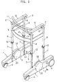
- the walker of this embodiment comprises a pair of right and left leg members 1, and a support member 2 mounted on top of the leg members 1.
- Each leg member 1 comprises a wheel carriage 3 carrying a front wheel 4 pivotable about a vertical shaft 6, and a rear wheel 5, and two legs 7 vertically extending from the inner side of the wheel carriage 3.
- the support member 2 comprises a pair of right and left armrests 10, and four vertical shafts 8 connected to the front and rear ends of the armrests 10 by mounting rods 9 and coupled to the respective legs 7, and plate members provided between the shafts 8 at one end of the support member 2 and between the two shafts 8 on either side of the support member.
- a support rod 11 extends widthwise over the armrests 10 at said one end of the support member 2.
- the shafts 8 are tubular members having bottom openings into which are slidably inserted the respective legs 7.
- the legs 7 and shafts 8 are fixed together by clamps 12. By loosening the clamps 12, the support member 2 can be raised or lowered relative to the leg members 1 or pulled upwardly out of the leg members 1.
- the armrests 10 are slidable relative to the mounting rods 9 and can be fixed to the mounting rods 9 by clamps 13. By loosening the clamps 13, the armrests 10 can be moved in the width direction of the support member 2.
- the support member 2 is mounted so that the support rod 11 is at the front end of the walker.
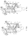
- this person can walk while gripping the support rod 11 with his or her forearms resting on the armrests with the arms folded, as shown in Fig. 3.
- the walker is to be used by a person with a medium degree of walking problem, who can walk with his upper torso more or less erect and with his or her arms straightened and put on the armrests 10 as shown in Fig. 4, he or she can always support his or her body on the support rod 11. This can give the user a sense of security.
- this walker is to be used by a person with a lighter degree of walking problem, who can walk substantially in an erect posture, the support member 2 is pulled up out of the leg members 1, turned 180° horizontally, and coupled to the leg members 1 again so that the support rod 11 is positioned at the back of the walker. In this arrangement, the support rod 11 is used to support the back of the user.
- the height of the armrests 10 by raising and lowering the support member 2 relative to the leg members 1 and the distance between the armrests 10 by moving them in the width direction of the support member 2.
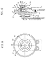
- a rotation resistance generator 20 is provided in the center of each wheel carriage 3. To each rotation resistance generator 20, the rotation of the rear wheel 5 is transmitted through endless belts 21, 22.
- the belt 21 extends around pulleys 23 and 24, while the belt 22 extends around pulleys 25 and 26. Fixed to a rotary shaft of the rear wheel 5, the pulley 23 rotates with the rear wheel 5.
- the pulley 26 is mounted in the rotation resistance generator 20.
- the pulleys 23 to 26 and the belts 21, 22 are all toothed and in mesh with each other.
- each rotation resistance generator 20 has magnets 29, 30 provided in a case 28 opposite to each other, and a metallic rotary plate 31 provided between the magnets 29, 30 and adapted to rotate together with the pulley 26. As the rotary plate 31 rotates, rotation resistance resulting from eddy current produced on its surface is applied to the pulley 26, thus braking the rear wheel 5.
- the magnet 29 is fixed to the case 28, while the other magnet 30 is mounted on a support plate 32a which can be rotated relative to the case 28, coupled with a lever 32.
- a lever 32 By operating the lever 32, the relative position between the magnets 29 and 30 and the rotation resistance applied to the pulley 26 change, so that it is possible to adjust the braking force applied to the rear wheel 5.
- a brake 33 is mounted in the case 28. By operating the lever 32, it is possible to move the brake 33 into mesh with the pulley 26, thereby completely stopping the rotation of the pulley 26 and locking the rear wheel 5.
- the pulley 24 of the clutch 27 has a boss 34 slidably fitted in the pulley 25.
- the boss 34 carries on its end face a knob 35 that is rotatable by a predetermined angle, and a knob core 37 biasing the knob 35 against the pulley 25 through a disc spring 36.
- the knob 35 rotates, the head of a mounting screw 38 of the knob core 37 engages and disengages from a recess 39 formed in the back of the knob 35.
- the knob 35 and the pulley 25 are moved in the axial direction of the boss 34, so that the pulleys 24 and 25 can be connected and disconnected.
- the levers 32 are moved to a position where a large braking force is applied to the rear wheels 5 so that the walker would not move simply by leaning the user's body against the walker.
- Each rear wheel 5 has, as seen in Fig. 6, a reverse rotation preventive mechanism 40.
- This reverse rotation preventive mechanism 40 comprises a ratchet wheel 41 nonrotatably mounted on the rear wheel 5, and a claw 42 urged toward the outer periphery of the ratchet wheel 41. This mechanism can be disengaged by moving the claw 42 away from the ratchet wheel 41 by turning a knob 43.
- each front wheel 4 has a stopper 44 which includes a pin 48 which is moved into and out of a hole 46 formed in a front wheel cover 45 by operating a lever 47.
- the pin 48 When the pin 48 is inserted in the hole 46, the front wheel 4 cannot rotate.
- the lever 47 pivots about the pin 48.
- the pin 48 When the lever 47 is in its horizontal position, the pin 48 can move into and out of the hole 46.
- the lever When the lever is turned down, the pin cannot move.
Landscapes
- Health & Medical Sciences (AREA)
- Epidemiology (AREA)
- Pain & Pain Management (AREA)
- Physical Education & Sports Medicine (AREA)
- Rehabilitation Therapy (AREA)
- Life Sciences & Earth Sciences (AREA)
- Animal Behavior & Ethology (AREA)
- General Health & Medical Sciences (AREA)
- Public Health (AREA)
- Veterinary Medicine (AREA)
- Rehabilitation Tools (AREA)
Applications Claiming Priority (3)
| Application Number | Priority Date | Filing Date | Title |
|---|---|---|---|
| JP104646/97 | 1997-04-22 | ||
| JP9104646A JPH10295749A (ja) | 1997-04-22 | 1997-04-22 | 歩行補助器 |
| JP10464697 | 1997-04-22 |
Publications (2)
| Publication Number | Publication Date |
|---|---|
| EP0873741A2 true EP0873741A2 (fr) | 1998-10-28 |
| EP0873741A3 EP0873741A3 (fr) | 1999-06-23 |
Family
ID=14386235
Family Applications (1)
| Application Number | Title | Priority Date | Filing Date |
|---|---|---|---|
| EP97110411A Withdrawn EP0873741A3 (fr) | 1997-04-22 | 1997-06-25 | Déambulateur |
Country Status (3)
| Country | Link |
|---|---|
| EP (1) | EP0873741A3 (fr) |
| JP (1) | JPH10295749A (fr) |
| CA (1) | CA2208656A1 (fr) |
Cited By (7)
| Publication number | Priority date | Publication date | Assignee | Title |
|---|---|---|---|---|
| WO2001024759A1 (fr) * | 1999-10-06 | 2001-04-12 | Nicolaisen Kurt A | Ambulateur a largeur reglable |
| WO2002062285A1 (fr) * | 2001-02-07 | 2002-08-15 | Soerensen Ralf Henry Harbo | Dispositif a monter sur un cadre de marche du type rollator et cadre de marche du type rollateur dote dudit dispositif |
| FR2826567A1 (fr) * | 2001-06-29 | 2003-01-03 | Chevalier Michele Langlet | Dispositif de deambulation pour personnes a mobilite reduite |
| WO2008034141A1 (fr) * | 2006-09-15 | 2008-03-20 | The Dashaway Company | Appareil de mobilisation utilisé à des fins d'exercice, de rééducation et de bien-être |
| CN103989569A (zh) * | 2014-04-21 | 2014-08-20 | 成都科创佳思科技有限公司 | 下肢康复装置 |
| CN104758145A (zh) * | 2014-01-06 | 2015-07-08 | 上海理工大学 | 用于双气囊减重训练装置的上部气囊支架 |
| CN108524206A (zh) * | 2018-05-09 | 2018-09-14 | 焦若涵 | 助行器 |
Families Citing this family (4)
| Publication number | Priority date | Publication date | Assignee | Title |
|---|---|---|---|---|
| DE4137606C1 (fr) * | 1991-11-15 | 1992-07-30 | Schott Glaswerke, 6500 Mainz, De | |
| JP5672616B2 (ja) * | 2012-01-24 | 2015-02-18 | 松宝産業株式会社 | 身体起立支援支持具付き歩行器 |
| JP2018007784A (ja) * | 2016-07-12 | 2018-01-18 | 東億 林 | 車輪付き歩行器の抵抗力制御構造 |
| CN113208880B (zh) * | 2021-04-22 | 2023-08-22 | 昆明市中医医院 | 一种骨科护理助行装置及使用方法 |
Family Cites Families (3)
| Publication number | Priority date | Publication date | Assignee | Title |
|---|---|---|---|---|
| US4094330A (en) * | 1977-01-14 | 1978-06-13 | Jong Slosson B | Walker |
| US4748994A (en) * | 1986-01-17 | 1988-06-07 | Guardian Products, Inc. | Reversible walker device |
| CA2022180C (fr) * | 1990-07-27 | 1995-06-06 | Amy E. Lowen | Aide a la marche |
-
1997
- 1997-04-22 JP JP9104646A patent/JPH10295749A/ja active Pending
- 1997-06-24 CA CA 2208656 patent/CA2208656A1/fr not_active Abandoned
- 1997-06-25 EP EP97110411A patent/EP0873741A3/fr not_active Withdrawn
Cited By (9)
| Publication number | Priority date | Publication date | Assignee | Title |
|---|---|---|---|---|
| WO2001024759A1 (fr) * | 1999-10-06 | 2001-04-12 | Nicolaisen Kurt A | Ambulateur a largeur reglable |
| WO2002062285A1 (fr) * | 2001-02-07 | 2002-08-15 | Soerensen Ralf Henry Harbo | Dispositif a monter sur un cadre de marche du type rollator et cadre de marche du type rollateur dote dudit dispositif |
| FR2826567A1 (fr) * | 2001-06-29 | 2003-01-03 | Chevalier Michele Langlet | Dispositif de deambulation pour personnes a mobilite reduite |
| WO2008034141A1 (fr) * | 2006-09-15 | 2008-03-20 | The Dashaway Company | Appareil de mobilisation utilisé à des fins d'exercice, de rééducation et de bien-être |
| US8215652B2 (en) | 2006-09-15 | 2012-07-10 | Dashaway Company | Mobilizer for exercise, rehabilitation and wellness |
| US8596658B1 (en) | 2006-09-15 | 2013-12-03 | Dashaway Company | Mobilizer for exercise, rehabilitation and wellness |
| CN104758145A (zh) * | 2014-01-06 | 2015-07-08 | 上海理工大学 | 用于双气囊减重训练装置的上部气囊支架 |
| CN103989569A (zh) * | 2014-04-21 | 2014-08-20 | 成都科创佳思科技有限公司 | 下肢康复装置 |
| CN108524206A (zh) * | 2018-05-09 | 2018-09-14 | 焦若涵 | 助行器 |
Also Published As
| Publication number | Publication date |
|---|---|
| JPH10295749A (ja) | 1998-11-10 |
| CA2208656A1 (fr) | 1998-10-22 |
| EP0873741A3 (fr) | 1999-06-23 |
Similar Documents
| Publication | Publication Date | Title |
|---|---|---|
| US5803103A (en) | Walker | |
| US6220995B1 (en) | Exerciser | |
| US6976698B2 (en) | Manually operable standing wheelchair | |
| KR101245543B1 (ko) | 조정 가능한 활강 트랙 저항 및 제동 장치를 구비한 계단식의자 | |
| US9004598B2 (en) | Seating system for a recumbent stepper | |
| CA2648059C (fr) | Dispositif repliable servant a soulever un patient | |
| JPH04507212A (ja) | スライド移動装置 | |
| EP0873741A2 (fr) | Déambulateur | |
| EP0618103A1 (fr) | Siège de véhicule | |
| EP0456718A1 (fr) | Appareil de marche combine a un fauteuil roulant | |
| EP0278974A1 (fr) | Chaise roulante et dispositif d'aide a la marche combines | |
| US4927167A (en) | Ambulatory wheelstand | |
| RU2006103071A (ru) | Устройство для регулирования высоты детского сиденья и раздвижная регулируемая подножка | |
| JP2001178788A (ja) | 歩行補助車 | |
| US6224077B1 (en) | Link lifting gear for a baby-walker | |
| US4995628A (en) | Standing frame assembly for use with wheelchair | |
| KR101310841B1 (ko) | 전동휠체어용 암레스트 | |
| US6286904B1 (en) | Pivotable abduction abutment support for wheelchair or the like | |
| JP3716013B2 (ja) | 学習机用の椅子 | |
| NO863921L (no) | Stoetteanordning for gaaende. | |
| CA2093072C (fr) | Siege pour vehicules | |
| JP2005177333A (ja) | 起立補助機能付き椅子 | |
| JP3369759B2 (ja) | 椅 子 | |
| JP2521300Y2 (ja) | 座位保持用車椅子 | |
| CN220423525U (zh) | 一种座板角度可调的座椅 |
Legal Events
| Date | Code | Title | Description |
|---|---|---|---|
| PUAI | Public reference made under article 153(3) epc to a published international application that has entered the european phase |
Free format text: ORIGINAL CODE: 0009012 |
|
| AK | Designated contracting states |
Kind code of ref document: A2 Designated state(s): DE DK FR GB IT SE |
|
| PUAL | Search report despatched |
Free format text: ORIGINAL CODE: 0009013 |
|
| AK | Designated contracting states |
Kind code of ref document: A3 Designated state(s): AT BE CH DE DK ES FI FR GB GR IE IT LI LU MC NL PT SE |
|
| 17P | Request for examination filed |
Effective date: 19991117 |
|
| AKX | Designation fees paid |
Free format text: DE DK FR GB IT SE |
|
| STAA | Information on the status of an ep patent application or granted ep patent |
Free format text: STATUS: THE APPLICATION HAS BEEN WITHDRAWN |
|
| 18W | Application withdrawn |
Withdrawal date: 20000630 |