EP0873798B1 - Fertigwalzwerk mit mehreren Ausläufen - Google Patents
Fertigwalzwerk mit mehreren Ausläufen Download PDFInfo
- Publication number
- EP0873798B1 EP0873798B1 EP98302451A EP98302451A EP0873798B1 EP 0873798 B1 EP0873798 B1 EP 0873798B1 EP 98302451 A EP98302451 A EP 98302451A EP 98302451 A EP98302451 A EP 98302451A EP 0873798 B1 EP0873798 B1 EP 0873798B1
- Authority
- EP
- European Patent Office
- Prior art keywords
- pass line
- rolling
- cooling bed
- finishing
- process section
- Prior art date
- Legal status (The legal status is an assumption and is not a legal conclusion. Google has not performed a legal analysis and makes no representation as to the accuracy of the status listed.)
- Expired - Lifetime
Links
- 238000005096 rolling process Methods 0.000 claims abstract description 30
- 238000000034 method Methods 0.000 claims abstract description 24
- 230000008569 process Effects 0.000 claims abstract description 23
- 238000001816 cooling Methods 0.000 claims abstract description 15
- 238000004513 sizing Methods 0.000 description 3
- 230000015572 biosynthetic process Effects 0.000 description 2
- 230000007246 mechanism Effects 0.000 description 2
- 230000003014 reinforcing effect Effects 0.000 description 2
- 238000010276 construction Methods 0.000 description 1
- 230000008878 coupling Effects 0.000 description 1
- 238000010168 coupling process Methods 0.000 description 1
- 238000005859 coupling reaction Methods 0.000 description 1
- 230000006872 improvement Effects 0.000 description 1
- 238000004519 manufacturing process Methods 0.000 description 1
- 230000008707 rearrangement Effects 0.000 description 1
- 230000009467 reduction Effects 0.000 description 1
- XLYOFNOQVPJJNP-UHFFFAOYSA-N water Substances O XLYOFNOQVPJJNP-UHFFFAOYSA-N 0.000 description 1
Images




Classifications
-
- B—PERFORMING OPERATIONS; TRANSPORTING
- B21—MECHANICAL METAL-WORKING WITHOUT ESSENTIALLY REMOVING MATERIAL; PUNCHING METAL
- B21B—ROLLING OF METAL
- B21B1/00—Metal-rolling methods or mills for making semi-finished products of solid or profiled cross-section; Sequence of operations in milling trains; Layout of rolling-mill plant, e.g. grouping of stands; Succession of passes or of sectional pass alternations
- B21B1/16—Metal-rolling methods or mills for making semi-finished products of solid or profiled cross-section; Sequence of operations in milling trains; Layout of rolling-mill plant, e.g. grouping of stands; Succession of passes or of sectional pass alternations for rolling wire rods, bars, merchant bars, rounds wire or material of like small cross-section
- B21B1/18—Metal-rolling methods or mills for making semi-finished products of solid or profiled cross-section; Sequence of operations in milling trains; Layout of rolling-mill plant, e.g. grouping of stands; Succession of passes or of sectional pass alternations for rolling wire rods, bars, merchant bars, rounds wire or material of like small cross-section in a continuous process
-
- B—PERFORMING OPERATIONS; TRANSPORTING
- B21—MECHANICAL METAL-WORKING WITHOUT ESSENTIALLY REMOVING MATERIAL; PUNCHING METAL
- B21B—ROLLING OF METAL
- B21B39/00—Arrangements for moving, supporting, or positioning work, or controlling its movement, combined with or arranged in, or specially adapted for use in connection with, metal-rolling mills
- B21B39/14—Guiding, positioning or aligning work
-
- B—PERFORMING OPERATIONS; TRANSPORTING
- B21—MECHANICAL METAL-WORKING WITHOUT ESSENTIALLY REMOVING MATERIAL; PUNCHING METAL
- B21B—ROLLING OF METAL
- B21B39/00—Arrangements for moving, supporting, or positioning work, or controlling its movement, combined with or arranged in, or specially adapted for use in connection with, metal-rolling mills
-
- B—PERFORMING OPERATIONS; TRANSPORTING
- B21—MECHANICAL METAL-WORKING WITHOUT ESSENTIALLY REMOVING MATERIAL; PUNCHING METAL
- B21B—ROLLING OF METAL
- B21B39/00—Arrangements for moving, supporting, or positioning work, or controlling its movement, combined with or arranged in, or specially adapted for use in connection with, metal-rolling mills
- B21B39/14—Guiding, positioning or aligning work
- B21B39/18—Switches for directing work in metal-rolling mills or trains
-
- B—PERFORMING OPERATIONS; TRANSPORTING
- B21—MECHANICAL METAL-WORKING WITHOUT ESSENTIALLY REMOVING MATERIAL; PUNCHING METAL
- B21B—ROLLING OF METAL
- B21B1/00—Metal-rolling methods or mills for making semi-finished products of solid or profiled cross-section; Sequence of operations in milling trains; Layout of rolling-mill plant, e.g. grouping of stands; Succession of passes or of sectional pass alternations
- B21B1/08—Metal-rolling methods or mills for making semi-finished products of solid or profiled cross-section; Sequence of operations in milling trains; Layout of rolling-mill plant, e.g. grouping of stands; Succession of passes or of sectional pass alternations for rolling structural sections, i.e. work of special cross-section, e.g. angle steel
- B21B1/0815—Metal-rolling methods or mills for making semi-finished products of solid or profiled cross-section; Sequence of operations in milling trains; Layout of rolling-mill plant, e.g. grouping of stands; Succession of passes or of sectional pass alternations for rolling structural sections, i.e. work of special cross-section, e.g. angle steel from flat-rolled products, e.g. by longitudinal shearing
-
- B—PERFORMING OPERATIONS; TRANSPORTING
- B21—MECHANICAL METAL-WORKING WITHOUT ESSENTIALLY REMOVING MATERIAL; PUNCHING METAL
- B21B—ROLLING OF METAL
- B21B13/00—Metal-rolling stands, i.e. an assembly composed of a stand frame, rolls, and accessories
- B21B2013/003—Inactive rolling stands
-
- B—PERFORMING OPERATIONS; TRANSPORTING
- B21—MECHANICAL METAL-WORKING WITHOUT ESSENTIALLY REMOVING MATERIAL; PUNCHING METAL
- B21B—ROLLING OF METAL
- B21B31/00—Rolling stand structures; Mounting, adjusting, or interchanging rolls, roll mountings, or stand frames
- B21B31/02—Rolling stand frames or housings; Roll mountings ; Roll chocks
- B21B2031/026—Transverse shifting the stand
-
- B—PERFORMING OPERATIONS; TRANSPORTING
- B21—MECHANICAL METAL-WORKING WITHOUT ESSENTIALLY REMOVING MATERIAL; PUNCHING METAL
- B21B—ROLLING OF METAL
- B21B35/00—Drives for metal-rolling mills, e.g. hydraulic drives
- B21B35/14—Couplings, driving spindles, or spindle carriers specially adapted for, or specially arranged in, metal-rolling mills
Definitions
- This invention relates generally to rolling mills, and is concerned in particular with an improvement to the finishing section of a single strand bar mill.
- the roll stands of conventional bar mills are usually aligned along a single pass line. Where slitting is being practised, the roll stands of the roughing and intermediate mill sections are again aligned along a common pass line, with two sets of roll stands in the finishing section being aligned along parallel pass lines arranged to receive the slit sections. In both cases, the arrangement of the roll stands in the finishing section imposes severe limitations on the range of products the mill is able to produce.
- the present invention is directed to a novel rearrangement of the roll stands of the finishing section to thereby broaden the range of products capable of being produced by the mill.
- the finishing section is provided with two laterally shiftable four stand finishing blocks.
- the blocks are positioned on parallel pass lines arranged to roll slit strands into relatively low quality bar products, e.g. reinforcing bars.
- the slitter is bypassed and one or the other of the finishing blocks is shifted onto the main pass line to roll high quality bar products from a single strand received directly from the intermediate mill section.
- the product exiting from one or the other finishing blocks is directed to an additional downstream block where it is rolled into rod.
- each of the laterally shiftable blocks is further subdivided into two laterally shiftable two stand blocks, and in a third embodiment two stationary two stand blocks and a rod finishing block are arranged in a staggered relationship on three parallel pass lines.
- a single strand bar mill in accordance with the present invention comprising roughing, intermediate and finishing sections.
- the roughing section includes roll stands 1H, 2V, 3H, 4V, 5H and 6V aligned along the main mill pass line P 1 .
- the intermediate mill section likewise includes roll stands 7H, 8V, 9H, 1OV, 11H, 12V, 13H and 14V aligned along the same pass line.
- Other components typically associated with the roughing and intermediate sections of the mill include water boxes 10 and shears 12. Billets enter roll stand 1H and proceed through the roughing and intermediate sections of the mill from left to right as viewed in Figure 1A.
- the resulting single strand process section Upon exiting from the intermediate section of the mill, the resulting single strand process section immediately enters the finishing section of the mill.
- This section includes a slitter 16 and a switch 18.
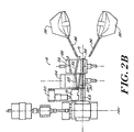
- the switch 18 includes two laterally traversable beds 24, 26.
- Bed 24 carries two angularly disposed guide troughs 28 and another guide trough 30 parallel to the main pass line P 1 .
- Bed 26 carries further angular guide extensions 32 and an additional straight guide trough 34.
- the slitter 16, guide troughs 28 and their extensions 32 are positioned on the main pass line P 1 .
- the first process section received from vertical stand 14V will be subdivided into second and third process sections by the slitter 16, and each of these subdivided process sections will be directed by guide troughs 28 and their extensions 32 to angularly disposed guide pipes 36 leading to side loopers 38.
- Side loopers are well known devices designed to accommodate the formation of horizontal loops in the product, which serve to relieve tension in the product as it passes from one roll pass to the next.
- a drive motor 44 has an output shaft 46 with an externally splined end 48 received in an internally splined tube 50 rotatably supported by bearings 52 carried in a housing 54.
- a shaft 56 has an externally splined end received in the internally splined tube 50 and its opposite end connected by a coupling 58 to one or the other of the finishing blocks 42 a , 42 b .
- a piston-cylinder unit 60 serves as the mechanism for laterally shifting the associated finishing block between the main mill pass line P 1 and the respective auxiliary pass line P 2 , P 3 .
- finishing blocks 42 a , 42 b are positioned as shown in Figure 1B, products exiting therefrom are redirected by appropriate guides 62 back towards the main mill pass line P 1 where they continue along parallel paths to the cooling bed 40.
- one of the finishing blocks 42 a , 42 b can feed a switch mechanism 64 which can be adjusted to divert the exiting product to a third path P 4 leading to a rod rolling block 66.
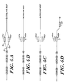
- Figure 4A is a diagrammatic representation of the rolling of slit products into lower quality smaller diameter bars, such products being typically used as reinforcing bars in the construction industry.
- Figure 4B illustrates the use of one of the finishing blocks 42 b to roll higher precision bars being received directly from the intermediate section of the mill.
- Figure 4C illustrates another operational mode where both finishing blocks 42 a , 42 b are bypassed and larger diameter bar products are directed from the intermediate section of the mill to the cooling bed.
- Figure 4D illustrates still another operational mode where one of the finishing blocks 42 b is employed to roll product received directly from the intermediate section of the mill, and the product exiting from that finishing block is in turn diverted to the rod rolling block 66 for the production of high quality rods.
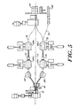
- the parallel pass lines P 2 ,P 3 are occupied respectively by pairs of two stand blocks 68a, 68b, and 68c, 68d with uploopers 70 between each pair of blocks.
- the slitter 16 is operated to divide the product received from vertical stand 14V, the slit strands are again diverted by the switch 18 via side loopers 38 to the rolling lines P 2 ,P 3 where they are rolled through the respective pairs of blocks before being redirected centrally to the cooling bed 40.
- the product emerging from block 68d can be switched to path P 4 for continued rolling in the rod rolling block 66.
- uplooper refers to a conventional apparatus designed to accommodate the controlled formation of a vertical loop in the product to thereby relieve tension which might otherwise develop in the product as it passes from one rolling block to the next.
- sizing mill' refers to a block of stands in which successive roll passes take relatively light reductions, usually in a round-round sequence, as disclosed for example in U.S. Patent No. 4,907,438.
- the slitter 16 is inoperative, and the switch 18 is set to direct product along pass line P 1 .
- One of the blocks 68b has been shifted onto pass line P 1 to finish roll the product prior to its being sized in mill 74.
- the product exiting from block 68b (or any of the other blocks 68a, 68c or 68d shifted onto pass line P1) can be directed along path P 4 to the rod rolling block 66 or along path P 1 to bar sizing mill.
- the present invention makes it possible to produce a wide range of products with a relatively modest outlay for capital equipment in the finishing section of the mill. This is due in large part to the use of laterally shiftable finishing blocks which can either be bypassed when rolling larger low quality bar, or used in tandem when rolling slit products, or employed alternatively when shifted onto the main rolling line to finish roll higher quality bars.
Landscapes
- Engineering & Computer Science (AREA)
- Mechanical Engineering (AREA)
- Metal Rolling (AREA)
- Disintegrating Or Milling (AREA)
- Electrophonic Musical Instruments (AREA)
- Finish Polishing, Edge Sharpening, And Grinding By Specific Grinding Devices (AREA)
Claims (6)
- Walzwerk, welches eine größere Anzahl von Walzgerüsten, die längs einer ersten Walzbahn (P') für die Walzung von langem Walzgut in ein erstes Bearbeitungsprofil aufeinanderfolgend angeordnet sind, und ein Kühlbett (40) zur Aufnahme des gewalzten Walzguts und Transportmittel (60) zum Verfahren eines Walzgerüsts von einer Walzbahn zu einer parallelen Walzbahn aufweist, dadurch gekennzeichnet, dass erste Führungsmittel (22, 30, 34) dafür vorgesehen sind, das besagte erste Bearbeitungsprofil längs der besagten ersten Walzbahn für das Auslaufen in das besagte Kühlbett zu leiten, wobei Fertigblöcke (42a, 42b) auf einer zweiten und einer dritten Walzbahn (P2, P3) parallel zur besagten ersten Walzbahn angeordnet sind, Mittel zum Längsschneiden (16) für das Teilen des besagten ersten Bearbeitungsprofils in ein zweites und drittes Bearbeitungsprofil vorhanden sind und zweite Hilfsmittel (28) vorgesehen sind, um das zweite bzw, dritte Bearbeitungsprofil zu der besagten zweiten und dritten Walzbahn zur fortgesetzten Walzung in den besagten Fertigblöcken zu leiten, bevor sie in das besagte Kühlbett ausgetragen werden, und wobei die besagten Transportmittel so angeordnet sind, dass sie wenigstens einen der Fertigblöcke auf die besagte erste Walzbahn für die zusätzliche Walzung des besagten ersten Bearbeitungsprofils vor dem Auslaufen zum besagten Kühlbett verfahren.
- Walzwerk nach Anspruch 1, bei dem die besagten Mittel zum Längsschneiden (16) und die besagten zweiten Führungsmittel (28) zwischen einer nichtoperativen Position seitlich der besagten ersten Walzbahn und einer operativen Position auf der besagten ersten Walzbahn verfahrbar sind.
- Walzwerk nach Anspruch 2, bei dem die besagten ersten Führungsmittel (22, 30, 34) zwischen einer nichtoperativen Position seitlich der besagten ersten Walzbahn und einer operativen Position verfahrbar sind, wenn die besagten Mittel zum Längsschneiden und die besagten zweiten Führungsmittel in ihre jeweilige nichtoperative Position verfahren werden.
- Walzwerk nach einem der vorangehenden Ansprüche, das außerdem einen Stabwalzblock (66) und dritte Führungsmittel (64) enthält, um das Material, das aus einem der besagten Fertigblöcke ausläuft, zu besagtem Stabwalzblock zu leiten.
- Walzwerk nach Anspruch 4, bei dem die besagten dritten Führungsmittel so angeordnet sind, dass sie den Stab längs einer Bahn (P4) unter Durchlauf des Kühlbettes leiten.
- Verfahren zur Walzung von langem Walzgut, welches umfasst:die Walzung von langem Walzgut zu einem ersten Bearbeitungsprofil in einer Aufeinanderfolge von Walzgerüsten, die längs einer ersten Walzbahn bis zu einem Kühlbett angeordnet sind, und wahlweises Umlenken des Walzguts zu einer parallelen Bearbeitungsbahn, dadurch gekennzeichnet dass(a) zeitweilig das erste Bearbeitungsprofil zu einem Kühlbett geleitet wird;(b) als eine Alternative zu (a) zu anderen Zeiten:(i) das besagte erste Bearbeitungsprofil in ein zweites und drittes Bearbeitungsprofil längsgeteilt wird;(ii) das besagte zweite und dritte Bearbeitungsprofil in Fertigblöcken, die auf der zweiten und dritten Walzbahn parallel zur besagten ersten Walzbahn angeordnet sind, gewalzt wird; und(iii) die aus den besagten Fertigblöcken auslaufenden Erzeugnisse zum besagten Kühlbett geleitet werden; und(c) als Alternative zu (a) oder (b) zu anderen Zeiten(i) einer der besagten Fertigblöcke zur besagten ersten Walzbahn verfahren wird; und(ii) die Walzung des besagten ersten Bearbeitungsprofils in dem so verfahrenen Fertigblock fortgesetzt wird, bevor das aus diesem austretende Erzeugnis zum besagten Kühlbett geleitet wird.
Applications Claiming Priority (4)
| Application Number | Priority Date | Filing Date | Title |
|---|---|---|---|
| US4488997P | 1997-04-25 | 1997-04-25 | |
| US44889P | 1997-04-25 | ||
| US929872 | 1997-09-15 | ||
| US08/929,872 US5893288A (en) | 1997-04-25 | 1997-09-15 | Multiple outlet finishing mill |
Publications (2)
| Publication Number | Publication Date |
|---|---|
| EP0873798A1 EP0873798A1 (de) | 1998-10-28 |
| EP0873798B1 true EP0873798B1 (de) | 2001-06-13 |
Family
ID=26722113
Family Applications (1)
| Application Number | Title | Priority Date | Filing Date |
|---|---|---|---|
| EP98302451A Expired - Lifetime EP0873798B1 (de) | 1997-04-25 | 1998-03-30 | Fertigwalzwerk mit mehreren Ausläufen |
Country Status (9)
| Country | Link |
|---|---|
| US (1) | US5893288A (de) |
| EP (1) | EP0873798B1 (de) |
| JP (1) | JP2916583B2 (de) |
| KR (1) | KR100262748B1 (de) |
| CN (1) | CN1093010C (de) |
| AT (1) | ATE202018T1 (de) |
| BR (1) | BR9801170A (de) |
| DE (1) | DE69800908T2 (de) |
| TW (1) | TW369440B (de) |
Families Citing this family (16)
| Publication number | Priority date | Publication date | Assignee | Title |
|---|---|---|---|---|
| US6185972B1 (en) * | 1999-03-11 | 2001-02-13 | Morgan Construction Company | Rolling mill finishing section |
| DE19913452A1 (de) * | 1999-03-25 | 2000-09-28 | Sms Demag Ag | Anordnung des mehrgerüstigen Fertigblocks und des, diesem nachgeordneten mehrgerüstigen Nachblocks in einadrigen Drahtwalzstraßen |
| AT409463B (de) * | 1999-07-26 | 2002-08-26 | Voest Alpine Ind Anlagen | Walzwerksanlage |
| DE19935647C2 (de) * | 1999-07-29 | 2003-10-09 | Kocks Technik | Verfahren zum Walzen von erwärmtem metallischem Gut und Anlage zur Durchführung des Verfahrens |
| US6568234B2 (en) * | 2001-01-25 | 2003-05-27 | Morgan Construction Company | Rolling mill finishing section |
| DE10146431B4 (de) * | 2001-02-02 | 2011-04-14 | Sms Siemag Aktiengesellschaft | Kontinuierliche Feinstahl- oder Drahtstraße sowie Arbeitsverfahren zum Betrieb solch einer Feinstahl- oder Drahtstraße |
| US7069759B2 (en) * | 2003-11-05 | 2006-07-04 | Morgan Construction Company | Bar delivery system and method |
| US7021103B2 (en) * | 2003-05-14 | 2006-04-04 | Morgan Construction Company | Method and apparatus for decelerating and temporarily accumulating a hot rolled product |
| US7093472B1 (en) * | 2006-03-14 | 2006-08-22 | Morgan Construction Company | Method of continuously rolling a product exiting from an upstream roll stand at a velocity higher than the take in velocity of a downstream roll stand |
| US7316145B1 (en) * | 2007-02-15 | 2008-01-08 | Morgan Construction Company | Multiple outlet rolling mill |
| US8024949B2 (en) * | 2008-11-17 | 2011-09-27 | Siemens Industry, Inc. | Apparatus for decelerating and temporarily accumulating hot rolled product |
| IT1402352B1 (it) * | 2010-09-15 | 2013-08-30 | Sms Meer Spa | Apparato per la laminazione ad alta produttivita', in particolare per la laminazione di profilati o barre |
| US8256257B2 (en) | 2010-12-17 | 2012-09-04 | Siemens Industry, Inc. | Method of operating an apparatus for decelerating and temporarily accumulating hot rolled long products |
| CN102873088B (zh) * | 2012-10-19 | 2014-11-12 | 北京首特冶金设备技术有限公司 | 复合轧钢生产线及方法 |
| CN105170646A (zh) * | 2015-10-26 | 2015-12-23 | 中冶赛迪工程技术股份有限公司 | 一种经济型棒材定径生产线及生产方法 |
| CN114260311B (zh) * | 2021-10-26 | 2024-01-26 | 中冶南方工程技术有限公司 | 一种高产量棒材生产系统 |
Family Cites Families (12)
| Publication number | Priority date | Publication date | Assignee | Title |
|---|---|---|---|---|
| DE1071025B (de) * | 1955-09-27 | 1959-12-17 | Schloemann Ag | Walzenstrasse zum Auswalzen eines gemischten Walzprogramms |
| GB884436A (en) * | 1959-01-07 | 1961-12-13 | Siemag Siegener Masch Bau | Continuous rolling mill consisting of several groups of stands for the production of wire and fine iron |
| DE2160629A1 (de) * | 1970-12-17 | 1972-07-06 | Oppenheim, Samuel, Udine (Italien) | Kombinierte kontinuierliche Walzstraße für Feinstahl |
| DE2553088A1 (de) * | 1974-11-28 | 1976-08-12 | Hille Eng Co Ltd | Verfahren zum auswalzen von brammen sowie walzwerk zur ausfuehrung des verfahrens |
| DE2722934A1 (de) * | 1977-05-20 | 1978-12-07 | Schloemann Siemag Ag | Anordnung einer kontinuierlichen feinstahlstrasse |
| DE2738315A1 (de) * | 1977-08-25 | 1979-03-08 | Demag Ag | Hochleistungsfeinstahlstrasse |
| DE3602522C2 (de) * | 1986-01-24 | 1994-07-28 | Mannesmann Ag | Verfahren zur wirtschaftlichen Erzeugung von Draht- und Rundstahl |
| DE3940736A1 (de) * | 1989-12-09 | 1991-06-13 | Schloemann Siemag Ag | Hochleistungs-stabstahl/drahtstrasse |
| US5307663A (en) * | 1993-01-12 | 1994-05-03 | Morgan Construction Company | Multiple outlet finishing mill |
| JPH06285502A (ja) * | 1993-04-06 | 1994-10-11 | Sumitomo Heavy Ind Ltd | 線材圧延設備 |
| SE502995C2 (sv) * | 1994-07-04 | 1996-03-04 | Tecator Ab | Spektrofotometerutrustning samt användning därav |
| GB9422451D0 (en) * | 1994-11-07 | 1995-01-04 | Davy Mckee Sheffield | A multi strand finishing block |
-
1997
- 1997-09-15 US US08/929,872 patent/US5893288A/en not_active Expired - Lifetime
-
1998
- 1998-03-18 TW TW087104043A patent/TW369440B/zh not_active IP Right Cessation
- 1998-03-30 EP EP98302451A patent/EP0873798B1/de not_active Expired - Lifetime
- 1998-03-30 DE DE69800908T patent/DE69800908T2/de not_active Expired - Lifetime
- 1998-03-30 AT AT98302451T patent/ATE202018T1/de active
- 1998-03-31 CN CN98106148A patent/CN1093010C/zh not_active Expired - Fee Related
- 1998-04-03 KR KR1019980011793A patent/KR100262748B1/ko not_active Expired - Fee Related
- 1998-04-24 BR BR9801170-7A patent/BR9801170A/pt not_active IP Right Cessation
- 1998-04-27 JP JP10116530A patent/JP2916583B2/ja not_active Expired - Fee Related
Also Published As
| Publication number | Publication date |
|---|---|
| CN1093010C (zh) | 2002-10-23 |
| KR100262748B1 (ko) | 2000-08-01 |
| JPH10323702A (ja) | 1998-12-08 |
| KR19980081067A (ko) | 1998-11-25 |
| US5893288A (en) | 1999-04-13 |
| DE69800908D1 (de) | 2001-07-19 |
| CN1197696A (zh) | 1998-11-04 |
| BR9801170A (pt) | 1999-10-19 |
| TW369440B (en) | 1999-09-11 |
| JP2916583B2 (ja) | 1999-07-05 |
| EP0873798A1 (de) | 1998-10-28 |
| DE69800908T2 (de) | 2002-03-28 |
| ATE202018T1 (de) | 2001-06-15 |
Similar Documents
| Publication | Publication Date | Title |
|---|---|---|
| US5893288A (en) | Multiple outlet finishing mill | |
| EP0606966B1 (de) | Fertigwalzwerk mit mehreren Ausläufen | |
| EP0492226B1 (de) | Verfahren und Anlage zum Auswalzen von Warmbreitband aus stranggegossenen Dünnbrammen | |
| EP3341142A1 (de) | Anlage nach dem csp-konzept sowie verfahren zum betreiben einer solchen anlage | |
| CA2448784C (en) | Bar delivery system and method | |
| US6647604B2 (en) | Continuous casting and rolling of multiple rods | |
| EP0571789B1 (de) | Walzwerk für Draht oder Stabstahl mit einer kontinuierlichen Feinstahl- oder Drahtstrasse | |
| JP3310255B2 (ja) | 圧延機仕上げセクション | |
| US6568234B2 (en) | Rolling mill finishing section | |
| US6327885B1 (en) | Rolling-mill installation | |
| EP0560093A1 (de) | Feinstahl-/Drahtstrasse | |
| JPH06285502A (ja) | 線材圧延設備 | |
| US7069759B2 (en) | Bar delivery system and method | |
| EP1228816B1 (de) | Kontinuierliche Feinstahl- oder Drahtstrasse | |
| WO2000012235A1 (de) | Verfahren und anlage zur herstellung von warmbreitband aus insbesondere dünnen brammen | |
| US3172312A (en) | Arrangement of rolling mills | |
| GB2400060A (en) | Rolling Mill | |
| NO153925B (no) | Anordning ved lunnepanne. | |
| JPH057906A (ja) | 条鋼圧延機 |
Legal Events
| Date | Code | Title | Description |
|---|---|---|---|
| PUAI | Public reference made under article 153(3) epc to a published international application that has entered the european phase |
Free format text: ORIGINAL CODE: 0009012 |
|
| 17P | Request for examination filed |
Effective date: 19980414 |
|
| AK | Designated contracting states |
Kind code of ref document: A1 Designated state(s): AT DE FR GB IT SE |
|
| AX | Request for extension of the european patent |
Free format text: AL;LT;LV;MK;RO;SI |
|
| AKX | Designation fees paid |
Free format text: AT DE FR GB IT SE |
|
| 17Q | First examination report despatched |
Effective date: 19990819 |
|
| GRAG | Despatch of communication of intention to grant |
Free format text: ORIGINAL CODE: EPIDOS AGRA |
|
| GRAG | Despatch of communication of intention to grant |
Free format text: ORIGINAL CODE: EPIDOS AGRA |
|
| GRAH | Despatch of communication of intention to grant a patent |
Free format text: ORIGINAL CODE: EPIDOS IGRA |
|
| GRAH | Despatch of communication of intention to grant a patent |
Free format text: ORIGINAL CODE: EPIDOS IGRA |
|
| GRAA | (expected) grant |
Free format text: ORIGINAL CODE: 0009210 |
|
| AK | Designated contracting states |
Kind code of ref document: B1 Designated state(s): AT DE FR GB IT SE |
|
| REF | Corresponds to: |
Ref document number: 202018 Country of ref document: AT Date of ref document: 20010615 Kind code of ref document: T |
|
| REF | Corresponds to: |
Ref document number: 69800908 Country of ref document: DE Date of ref document: 20010719 |
|
| ET | Fr: translation filed | ||
| ITF | It: translation for a ep patent filed | ||
| REG | Reference to a national code |
Ref country code: GB Ref legal event code: IF02 |
|
| PLBE | No opposition filed within time limit |
Free format text: ORIGINAL CODE: 0009261 |
|
| STAA | Information on the status of an ep patent application or granted ep patent |
Free format text: STATUS: NO OPPOSITION FILED WITHIN TIME LIMIT |
|
| 26N | No opposition filed | ||
| REG | Reference to a national code |
Ref country code: GB Ref legal event code: 732E Free format text: REGISTERED BETWEEN 20110310 AND 20110316 |
|
| REG | Reference to a national code |
Ref country code: DE Ref legal event code: R081 Ref document number: 69800908 Country of ref document: DE Owner name: PRIMETALS TECHNOLOGIES USA LLC, ALPHARETTA, US Free format text: FORMER OWNER: MORGAN CONSTRUCTION CO., WORCESTER, MASS., US Effective date: 20110209 Ref country code: DE Ref legal event code: R081 Ref document number: 69800908 Country of ref document: DE Owner name: SIEMENS INDUSTRY, INC. (N. D. GES. D. STAATES , US Free format text: FORMER OWNER: MORGAN CONSTRUCTION CO., WORCESTER, MASS., US Effective date: 20110209 |
|
| REG | Reference to a national code |
Ref country code: FR Ref legal event code: TP |
|
| REG | Reference to a national code |
Ref country code: DE Ref legal event code: R409 Ref document number: 69800908 Country of ref document: DE Ref country code: DE Ref legal event code: R119 Ref document number: 69800908 Country of ref document: DE |
|
| REG | Reference to a national code |
Ref country code: DE Ref legal event code: R409 Ref document number: 69800908 Country of ref document: DE |
|
| PGFP | Annual fee paid to national office [announced via postgrant information from national office to epo] |
Ref country code: FR Payment date: 20130408 Year of fee payment: 16 Ref country code: SE Payment date: 20130311 Year of fee payment: 16 |
|
| REG | Reference to a national code |
Ref country code: SE Ref legal event code: EUG |
|
| PG25 | Lapsed in a contracting state [announced via postgrant information from national office to epo] |
Ref country code: SE Free format text: LAPSE BECAUSE OF NON-PAYMENT OF DUE FEES Effective date: 20140331 |
|
| REG | Reference to a national code |
Ref country code: FR Ref legal event code: ST Effective date: 20141128 |
|
| PG25 | Lapsed in a contracting state [announced via postgrant information from national office to epo] |
Ref country code: FR Free format text: LAPSE BECAUSE OF NON-PAYMENT OF DUE FEES Effective date: 20140331 |
|
| PGFP | Annual fee paid to national office [announced via postgrant information from national office to epo] |
Ref country code: DE Payment date: 20160321 Year of fee payment: 19 |
|
| PGFP | Annual fee paid to national office [announced via postgrant information from national office to epo] |
Ref country code: AT Payment date: 20160322 Year of fee payment: 19 Ref country code: GB Payment date: 20160321 Year of fee payment: 19 |
|
| PGFP | Annual fee paid to national office [announced via postgrant information from national office to epo] |
Ref country code: IT Payment date: 20160324 Year of fee payment: 19 |
|
| REG | Reference to a national code |
Ref country code: DE Ref legal event code: R082 Ref document number: 69800908 Country of ref document: DE Representative=s name: KINNSTAETTER, KLAUS, DIPL.-PHYS.UNIV., DE Ref country code: DE Ref legal event code: R081 Ref document number: 69800908 Country of ref document: DE Owner name: PRIMETALS TECHNOLOGIES USA LLC, ALPHARETTA, US Free format text: FORMER OWNER: SIEMENS INDUSTRY, INC. (N. D. GES. D. STAATES DELAWARE), BUFFALO GROVE, III., US |
|
| REG | Reference to a national code |
Ref country code: GB Ref legal event code: 732E Free format text: REGISTERED BETWEEN 20161103 AND 20161109 |
|
| REG | Reference to a national code |
Ref country code: DE Ref legal event code: R119 Ref document number: 69800908 Country of ref document: DE |
|
| REG | Reference to a national code |
Ref country code: AT Ref legal event code: MM01 Ref document number: 202018 Country of ref document: AT Kind code of ref document: T Effective date: 20170330 |
|
| GBPC | Gb: european patent ceased through non-payment of renewal fee |
Effective date: 20170330 |
|
| PG25 | Lapsed in a contracting state [announced via postgrant information from national office to epo] |
Ref country code: AT Free format text: LAPSE BECAUSE OF NON-PAYMENT OF DUE FEES Effective date: 20170330 Ref country code: DE Free format text: LAPSE BECAUSE OF NON-PAYMENT OF DUE FEES Effective date: 20171003 |
|
| PG25 | Lapsed in a contracting state [announced via postgrant information from national office to epo] |
Ref country code: GB Free format text: LAPSE BECAUSE OF NON-PAYMENT OF DUE FEES Effective date: 20170330 Ref country code: IT Free format text: LAPSE BECAUSE OF NON-PAYMENT OF DUE FEES Effective date: 20170330 |