EP0873801B1 - Procédé et dispositif de sectionnement et transport de spires de fil non-refroidi et non-conformant aux tolerances - Google Patents
Procédé et dispositif de sectionnement et transport de spires de fil non-refroidi et non-conformant aux tolerances Download PDFInfo
- Publication number
- EP0873801B1 EP0873801B1 EP98106999A EP98106999A EP0873801B1 EP 0873801 B1 EP0873801 B1 EP 0873801B1 EP 98106999 A EP98106999 A EP 98106999A EP 98106999 A EP98106999 A EP 98106999A EP 0873801 B1 EP0873801 B1 EP 0873801B1
- Authority
- EP
- European Patent Office
- Prior art keywords
- wire
- windings
- stelmor
- switch
- crop
- Prior art date
- Legal status (The legal status is an assumption and is not a legal conclusion. Google has not performed a legal analysis and makes no representation as to the accuracy of the status listed.)
- Expired - Lifetime
Links
Images



Classifications
-
- B—PERFORMING OPERATIONS; TRANSPORTING
- B21—MECHANICAL METAL-WORKING WITHOUT ESSENTIALLY REMOVING MATERIAL; PUNCHING METAL
- B21C—MANUFACTURE OF METAL SHEETS, WIRE, RODS, TUBES, PROFILES OR LIKE SEMI-MANUFACTURED PRODUCTS OTHERWISE THAN BY ROLLING; AUXILIARY OPERATIONS USED IN CONNECTION WITH METAL-WORKING WITHOUT ESSENTIALLY REMOVING MATERIAL
- B21C47/00—Winding-up, coiling or winding-off metal wire, metal band or other flexible metal material characterised by features relevant to metal processing only
- B21C47/26—Special arrangements with regard to simultaneous or subsequent treatment of the material
- B21C47/262—Treatment of a wire, while in the form of overlapping non-concentric rings
Definitions
- the invention relates to a method and a device for separating and Removing uncooled and non-tolerant wire windings from the beginning and end one over a Stelmor plant or a comparable wire winding transport system transported roll core, a number of front Number of turns of the rolling wire and according to a predetermined number from turns, these are separated from the finished wire as front crimp turns the cut front crimp turns when passing an open one Switch at the end of the first transport route from the level of the Stelmor facility or a comparable wire winding transport system is deflected downwards and transported away, whereas finished wire after closing the switch in the Stelmor plant is transported on.
- the range of dimensions of modern wire rod products ranges from wire diameters from 5.0 to 25 mm with a range of finish rolling speeds between 120 and approx. 20 m / s.
- To set the required structural properties are Stelmor speeds when cooling between 0.1 m / s and approx. 1.2 m / s required. According to the final rolling speed depending on the diameter this results in different laying densities on the Stelmor transport or comparable wire winding transport systems between 25 and 300 turns per meter.
- a first roller conveyor is one Downstream shaft with tentacles arranged in which the wire turns to be cropped be separated with scissors.
- the control of the scissors and The falling of the tentacles into the crest shaft is carried out by a process control computer with image recognition computer, which with one above the roller conveyor arranged opto-electronic sensor is connected.
- a second roller conveyor which is movable via a hydraulic cylinder is arranged, that can be tilted out of the transport direction and those to be removed Conveys wire turns downwards out of the wire turn strand.
- the invention is based on the object, starting from the aforementioned state state of the art to specify a method and a device with the aid of which required manual work when cutting uncooled and non-tolerant Wire windings from the beginning and end of one over a Stelmor system or comparable wire winding transport systems Rolling wire through an even more reliable mechanization or automation can be replaced to create more humane working conditions and more economical Create processes.
- a number of front turns of the rolling core are counted and according to a given number of turns, these are called the front cropping separated from the finished wire.
- the separated ones Coils accelerate on a first transport route and the following finished wire delayed and thus broadened the interface in transport.
- the separated front crimp turns when passing one initially open switch at the end of the first transport route from the level of the Stelmor facility or a comparable wire winding transport system downwards distracted and transported away, whereas finished wire after closing the switch in the Stelmor system and the separated and transported away Windings collected under the Stelmor system on a cathedral as mini bundles or chopped shears and chopped up.
- the invention is based proceeded similarly.
- the rear end of the roller core is monitored and after reaching a predetermined remaining length from the roll core severed as a crotch, and the rest of the finished wire separated from the crest accelerated in transport, at the same time the separated crimp turns delayed on the first transport route and thus the interface widened, and finally the separated crescent turns at Enter the open switch at the end of the first transport route from the plain the Stelmor plant or a comparable one Wire winding transport system deflected down and transported away, under the Stelmor plant or one comparable wire winding transport system and divided.
- the process according to the invention is of great advantage the separation of uncooled and non-tolerant Wire turns from the collar on the hook of the hook track into the Transport area of the Stelmor plant relocated or one comparable wire winding transport system. This eliminates the previously required human resources, which at the same time significantly improves the economics of the process becomes.
- the measure can preferably be used, that from the front or back crotch turns Pass the switch below the Stelmor system or one comparable wire winding transport system mini bundles for example, formed on a mandrel and this removed and collected for further processing become.
- An embodiment of the method provides that the as Soft trained first transport route to open from the Level of a Stelmor plant or a comparable one Wire winding transport system can be folded down and down can be folded up into the transport level for closing or that the following segment can be opened from the Transport level folded diagonally upwards and to close in the transport level is folded down.
- an embodiment of the invention provides that the Switch for removing front crimp turns at Separation cut opened and immediately before the arrival of the Interface closed at the end of the first transport route is, the finished wire after disconnection and removal of the Front head over the SteLmor plant or one comparable wire winding transport system transported becomes.
- the method according to the invention provides that cutting off the crescent crimp at that moment is made in which the optical or magnetic monitored rear end of the rolling wire a predetermined Position, for example, in the area of the wire finishing block has reached.
- a device for separation and removal uncooled and non-tolerant wire turns from Beginning and end of one over a Stelmor plant or one comparable wire winding transport system transported Rolling core comprising a wire finishing block with a subordinate Driver, a winding layer and scissors, as well as one downstream cooling section in the form of the Stelmor system or a comparable wire winding transport system, in particular to carry out the method according to the Invention, is characterized in that the Wire finishing block a device for monitoring the Position of the rear end of the mill wire is assigned to that within the Stelmor facility or a comparable one Wire winding transport system one with a roller table segment trained first transport route with a terminal Switch is present, and the first transport route is one Device for controlling monitoring of the number of wire windings and location of the migrating interface has the means to control both the scissors and opening and closing of the switch.
- a rolling core runs through (20) under constant control by an electronic Scanning device (15) the wire finishing block (10) and arrives by the driver (11) in the winding layer (12), the Wire turns on a limited first transport route (2) the Stelmor system (1) or a comparable one Wire winding transport system.
- the first Transport route (2) is, for example, at the rear end (7) pivoted in a horizontal axis and on front end (4), supported by a lifting device (19), designed as a movable switch.
- a scissors (13) is arranged downstream of the winding layer (12) or also upstream, which when starting on a Interface (3) the roll core (20) in a front head (30 ') and finished wire (30) separates.
- the to the switch (4) subsequent Stelmor plant (1) or a comparable one Wire winding transport system transports the from Front head (30 ') separated finished wire (30) in a known 3 over a longer cooling section of the Stelmor plant (1).
- the counter device (14) controls continues the interface (3) and transmits according to the course z. B. a pre-calculated period of time to the lifting device (19) a close command. There is a given one Time delay calculated so that the switch (4) immediately after leaving the last front crimp turn (30 ') and before Arrival of the first turn of the finished wire (30) closed becomes.
- the separated front crimp turns (30 ') on the limited first transport route (2) accelerated and the finished wire (30) separated therefrom, with which the Interface (3) is widened in transport. It shows Fig.
- the Control device (15) using electronic or magnetic detection means the roller core (20) and redeems Signal off as soon as the beginning or end of a predetermined position have reached before or within the wire finishing block (10).
- This signal is connected to the signal line (21, Fig. 4) Transfer scissors (13), which then according to a predetermined length of the end of the roller core (20) this from separates the remaining finished wire (30) on one Separation point (3), as shown in Fig. 4.
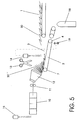
- the control device (14) takes control of the migrating interface (3) and initiates according to predetermined Delay time the lifting device (19) for lowering the first transport route (2), d. H. to open the switch (4).
- the piece of finished wire (30) that has already preceded the Rolling wire runs over the cooling section of the Stelmor plant (1), while the crimp turns (30 '') when entering the Switch (4) deflected downwards and on the mandrel (18) already collected in mini bundles as described above or for example, be shredded into scrap.
- Figure 4 shows the device at the moment Operating state in which the control device (15) End of the roller core (20) detected and a signal with the Triggers signal line (21) to activate the scissors (13). This instantly separates the rolled wire or the finished wire (30) at the interface (3) in finished wire (30) and one in The remaining part of given length.
- Figure 5 shows the device at the moment Operating state in which the counter (14) Interface (3) shortly before the end of the transport route (2) detected and with a predetermined delay opening the switch (4) by folding down the transport route (2) using the Lifting device (19) causes.
- This will - according to Representation in FIG. 6 - the cramp turns (30 ") below the level of the Stelmor facility (1) or one comparable wire winding transport system distracted, during the finished wire (30) - now after cutting off Front (30 ') - and Hinterschopfwinditch (30 ”) - over the Stelmor plant (1) or a comparable one Wire winding transport system is promoted.
- the Hinterschopfwindened (30 '') as before according to FIG. 2 the front crimp turns (30 ') are derived downwards and occasionally collected on the collecting mandrel (18) into mini bundles or shredded into scrap parts in a chopper.
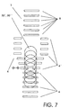
- FIG. 7 shows the formation of a switch (4) on Starting area of the Stelmor plant (1) or one comparable wire winding transport system in the form of a Arrangement of laterally displaceable stub rollers (6).
- the open sale of the stub rollers (6 ') shown the wire windings (30 ') according to FIGS. 1 and 2, respectively (30 '') according to FIGS. 5 and 6 through the switch (4) below.
- the measures and configurations according to the invention are not to those shown in the drawing figures Embodiments limited.
- Possible variations of the Device according to the invention can consist in that for example, the separator (13), the execution of the Switch (4) or the collecting device with the mandrel (18) or the monitoring devices (14, 15) in a different type and Are trained.
- the acceleration more separate Turns or the delay of the subsequent turns can by means of variable roller table speeds or by means of separate devices, such as grippers, Chains, transport fingers.
- the respective constructive Design is in line with special designs or uses or problems to the specialist optional.
Landscapes
- Engineering & Computer Science (AREA)
- Mechanical Engineering (AREA)
- Winding, Rewinding, Material Storage Devices (AREA)
- Filamentary Materials, Packages, And Safety Devices Therefor (AREA)
- Forwarding And Storing Of Filamentary Material (AREA)
- Metal Rolling (AREA)
- Electric Cable Installation (AREA)
- Coiling Of Filamentary Materials In General (AREA)
- Electrical Discharge Machining, Electrochemical Machining, And Combined Machining (AREA)
Claims (7)
- Procédé pour sectionner et évacuer des spires de fil non réfrigérées dont les dimensions ne correspondent pas aux dimensions tolérées et qui sont situées au début et à la fin d'une barre (20) transportée sur un Stelmor (1) ou sur un système transporteur de spires de fil comparable selon lequel on compte un nombre de spires antérieures de la barre (20) et on détache du fil fini (30) ces chutes de spires antérieures (30') après un nombre donné de spires (30'), ces chutes de spires antérieures (30') sectionnées étant déviées vers le bas hors du plan du Stelmor (1) ou d'un système transporteur de spires de fil comparable et évacuées lors de leur passage par un poste d'aiguillage (4) ouvert prévu à la fin du premier trajet de déplacement (2) tandis que le fil fini (30) continue son cheminement dans le Stelmor (1) après fermeture du poste d'aiguillage (4), caractérisé par les étapes de travail suivantes :sur un premier trajet de déplacement (2) limité, les chutes de spires antérieures (30') sectionnées subissent une accélération alors que le fil fini (30) est freiné de sorte que la zone de coupe (3) est élargie pendant le transport etles chutes de spires antérieures (30') sectionnées et évacuées sont recueillies sur un mandrin (18) sous forme de couronnes de fil miniatures en dessous du Stelmor (1) ou d'un système transporteur de spires de fil comparable ou bien elles sont acheminées vers une hacheuse où elles sont hachées menu.
- Procédé selon la revendication 1, caractérisé en ceque l'extrémité arrière de la barre (20) est surveillée et sectionnée, formant les chutes arrières (30"), lorsqu'une longueur résiduelle donnée est atteinte, etque le fil fini (30) restant, dont on a coupé les chutes postérieures (30"), subit une accélération tandis que les spires postérieures (30") sont freinées sur le trajet de déplacement (2) de sorte que la zone de coupe (3) est élargie pendant le transport etque, en entrant dans le poste d'aiguillage (4) ouvert situé en fin de trajet de déplacement (2), les chutes de spires postérieures (30") sectionnées sont déviées vers le bas hors du plan du Stelmor (1) ou d'un système transporteur de spires de fil comparable et transférées en dessous du Stelmor (1) ou d'un système transporteur de spires de fil comparable où elles sont recueillies sur un mandrin (18) sous forme de couronnes de fil miniatures ou acheminées vers une hacheuse où elles sont hachées menu.
- Procédé selon la revendication 1 ou 2, caractérisé en ce que, pour l'ouvrir, le premier trajet de déplacement (2), conformé en forme de poste d'aiguillage (4), est rabattu diagonalement vers le bas hors du plan de transport et que, pour le fermer, il est relevé dans le plan de transport ou bien que le segment qui suit est relevé diagonalement hors du plan de transport pour l'ouvrir et est rabattu dans le plan de transport pour le fermer.
- Procédé selon la revendication 1 ou 2, caractérisé en ce que des galets tronqués (6, 6'), conformés en forme de poste d'aiguillage (4) et susceptibles d'être déplacés de chaque côté transversalement par rapport au sens de déplacement, sont écartés pour les ouvrir et réunis pour les refermer.
- Procédé selon une ou plusieurs des revendications 1 à 4, caractérisé en ce que le poste d'aiguillage (4) est ouvert au moment du sectionnement en vue d'évacuer les chutes de spires antérieures (30') et est refermé tout juste avant que la zone de coupe (3) n'arrive à la fin du trajet de déplacement (2).
- Procédé selon une ou plusieurs des revendications 1 à 5, caractérisé en ce que le sectionnement des chutes de spires postérieures (30") est effectué à l'instant même où l'extrémité arrière de la barre (20), qui fait l'objet d'une surveillance optique ou magnétique, atteint une position prédéterminée, par exemple dans la région du bloc finisseur de fil (10).
- Dispositif pour sectionner et évacuer des chutes antérieures (30') ou postérieures (30") de spires de fil non réfrigérées dont les dimensions ne correspondent pas aux dimensions tolérées et qui sont situées au début et à la fin du fil fini (30) d'une barre (20) transportée sur un Stelmor (1) ou sur un système transporteur de spires de fil comparable, comprenant un bloc finisseur de fil (10) muni d'un circuit d'attaque (11) monté en aval, d'un dispositif de pose des spires (12) et de cisailles (13) ainsi qu'une ligne de refroidissement sous forme de Stelmor (1) ou d'un système transporteur de spires de fil comparable monté en aval avec un premier trajet de déplacement (2) pourvu d'un segment à rouleaux et faisant office de poste d'aiguillage terminal (4), notamment pour mettre en oeuvre le procédé selon l'une quelconque des revendications précédentes, caractérisé en ce quele premier trajet de déplacement (2) possède des moyens destinés à augmenter ou à réduire la vitesse de déplacement, par exemple des moteurs réglables,un organe (15) destiné à surveiller la position imposée du début ou de la fin de la barre (20) en amont ou à l'intérieur du bloc finisseur de fil (10) est associé au bloc finisseur de fil (10),le premier trajet de déplacement (2) possède, en aval des cisailles (13) dans le sens du déplacement, un organe (14) destiné à surveiller de façon contrôlée un nombre imposé de spires de fil (30 et 30' respectivement) ainsi que la position d'une zone de coupe (3) cheminant pendant le transport, ledit organe (14) comportant des moyens servant à la fois à contrôler les cisailles (13) et à ouvrir et fermer le poste d'aiguillage (4),un agencement de galets tronqués (6, 6'), susceptibles de se déplacer latéralement de chaque côté transversalement par rapport au sens de déplacement, ledit agencement étant conformé en forme de poste d'aiguillage (4), est prévu à la fin du premier trajet de déplacement (2) ou dans la zone de raccordement du Stelmor (1) ou d'un système transporteur de spires de fil comparable.
Applications Claiming Priority (2)
| Application Number | Priority Date | Filing Date | Title |
|---|---|---|---|
| DE19717770 | 1997-04-26 | ||
| DE19717770A DE19717770A1 (de) | 1997-04-26 | 1997-04-26 | Verfahren und Vorrichtung zum Abtrennen und Abtransportieren ungekühlter und nicht toleranzhaltiger Drahtwindungen |
Publications (3)
| Publication Number | Publication Date |
|---|---|
| EP0873801A2 EP0873801A2 (fr) | 1998-10-28 |
| EP0873801A3 EP0873801A3 (fr) | 2001-05-02 |
| EP0873801B1 true EP0873801B1 (fr) | 2004-06-02 |
Family
ID=7827895
Family Applications (1)
| Application Number | Title | Priority Date | Filing Date |
|---|---|---|---|
| EP98106999A Expired - Lifetime EP0873801B1 (fr) | 1997-04-26 | 1998-04-17 | Procédé et dispositif de sectionnement et transport de spires de fil non-refroidi et non-conformant aux tolerances |
Country Status (5)
| Country | Link |
|---|---|
| US (1) | US5988551A (fr) |
| EP (1) | EP0873801B1 (fr) |
| JP (1) | JPH1177137A (fr) |
| AT (1) | ATE268230T1 (fr) |
| DE (2) | DE19717770A1 (fr) |
Families Citing this family (5)
| Publication number | Priority date | Publication date | Assignee | Title |
|---|---|---|---|---|
| CN1077486C (zh) * | 1999-06-24 | 2002-01-09 | 唐基斌 | 木质压花板拉伸模具 |
| US6833392B1 (en) * | 1999-11-10 | 2004-12-21 | Lawrence A. Acquarulo, Jr. | Optimizing nano-filler performance in polymers |
| KR101253827B1 (ko) * | 2010-09-10 | 2013-04-12 | 주식회사 포스코 | 선재코일 냉각 방법 및 장치 |
| CN102825074A (zh) * | 2012-09-14 | 2012-12-19 | 南京钢铁股份有限公司 | 一种胎圈钢丝用盘条的控制冷却工艺 |
| KR101746991B1 (ko) * | 2015-12-24 | 2017-06-14 | 주식회사 포스코 | 소재 냉각영역 검출 장치 및 선재 냉각영역 검출 방법 |
Family Cites Families (10)
| Publication number | Priority date | Publication date | Assignee | Title |
|---|---|---|---|---|
| US3452785A (en) * | 1965-12-07 | 1969-07-01 | David William Mclean | Apparatus for depositing and conveying rod rings in sequence with rod forming means |
| DE3029229A1 (de) * | 1980-08-01 | 1982-04-01 | Moeller & Neumann Gmbh, 6670 St Ingbert | Vorrichtung zur herstellung von stahldraht mit vollstaendig angelassener martinsitschicht |
| CH677652A5 (fr) * | 1989-03-07 | 1991-06-14 | Grapha Holding Ag | |
| US5066430A (en) * | 1989-03-20 | 1991-11-19 | E. I. Du Pont De Nemours And Company | Process for centrifugally spinning pitch carbon fibers |
| DE3919836A1 (de) * | 1989-04-26 | 1990-10-31 | Hamburger Stahlwerke Gmbh | Verfahren und anlage zum coupieren der anfangswindungen und/oder endwindungen eines drahtbundes |
| DE4035192A1 (de) * | 1990-11-06 | 1992-05-07 | Thaelmann Schwermaschbau Veb | Vorrichtung zum schopfen der anfangs- und endwindungen eines drahtwindungsstranges |
| DE4106491A1 (de) * | 1991-03-01 | 1992-09-03 | Schloemann Siemag Ag | Anlage mit einem bundbilde- und transportsystem fuer draht oder feinstahl, insbesondere fuer hohe bundgewichte |
| DE4109201A1 (de) * | 1991-03-18 | 1992-09-24 | Thaelmann Schwermaschbau Veb | Vorrichtung zum transportieren und schopfen einer walzader |
| DE4117906C2 (de) * | 1991-05-31 | 1994-01-05 | Andreas Kubicek | Verfahren und Vorrichtungen zur automatischen Handhabung von Walzdraht in Drahtwalzwerken |
| JP2757895B2 (ja) * | 1993-03-19 | 1998-05-25 | スケット・シュヴェルマシイネンバウ・マークデブルク・ゲゼルシャフト・ミト・ベシュレンクテル・ハフツング | 巻線を分離するための方法および装置 |
-
1997
- 1997-04-26 DE DE19717770A patent/DE19717770A1/de not_active Withdrawn
-
1998
- 1998-04-17 DE DE59811494T patent/DE59811494D1/de not_active Expired - Lifetime
- 1998-04-17 EP EP98106999A patent/EP0873801B1/fr not_active Expired - Lifetime
- 1998-04-17 AT AT98106999T patent/ATE268230T1/de active
- 1998-04-23 US US09/065,315 patent/US5988551A/en not_active Expired - Lifetime
- 1998-04-24 JP JP10115555A patent/JPH1177137A/ja not_active Withdrawn
Also Published As
| Publication number | Publication date |
|---|---|
| EP0873801A2 (fr) | 1998-10-28 |
| JPH1177137A (ja) | 1999-03-23 |
| ATE268230T1 (de) | 2004-06-15 |
| US5988551A (en) | 1999-11-23 |
| DE19717770A1 (de) | 1998-10-29 |
| DE59811494D1 (de) | 2004-07-08 |
| EP0873801A3 (fr) | 2001-05-02 |
Similar Documents
| Publication | Publication Date | Title |
|---|---|---|
| EP0909255B1 (fr) | Procede pour changer automatiquement des bobines de fil et dispositif de bobinage avec systeme de changement de bobine | |
| EP3507030B1 (fr) | Installation de production pouvant fonctionner en continu et procédé permettant de faire fonctionner une installation de production en cas de défaillance | |
| DE2102684C3 (de) | Vorrichtung zum Durchtrennen von Walzdraht | |
| DE602004001281T2 (de) | Verfahren und Vorrichtung zum Abbremsen und zur vorübergehenden Speicherung warmgewalzter Produkte | |
| DE2838155C3 (de) | Förderer zum Transportieren von Drahtwindungen | |
| DE19717770A1 (de) | Verfahren und Vorrichtung zum Abtrennen und Abtransportieren ungekühlter und nicht toleranzhaltiger Drahtwindungen | |
| DE2915716C2 (de) | Verfahren zur Beseitigung des Vorder- und Hinterabschnitts von Walzdraht und Vorrichtung zur Durchführung des Verfahrens | |
| DE3116089A1 (de) | "vorrichtung zum unterteilen von drahwindungsstraengen im schacht einer bundsammelstation" | |
| EP0394672B1 (fr) | Procédé et appareil à couper les spires en tête et/ou les spires traînantes d'une bobine de fil | |
| DE2143449C3 (de) | Vorrichtung zum Trennen eines Drahtwindungsstranges in einer Bundbildestation | |
| DE4109201A1 (de) | Vorrichtung zum transportieren und schopfen einer walzader | |
| EP4417332B1 (fr) | Système d'élimination de ferraille, ligne de production de bande métallique et procédé d'élimination de ferraille | |
| DE19652089A1 (de) | Verfahren und Vorrichtung zum Abtrennen ungekühlter und nicht toleranzhaltiger Drahtwindungen vom Anfang und Ende einer über eine Stelmor-Anlage transportierten Walzader | |
| DE2652958A1 (de) | Einrichtung zur vorbereitung des trennschnittes bei walzdraht | |
| WO2005023447A1 (fr) | Procede et dispositif d'extrusion de profiles extrudes courbes | |
| DE1527867B2 (de) | Wahlweise im edenborn oder garrett system arbeitender haspel fuer walzdraht | |
| DE60004610T2 (de) | Verfahren und Anlage zum Walzen von mehreren Knüppeln, die aus einem einer Walzstrasse vorgeordneten Knüppelheizofen zugeführt werden | |
| DE2212944B2 (de) | Verfahren und vorrichtung zur bildung von walzdrahtbunden | |
| DE4320736A1 (de) | Verfahren und Vorrichtung zum schonenden Abkühlen von zu Stäben warmgewalzten Spezial- und Edelstählen | |
| DE4117906A1 (de) | Verfahren und vorrichtungen zur automatischen handhabung von walzdraht in drahtwalzwerken | |
| DE4035192A1 (de) | Vorrichtung zum schopfen der anfangs- und endwindungen eines drahtwindungsstranges | |
| EP4368308A1 (fr) | Procédé et système d'enroulement | |
| DE2461303A1 (de) | Walzwerk zum kaltwalzen von rohren | |
| DE3206211A1 (de) | Vorrichtung zum bilden von walzdraht- und schrottbunden | |
| DE2150420A1 (de) | Vorrichtung zum unterteilen eines drahtwindungsstranges in einer bundbildestation |
Legal Events
| Date | Code | Title | Description |
|---|---|---|---|
| PUAI | Public reference made under article 153(3) epc to a published international application that has entered the european phase |
Free format text: ORIGINAL CODE: 0009012 |
|
| 17P | Request for examination filed |
Effective date: 19980417 |
|
| AK | Designated contracting states |
Kind code of ref document: A2 Designated state(s): AT DE IT SE |
|
| AX | Request for extension of the european patent |
Free format text: AL;LT;LV;MK;RO;SI |
|
| RAP1 | Party data changed (applicant data changed or rights of an application transferred) |
Owner name: SMS DEMAG AG |
|
| PUAL | Search report despatched |
Free format text: ORIGINAL CODE: 0009013 |
|
| AK | Designated contracting states |
Kind code of ref document: A3 Designated state(s): AT BE CH CY DE DK ES FI FR GB GR IE IT LI LU MC NL PT SE |
|
| AX | Request for extension of the european patent |
Free format text: AL;LT;LV;MK;RO;SI |
|
| AKX | Designation fees paid |
Free format text: AT DE IT SE |
|
| 17Q | First examination report despatched |
Effective date: 20030424 |
|
| GRAP | Despatch of communication of intention to grant a patent |
Free format text: ORIGINAL CODE: EPIDOSNIGR1 |
|
| GRAS | Grant fee paid |
Free format text: ORIGINAL CODE: EPIDOSNIGR3 |
|
| GRAA | (expected) grant |
Free format text: ORIGINAL CODE: 0009210 |
|
| AK | Designated contracting states |
Kind code of ref document: B1 Designated state(s): AT DE IT SE |
|
| REG | Reference to a national code |
Ref country code: SE Ref legal event code: TRGR |
|
| REF | Corresponds to: |
Ref document number: 59811494 Country of ref document: DE Date of ref document: 20040708 Kind code of ref document: P |
|
| PLBE | No opposition filed within time limit |
Free format text: ORIGINAL CODE: 0009261 |
|
| STAA | Information on the status of an ep patent application or granted ep patent |
Free format text: STATUS: NO OPPOSITION FILED WITHIN TIME LIMIT |
|
| 26N | No opposition filed |
Effective date: 20050303 |
|
| PGFP | Annual fee paid to national office [announced via postgrant information from national office to epo] |
Ref country code: SE Payment date: 20140418 Year of fee payment: 17 Ref country code: DE Payment date: 20140418 Year of fee payment: 17 Ref country code: AT Payment date: 20140411 Year of fee payment: 17 Ref country code: IT Payment date: 20140429 Year of fee payment: 17 |
|
| REG | Reference to a national code |
Ref country code: DE Ref legal event code: R082 Ref document number: 59811494 Country of ref document: DE Representative=s name: HEMMERICH & KOLLEGEN, DE Ref country code: DE Ref legal event code: R081 Ref document number: 59811494 Country of ref document: DE Owner name: SMS GROUP GMBH, DE Free format text: FORMER OWNER: SMS SIEMAG AKTIENGESELLSCHAFT, 40237 DUESSELDORF, DE |
|
| REG | Reference to a national code |
Ref country code: DE Ref legal event code: R119 Ref document number: 59811494 Country of ref document: DE |
|
| REG | Reference to a national code |
Ref country code: AT Ref legal event code: MM01 Ref document number: 268230 Country of ref document: AT Kind code of ref document: T Effective date: 20150417 Ref country code: SE Ref legal event code: EUG |
|
| PG25 | Lapsed in a contracting state [announced via postgrant information from national office to epo] |
Ref country code: DE Free format text: LAPSE BECAUSE OF NON-PAYMENT OF DUE FEES Effective date: 20151103 Ref country code: IT Free format text: LAPSE BECAUSE OF NON-PAYMENT OF DUE FEES Effective date: 20150417 |
|
| PG25 | Lapsed in a contracting state [announced via postgrant information from national office to epo] |
Ref country code: SE Free format text: LAPSE BECAUSE OF NON-PAYMENT OF DUE FEES Effective date: 20150418 Ref country code: AT Free format text: LAPSE BECAUSE OF NON-PAYMENT OF DUE FEES Effective date: 20150417 |