EP0874181A2 - Joint métallique avec bourrelet ayant subi un traitement thermique local - Google Patents
Joint métallique avec bourrelet ayant subi un traitement thermique local Download PDFInfo
- Publication number
- EP0874181A2 EP0874181A2 EP98105185A EP98105185A EP0874181A2 EP 0874181 A2 EP0874181 A2 EP 0874181A2 EP 98105185 A EP98105185 A EP 98105185A EP 98105185 A EP98105185 A EP 98105185A EP 0874181 A2 EP0874181 A2 EP 0874181A2
- Authority
- EP
- European Patent Office
- Prior art keywords
- bead
- beads
- metal
- metal gasket
- gasket
- Prior art date
- Legal status (The legal status is an assumption and is not a legal conclusion. Google has not performed a legal analysis and makes no representation as to the accuracy of the status listed.)
- Granted
Links
Images
Classifications
-
- F—MECHANICAL ENGINEERING; LIGHTING; HEATING; WEAPONS; BLASTING
- F16—ENGINEERING ELEMENTS AND UNITS; GENERAL MEASURES FOR PRODUCING AND MAINTAINING EFFECTIVE FUNCTIONING OF MACHINES OR INSTALLATIONS; THERMAL INSULATION IN GENERAL
- F16J—PISTONS; CYLINDERS; SEALINGS
- F16J15/00—Sealings
- F16J15/02—Sealings between relatively-stationary surfaces
- F16J15/06—Sealings between relatively-stationary surfaces with solid packing compressed between sealing surfaces
- F16J15/08—Sealings between relatively-stationary surfaces with solid packing compressed between sealing surfaces with exclusively metal packing
- F16J15/0818—Flat gaskets
-
- F—MECHANICAL ENGINEERING; LIGHTING; HEATING; WEAPONS; BLASTING
- F16—ENGINEERING ELEMENTS AND UNITS; GENERAL MEASURES FOR PRODUCING AND MAINTAINING EFFECTIVE FUNCTIONING OF MACHINES OR INSTALLATIONS; THERMAL INSULATION IN GENERAL
- F16J—PISTONS; CYLINDERS; SEALINGS
- F16J15/00—Sealings
- F16J15/02—Sealings between relatively-stationary surfaces
- F16J15/06—Sealings between relatively-stationary surfaces with solid packing compressed between sealing surfaces
- F16J15/08—Sealings between relatively-stationary surfaces with solid packing compressed between sealing surfaces with exclusively metal packing
- F16J15/0818—Flat gaskets
- F16J2015/085—Flat gaskets without fold over
Definitions
- the present invention relates to a metal gasket with a locally heat-treated bead used for an internal combustion engine.
- An internal combustion engine has been developed to provide high power and light weight. As a result, high pressure and high temperature are applied to the engine. Since a metal gasket is strong against high pressure and high temperature, the metal gasket has been widely used.
- the various holes are formed as stated above.
- bolts for tightening the cylinder head and the cylinder block are arranged around the cylinder bores to provide surface pressures around the cylinder bores as equal as possible.
- the pressures for other holes are less than those of the cylinder bores.
- the highest surface pressures are formed around the cylinder bores to securely seal therearound.
- the beads are formed around the various holes, in view of the required arrangement of the surface pressures on the gasket, the beads around the cylinder bores are formed to provide the surface pressures higher than those of the other holes.
- the height and/or width of the bead is changed.
- the surface pressure of the bead increases, and as the width of the bead decreases, the surface pressure of the bead increases.
- the surface pressure of the bead is changed, as well.
- the metal gaskets and metal laminate gaskets have been designed and prepared in view of the above, for example, U.S. Patent No. 5,536,024.
- the width and/or height of the beads must be changed.
- the surface pressure of the bead can be adjusted by changing the width and/or height of the bead, the surface pressure can not be precisely adjusted by changing the width and/or height of the bead.
- an object of the invention is to provide a metal gasket with a bead, wherein the surface pressure of the bead can be changed easily without changing the width and height.
- Another object of the invention is to provide a metal gasket as stated above, wherein the surface pressures of the beads on one metal plate can be changed easily.
- a further object of the invention is to provide a metal gasket as stated above, wherein the arrangement of the beads with different surface pressures can be made easily.
- a metal gasket of the invention is used for an internal combustion engine, especially for a cylinder head gasket.
- the gasket is formed of a metal plate for constituting the metal gasket, and a first bead formed on the metal plate.
- the first bead has a portion with a hardness different from that of the metal plate by a heat treatment, i.e. heating the first bead locally and then cooling the same.
- the first bead may be heat-treated partly or entirely.
- the metal plate is formed as usual by cutting holes, such as cylinder bores, water holes, oil holes, bolt holes and so on, and forming beads around the required holes, such as cylinder bores, water holes and oil holes.
- the beads e.g. first beads
- the beads are locally heated by laser beam or high frequency waves, and is cooled immediately.
- the hardness of the metal plate at the beads is only increased, so that the surface pressures of the beads when the beads are compressed are increased.
- the metal plate may further include a second bead, which is not heat-treated.
- a second bead which is not heat-treated.
- the first bead is formed around the cylinder bore, and the second bead is formed around a fluid hole, so that the first bead provides the surface pressure greater than that of the second bead when the gasket is tightened.
- the bead In order to increase the surface pressure of the bead by the heat treatment, after the bead is heated, the bead is cooled immediately. However, after a bead is heated, the bead may be cooled slowly to provide a weak spring constant. In the invention, the spring constant of a bead can be increased or decreased, as required.
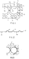
- a gasket G is a cylinder head gasket for an internal combustion engine, and includes a plurality of cylinder bores Hc, water holes Hw, oil holes Ho, bolt holes Hb, push rod holes Hp and so on, as in the conventional gasket.
- the gasket G is formed of one metal plate 10 extending throughout the entire area to be sealed between a cylinder head and a cylinder block (both not shown).
- the metal plate 10 includes beads 11 around the cylinder bores Hc, beads 12 around the water holes Hw, beads 13 around the oil holes Ho, and beads 14 around the push rod holes Hp.
- the beads 12, 13, 14 have the same height, but the bead 11 is higher than the beads 12, 13, 14 to provide high surface pressure when the gasket is tightened.
- the plate 10 is cut along the outer shape of the engine, and also, various holes, i.e. cylinder bores Hc, water holes Hw, oil holes Ho, bolt holes Hb, push rod holes Hp and so on, are formed. Then, the beads 11, 12, 13, 14 are prepared to surround the cylinder bores Hc, water holes Hw, oil holes Ho and push rod holes Hp.
- various holes i.e. cylinder bores Hc, water holes Hw, oil holes Ho, bolt holes Hb, push rod holes Hp and so on.
- the beads 11 around the cylinder bores Hc and their vicinities are heated locally by a laser beam, and then cooled immediately. Accordingly, the hardness of the plate 10 at the beads 11 is locally increased.
- the beads 11 may be locally heated by other means, such as high frequency waves.
- the spring constant of the bead 11 is increased as well.
- the bead with the heat treatment can provide surface pressure greater than the bead without heat treatment.
- the sizes of the beads 11 are greater than those of the other beads 12, 13, 14.
- the beads 11 may have the same sizes as in the other beads. In this case, since the beads 11 have the heat treatment, the beads 11 can provide surface pressures greater than those of the other beads.
- the bead 11 is cooled immediately.
- the bead 11 may be cooled gradually to lower the hardness of the plate at the bead.
- the beads 11 may not be heat-treated, and instead, the other beads 12, 13, 14 may have heat-treatment to lower the hardness of the beads. Namely, after the beads 12, 13, 14 are heated, the beads are gradually cooled to lower the hardness of the beads.
- all the beads formed in the metal plate may be locally heated to increase the hardness of the beads.
- the heat treatment of the beads may be determined based on the arrangement of the beads, quality of the plate, and so on.
- a part 11a' of a bead 11' may be heat-treated without heat-treating a part 11b'. Namely, one bead 11' has the heat-treated part 11a' and non-heat-treated part 11b'. As a result, a surface pressure of the part 11a' can be only increased.
- the part 11a' may be located at the end portions of the gasket to support high tightening pressure thereat.
- the gasket G is formed of one metal plate 10.
- the metal plate 10 may be combined with one or more metal plates to constitute a metal laminate gasket.
- the desired bead is entirely or partly heat-treated to change the hardness of the bead, it is possible to precisely set the surface pressure of the bead.
- the arrangement of the surface pressures of the beads can be determined.
- the surface pressure of the bead can be easily adjusted while considering the width and height of the bead.
Landscapes
- Engineering & Computer Science (AREA)
- General Engineering & Computer Science (AREA)
- Mechanical Engineering (AREA)
- Gasket Seals (AREA)
Applications Claiming Priority (2)
| Application Number | Priority Date | Filing Date | Title |
|---|---|---|---|
| US840607 | 1997-04-24 | ||
| US08/840,607 US5906376A (en) | 1997-04-24 | 1997-04-24 | Metal gasket with locally heated-treating bead |
Publications (3)
| Publication Number | Publication Date |
|---|---|
| EP0874181A2 true EP0874181A2 (fr) | 1998-10-28 |
| EP0874181A3 EP0874181A3 (fr) | 1999-10-13 |
| EP0874181B1 EP0874181B1 (fr) | 2004-10-27 |
Family
ID=25282789
Family Applications (1)
| Application Number | Title | Priority Date | Filing Date |
|---|---|---|---|
| EP98105185A Expired - Lifetime EP0874181B1 (fr) | 1997-04-24 | 1998-03-23 | Joint métallique avec bourrelet ayant subi un traitement thermique local |
Country Status (4)
| Country | Link |
|---|---|
| US (1) | US5906376A (fr) |
| EP (1) | EP0874181B1 (fr) |
| JP (1) | JP2981202B2 (fr) |
| DE (1) | DE69827190T2 (fr) |
Families Citing this family (14)
| Publication number | Priority date | Publication date | Assignee | Title |
|---|---|---|---|---|
| US6257591B1 (en) * | 1996-12-16 | 2001-07-10 | Kokusan Parts Industry Co., Ltd. | Metal gasket and process for manufacturing the same |
| JP4032270B2 (ja) * | 1998-09-18 | 2008-01-16 | 大豊工業株式会社 | シリンダヘッドガスケット |
| JP3177841B2 (ja) | 1999-09-08 | 2001-06-18 | 石川ガスケット株式会社 | シリンダヘッドガスケット |
| KR100320548B1 (ko) * | 1999-11-17 | 2002-01-16 | 성태홍 | 가스켓 및 그 제조방법 |
| US6237557B1 (en) | 2000-04-28 | 2001-05-29 | Dana Corporation | Integrated push rod locator in cylinder head gasket |
| DE10114598A1 (de) * | 2001-03-23 | 2002-10-02 | Aventis Pharma Gmbh | CIP-gerechte Ausführung einer Horizontalzentrifuge mit Vollmanteltrommel |
| JP2003035202A (ja) * | 2001-07-19 | 2003-02-07 | Ishikawa Gasket Co Ltd | ヘッドガスケット |
| JP2003035363A (ja) * | 2001-07-23 | 2003-02-07 | Ishikawa Gasket Co Ltd | シリンダヘッドガスケット |
| DE102005003017B4 (de) * | 2004-01-23 | 2019-10-24 | Koichi Hatamura | Metalldichtung |
| US7287758B2 (en) * | 2005-11-08 | 2007-10-30 | Dana Corporation | Cylinder head gasket with an oil drainback tube fastener |
| KR101412871B1 (ko) * | 2008-08-05 | 2014-06-27 | 현대자동차주식회사 | 차량용 피스톤 및 그 제조방법 |
| JP5913533B1 (ja) * | 2014-11-13 | 2016-04-27 | 石川ガスケット株式会社 | ガスケット及びガスケットの製造方法 |
| WO2017090702A1 (fr) * | 2015-11-27 | 2017-06-01 | Nok株式会社 | Joint d'étanchéité métallique |
| EP3885566A4 (fr) * | 2019-03-25 | 2022-08-10 | NOK Corporation | Joint d'étanchéité |
Citations (1)
| Publication number | Priority date | Publication date | Assignee | Title |
|---|---|---|---|---|
| US5536024A (en) | 1993-12-01 | 1996-07-16 | Ishikawa Gasket Co., Ltd. | Metal gasket having sealing beads with different width and height |
Family Cites Families (9)
| Publication number | Priority date | Publication date | Assignee | Title |
|---|---|---|---|---|
| US4480844A (en) * | 1982-12-20 | 1984-11-06 | Dana Corporation | Cylinder head gasket with variable thickness fire ring |
| US4834399A (en) * | 1986-11-10 | 1989-05-30 | Ishikawa Gasket Co., Ltd. | Steel laminate gasket |
| EP0486255B1 (fr) * | 1990-11-14 | 1996-10-23 | NIPPON GASKET COMPANY Ltd. | Joint d'étanchéité métallique |
| US5344165A (en) * | 1991-05-13 | 1994-09-06 | Ishikawa Gasket Co., Ltd. | Metal gasket having fluid hole sealing device with different spring constant |
| US5454574A (en) * | 1992-12-18 | 1995-10-03 | Dana Corporation | Composite powdered metal combustion seal ring |
| JPH07253162A (ja) * | 1994-06-30 | 1995-10-03 | Nippon Riikuresu Kogyo Kk | メタルガスケット |
| DE4440503C1 (de) * | 1994-11-12 | 1996-03-28 | Payen Goetze Gmbh | Metallische Flachdichtung |
| US5669614A (en) * | 1996-07-02 | 1997-09-23 | Ishikawa Gasket Co., Ltd. | Metal gasket having bead with inclined end portion |
| DE19708970B4 (de) * | 1997-03-05 | 2009-09-24 | Reinz-Dichtungs-Gmbh | Metallische Flachdichtung |
-
1997
- 1997-04-24 US US08/840,607 patent/US5906376A/en not_active Expired - Fee Related
-
1998
- 1998-03-23 DE DE69827190T patent/DE69827190T2/de not_active Expired - Fee Related
- 1998-03-23 EP EP98105185A patent/EP0874181B1/fr not_active Expired - Lifetime
- 1998-04-22 JP JP10112351A patent/JP2981202B2/ja not_active Expired - Fee Related
Patent Citations (1)
| Publication number | Priority date | Publication date | Assignee | Title |
|---|---|---|---|---|
| US5536024A (en) | 1993-12-01 | 1996-07-16 | Ishikawa Gasket Co., Ltd. | Metal gasket having sealing beads with different width and height |
Also Published As
| Publication number | Publication date |
|---|---|
| JPH1122827A (ja) | 1999-01-26 |
| DE69827190D1 (de) | 2004-12-02 |
| EP0874181A3 (fr) | 1999-10-13 |
| JP2981202B2 (ja) | 1999-11-22 |
| US5906376A (en) | 1999-05-25 |
| EP0874181B1 (fr) | 2004-10-27 |
| DE69827190T2 (de) | 2005-03-17 |
Similar Documents
| Publication | Publication Date | Title |
|---|---|---|
| US5906376A (en) | Metal gasket with locally heated-treating bead | |
| EP0633396B1 (fr) | Joint d'étanchéité métallique | |
| US6186513B1 (en) | Method of forming gasket with annular sealing projection and groove | |
| US5294135A (en) | Metal gasket and production method thereof | |
| JP2844501B2 (ja) | 金属製ガスケットおよびその製造方法 | |
| EP0809051B1 (fr) | Joint métallique multicouches avec bourrelets partiels | |
| US5769430A (en) | Metal gasket with bead and thermal sprayed layer thereof | |
| EP0494801B1 (fr) | Moteur à combustion interne et plaque d'étanchéité métallique pour utilisation dans ce moteur | |
| US5536024A (en) | Metal gasket having sealing beads with different width and height | |
| US5979907A (en) | Metal gasket with edge support shim | |
| EP0430163B1 (fr) | Dispositif d'étanchéité en acier laminé avec des éléments d'étanchéité principaux et auxiliaires | |
| US6168166B1 (en) | Metal gasket with two half beads | |
| EP0816722B1 (fr) | Joint métallique présentant une nervure dont la portion finale est inclinée | |
| EP0816724B1 (fr) | Joint métallique comportant une nervure périphérique | |
| US5879012A (en) | Metal gasket with reduced thickness bead | |
| US6439579B2 (en) | Laminated gasket | |
| US6428016B1 (en) | Metal cylinder head gasket with compressibility adjusting slits | |
| US5934682A (en) | Head gasket with preflattened wire rings and method of making and using same | |
| US5272808A (en) | Method of manufacturing a cylinder head gasket | |
| JP2996189B2 (ja) | メタルガスケットの製造方法 | |
| US7108268B2 (en) | Metal laminate gasket | |
| JP2973099B2 (ja) | ヘッドガスケット | |
| JPH07224938A (ja) | 金属製ガスケット | |
| JP2891229B2 (ja) | メタルガスケット及びその製造方法 | |
| US20050167929A1 (en) | Cylinder head gasket |
Legal Events
| Date | Code | Title | Description |
|---|---|---|---|
| PUAI | Public reference made under article 153(3) epc to a published international application that has entered the european phase |
Free format text: ORIGINAL CODE: 0009012 |
|
| AK | Designated contracting states |
Kind code of ref document: A2 Designated state(s): DE FR GB IT |
|
| AX | Request for extension of the european patent |
Free format text: AL;LT;LV;MK;RO;SI |
|
| PUAL | Search report despatched |
Free format text: ORIGINAL CODE: 0009013 |
|
| AK | Designated contracting states |
Kind code of ref document: A3 Designated state(s): AT BE CH DE DK ES FI FR GB GR IE IT LI LU MC NL PT SE |
|
| AX | Request for extension of the european patent |
Free format text: AL;LT;LV;MK;RO;SI |
|
| 17P | Request for examination filed |
Effective date: 19991020 |
|
| AKX | Designation fees paid |
Free format text: DE FR GB IT |
|
| 17Q | First examination report despatched |
Effective date: 20021023 |
|
| GRAP | Despatch of communication of intention to grant a patent |
Free format text: ORIGINAL CODE: EPIDOSNIGR1 |
|
| GRAS | Grant fee paid |
Free format text: ORIGINAL CODE: EPIDOSNIGR3 |
|
| GRAA | (expected) grant |
Free format text: ORIGINAL CODE: 0009210 |
|
| AK | Designated contracting states |
Kind code of ref document: B1 Designated state(s): DE FR GB IT |
|
| REG | Reference to a national code |
Ref country code: GB Ref legal event code: FG4D |
|
| REF | Corresponds to: |
Ref document number: 69827190 Country of ref document: DE Date of ref document: 20041202 Kind code of ref document: P |
|
| PGFP | Annual fee paid to national office [announced via postgrant information from national office to epo] |
Ref country code: FR Payment date: 20050308 Year of fee payment: 8 |
|
| PGFP | Annual fee paid to national office [announced via postgrant information from national office to epo] |
Ref country code: DE Payment date: 20050317 Year of fee payment: 8 |
|
| PGFP | Annual fee paid to national office [announced via postgrant information from national office to epo] |
Ref country code: GB Payment date: 20050323 Year of fee payment: 8 |
|
| PLBE | No opposition filed within time limit |
Free format text: ORIGINAL CODE: 0009261 |
|
| STAA | Information on the status of an ep patent application or granted ep patent |
Free format text: STATUS: NO OPPOSITION FILED WITHIN TIME LIMIT |
|
| 26N | No opposition filed |
Effective date: 20050728 |
|
| ET | Fr: translation filed | ||
| PG25 | Lapsed in a contracting state [announced via postgrant information from national office to epo] |
Ref country code: GB Free format text: LAPSE BECAUSE OF NON-PAYMENT OF DUE FEES Effective date: 20060323 |
|
| PGFP | Annual fee paid to national office [announced via postgrant information from national office to epo] |
Ref country code: IT Payment date: 20060331 Year of fee payment: 9 |
|
| PG25 | Lapsed in a contracting state [announced via postgrant information from national office to epo] |
Ref country code: DE Free format text: LAPSE BECAUSE OF NON-PAYMENT OF DUE FEES Effective date: 20061003 |
|
| GBPC | Gb: european patent ceased through non-payment of renewal fee |
Effective date: 20060323 |
|
| REG | Reference to a national code |
Ref country code: FR Ref legal event code: ST Effective date: 20061130 |
|
| PG25 | Lapsed in a contracting state [announced via postgrant information from national office to epo] |
Ref country code: FR Free format text: LAPSE BECAUSE OF NON-PAYMENT OF DUE FEES Effective date: 20060331 |
|
| PG25 | Lapsed in a contracting state [announced via postgrant information from national office to epo] |
Ref country code: IT Free format text: LAPSE BECAUSE OF NON-PAYMENT OF DUE FEES Effective date: 20070323 |