EP0874202B1 - Mit einem elektromagnetischen Ventil vereinigtes Entspannungsventil und dieses verwendender Kältekreislauf - Google Patents
Mit einem elektromagnetischen Ventil vereinigtes Entspannungsventil und dieses verwendender Kältekreislauf Download PDFInfo
- Publication number
- EP0874202B1 EP0874202B1 EP97122936A EP97122936A EP0874202B1 EP 0874202 B1 EP0874202 B1 EP 0874202B1 EP 97122936 A EP97122936 A EP 97122936A EP 97122936 A EP97122936 A EP 97122936A EP 0874202 B1 EP0874202 B1 EP 0874202B1
- Authority
- EP
- European Patent Office
- Prior art keywords
- refrigerant
- pressure
- valve
- valve element
- expansion valve
- Prior art date
- Legal status (The legal status is an assumption and is not a legal conclusion. Google has not performed a legal analysis and makes no representation as to the accuracy of the status listed.)
- Expired - Lifetime
Links
Images


Classifications
-
- B—PERFORMING OPERATIONS; TRANSPORTING
- B60—VEHICLES IN GENERAL
- B60H—ARRANGEMENTS OF HEATING, COOLING, VENTILATING OR OTHER AIR-TREATING DEVICES SPECIALLY ADAPTED FOR PASSENGER OR GOODS SPACES OF VEHICLES
- B60H1/00—Heating, cooling or ventilating devices
- B60H1/32—Cooling devices
- B60H1/3204—Cooling devices using compression
- B60H1/323—Cooling devices using compression characterised by comprising auxiliary or multiple systems, e.g. plurality of evaporators, or by involving auxiliary cooling devices
-
- F—MECHANICAL ENGINEERING; LIGHTING; HEATING; WEAPONS; BLASTING
- F25—REFRIGERATION OR COOLING; COMBINED HEATING AND REFRIGERATION SYSTEMS; HEAT PUMP SYSTEMS; MANUFACTURE OR STORAGE OF ICE; LIQUEFACTION SOLIDIFICATION OF GASES
- F25B—REFRIGERATION MACHINES, PLANTS OR SYSTEMS; COMBINED HEATING AND REFRIGERATION SYSTEMS; HEAT PUMP SYSTEMS
- F25B41/00—Fluid-circulation arrangements
- F25B41/20—Disposition of valves, e.g. of on-off valves or flow control valves
- F25B41/24—Arrangement of shut-off valves for disconnecting a part of the refrigerant cycle, e.g. an outdoor part
-
- F—MECHANICAL ENGINEERING; LIGHTING; HEATING; WEAPONS; BLASTING
- F25—REFRIGERATION OR COOLING; COMBINED HEATING AND REFRIGERATION SYSTEMS; HEAT PUMP SYSTEMS; MANUFACTURE OR STORAGE OF ICE; LIQUEFACTION SOLIDIFICATION OF GASES
- F25B—REFRIGERATION MACHINES, PLANTS OR SYSTEMS; COMBINED HEATING AND REFRIGERATION SYSTEMS; HEAT PUMP SYSTEMS
- F25B41/00—Fluid-circulation arrangements
- F25B41/30—Expansion means; Dispositions thereof
- F25B41/31—Expansion valves
- F25B41/33—Expansion valves with the valve member being actuated by the fluid pressure, e.g. by the pressure of the refrigerant
- F25B41/335—Expansion valves with the valve member being actuated by the fluid pressure, e.g. by the pressure of the refrigerant via diaphragms
-
- F—MECHANICAL ENGINEERING; LIGHTING; HEATING; WEAPONS; BLASTING
- F25—REFRIGERATION OR COOLING; COMBINED HEATING AND REFRIGERATION SYSTEMS; HEAT PUMP SYSTEMS; MANUFACTURE OR STORAGE OF ICE; LIQUEFACTION SOLIDIFICATION OF GASES
- F25B—REFRIGERATION MACHINES, PLANTS OR SYSTEMS; COMBINED HEATING AND REFRIGERATION SYSTEMS; HEAT PUMP SYSTEMS
- F25B5/00—Compression machines, plants or systems, with several evaporator circuits, e.g. for varying refrigerating capacity
- F25B5/02—Compression machines, plants or systems, with several evaporator circuits, e.g. for varying refrigerating capacity arranged in parallel
-
- F—MECHANICAL ENGINEERING; LIGHTING; HEATING; WEAPONS; BLASTING
- F25—REFRIGERATION OR COOLING; COMBINED HEATING AND REFRIGERATION SYSTEMS; HEAT PUMP SYSTEMS; MANUFACTURE OR STORAGE OF ICE; LIQUEFACTION SOLIDIFICATION OF GASES
- F25B—REFRIGERATION MACHINES, PLANTS OR SYSTEMS; COMBINED HEATING AND REFRIGERATION SYSTEMS; HEAT PUMP SYSTEMS
- F25B2341/00—Details of ejectors not being used as compression device; Details of flow restrictors or expansion valves
- F25B2341/06—Details of flow restrictors or expansion valves
- F25B2341/068—Expansion valves combined with a sensor
- F25B2341/0683—Expansion valves combined with a sensor the sensor is disposed in the suction line and influenced by the temperature or the pressure of the suction gas
-
- F—MECHANICAL ENGINEERING; LIGHTING; HEATING; WEAPONS; BLASTING
- F25—REFRIGERATION OR COOLING; COMBINED HEATING AND REFRIGERATION SYSTEMS; HEAT PUMP SYSTEMS; MANUFACTURE OR STORAGE OF ICE; LIQUEFACTION SOLIDIFICATION OF GASES
- F25B—REFRIGERATION MACHINES, PLANTS OR SYSTEMS; COMBINED HEATING AND REFRIGERATION SYSTEMS; HEAT PUMP SYSTEMS
- F25B2600/00—Control issues
- F25B2600/25—Control of valves
- F25B2600/2519—On-off valves
Definitions
- the present invention relates to an expansion valve integrated with an electromagnetic valve, in which the electromagnetic valve is disposed at a downstream side of the expansion valve and both are integrated.
- the present invention is suitably employed in, for example, an air conditioning apparatus for a vehicle, which has an air conditioning unit incorporating therein evaporators of a refrigeration cycle, disposed at a front side and a rear side, respectively, in a passenger compartment.
- JP-A-62 041481 discloses an expansion valve integrated with an electromagnetic valve and comprising an expansion valve body having a restriction path for decompressing and expanding refrigerant introduced into the expansion valve body, a first valve element for adjusting an opening degree of said restriction path, and a valve element operating mechanism for moving said first valve element, wherein said electromagnetic valve is integrally assembled in said expansion valve body and includes a second valve element to open and close a uniform pressure passage.
- the electromagnetic valve is connected to the expansion valve in series to switch a flow of the refrigerant into these evaporators.
- the electromagnetic valve is integrated with the expansion valve body so that both of the electromagnetic valve and the expansion valve can be downsized.
- the electromagnetic valve is disposed at a downstream side of the expansion valve, i.e., in a path at a low-pressure side through which gas and liquid two phase refrigerant flows, to reduce the water hammer noise generated when the electromagnetic valve is closed.
- a temperature of the evaporator increases up to an ambient temperature (a temperature of the passenger compartment). Therefore, a temperature of a temperature sensing bulb disposed at a refrigerant outlet side of the evaporator also increases up to the temperature of the passenger compartment.
- a pressure at a low-pressure side of this expansion valve lowers by the refrigerant circulating into the other expansion valve (by an operation of the compressor), with the result that a force in a valve closing direction is applied to a valve body of the expansion valve to fully close the expansion valve.
- an expansion valve is integrated with an electromagnetic valve, which is employed in a refrigeration cycle having evaporators connected in parallel.
- the expansion valve decompresses and expands refrigerant, and the electromagnetic valve opens and closes a refrigeration path of the refrigeration cycle.
- the expansion valve includes an expansion valve body for forming an outer shape of the expansion valve, and the expansion body has an inlet refrigerant path for introducing high-pressure side refrigerant of the refrigeration cycle, a restriction path for decompressing and expanding the refrigerant introduced from the inlet refrigerant path and an outlet refrigerant path for supplying the refrigerant decompressed and expanded in the restriction path.
- the expansion valve includes a first valve element for adjusting an opening degree of the restriction path, and a valve element operating mechanism for moving the first valve element.
- the electromagnetic valve is integrally assembled in the expansion valve body and includes a second valve element disposed to open and close the outlet refrigerant path.
- valve element operating mechanism When the second valve element is closed, the valve element operating mechanism operates based on a refrigerant pressure between the second valve element and the restriction path such that the first valve element is closed.
- the upstream side of the second valve element becomes the high-pressure side pressure by an operation of the refrigerant cycle. Accordingly, the valve element operating mechanism is operated by using the high-pressure side pressure so that the first valve element of the expansion valve can be closed.
- the electromagnetic valve when the electromagnetic valve is then opened, a large amount of the refrigerant does not start to flow suddenly and it is possible to effectively suppress the refrigerant flowing noise or the like generated when the electromagnetic valve is opened. Further, since the electromagnetic valve is disposed in a range of the gas and liquid two phase refrigerant at the downstream side of the first valve element of the expansion valve, it is possible to sufficiently reduce the water hammer noise generated when the electromagnetic valve is closed, as usual.
- the expansion valve body may include a low-pressure refrigerant path through which the refrigerant from the outlet of the evaporator flows, and a temperature sensing rod may be disposed in the expansion valve body to pass through the low-pressure refrigerant path, for sensing a temperature of the refrigerant at the outlet of the evaporator and transmitting a pressure thereof to the first pressure chamber.
- first communication means in the expansion valve body for communicating between the second valve element and the restriction path
- second communication means in the temperature sensing rod for communicating the first communication means with the second pressure chamber. The refrigerant pressure between the second valve element and the restriction path is introduced into the second pressure chamber through the first and second communication means.
- a first pressure chamber may be formed at one side of the pressure responding member to receive pressure corresponding to a temperature of the refrigerant at an outlet of the evaporator, and a second pressure chamber may be formed at the other side of the pressure responding.
- a stopper member disposed in the second pressure chamber to form a third pressure chamber partitioned from the second pressure chamber, and the stopper member moves integrally with the pressure responding member. The refrigerant pressure between the second valve element and the restriction path is introduced into the third pressure chamber, and a refrigerant pressure at a downstream side of the second valve element is introduced into the second pressure chamber.
- the high-pressure side pressure of the refrigeration cycle applying to the upstream side of the electromagnetic valve is applied to the stopper member so that the first valve element of the expansion valve can be closed. Accordingly, it is possible to suppress the refrigerant flowing noise or the like generated when the electromagnetic valve is opened. Further, the high-pressure side pressure of the refrigeration cycle is not applied directly to the pressure responding member when the electromagnetic valve is closed, it is not necessary for the valve element operating mechanism to be structured rigid enough against the high-pressure side pressure of the refrigeration cycle. Therefore, it is possible to manufacture the valve operating mechanism with low cost.
- FIGS. 1 to 5 A first embodiment of the present invention will be described with reference to FIGS. 1 to 5.
- FIG. 1 shows an entire construction in which an expansion valve 14 according to the present invention is employed in a refrigeration cycle.
- the refrigeration cycle of FIG. 1 is used for an air conditioning apparatus for a vehicle, which has air conditioning units at a front seat side and a rear seat side of the vehicle, respectively, and these air conditioning units are independently controlled.
- the refrigeration cycle is provided with a compressor 1 to which an electromagnetic clutch (not shown) for intermitting'a transmission of a driving force is attached.
- an electromagnetic clutch (not shown) for intermitting'a transmission of a driving force is attached.
- the condenser 11 cools and condenses the gas-phase refrigerant discharged from the compressor 10 while receiving cooling air blown by a cooling fan (not shown), and the condensed liquid-phase refrigerant flows into the receiver 12.
- the receiver 12 separates the condensed refrigerant therein into gas-phase refrigerant and liquid-phase refrigerant and discharges only liquid-phase refrigerant.
- first and a second expansion valves 13 and 14 At the downstream side of the receiver 12, there are disposed a first and a second expansion valves 13 and 14 and a first and a second evaporators 15 and 16 in parallel with each other.
- the first expansion valve 13 and the first evaporator 15 are mounted in a front air conditioning unit 17 disposed at a dashboard portion of a front portion in the passenger compartment to perform an air conditioning of a front seat side in the passenger compartment.
- the first expansion valve 13 is of a thermal type in which a valve opening degree is automatically adjusted to maintain a superheating degree of the outlet-side refrigerant at a predetermined value.
- the first expansion valve 13 has a temperature sensing bulb 13a for sensing a temperature of the outlet-side refrigerant such that a pressure of the refrigerant therein varies.
- the second expansion valve 14 and the second evaporator 16 are mounted in a rear air conditioning unit 18 disposed at a front portion in the passenger compartment, e.g., in a ceiling portion of a stationary wagon type car, to perform an air conditioning of a rear seat side in the passenger compartment.
- an air conditioning blower or the like is incorporated in each of the front and rear air conditioning units 17 and 18, respectively.
- the refrigerant outlet-sides of the first and second evaporators 15 and 16 join together and are connected to a suction side of the compressor 10.
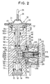
- the second expansion valve 14 is constructed as the expansion valve integrated with the electromagnetic valve and will be described more specifically with reference to FIGS. 2 to 5.
- the expansion valve 14 is constructed as a box-type expansion valve and integrally incorporates therein a low-pressure refrigerant path 140 through which the refrigerant from an outlet of the evaporator 16 and a temperature sensing mechanism (described later) for sensing a temperature of the refrigerant flowing through the low-pressure refrigerant path 140.
- a normally-closed type electromagnetic valve 20 (see FIG. 2) is integrally assembled to the box-type expansion valve 14.
- the expansion valve 14 is provided with a prism-shaped valve body 141 made of a metal such as aluminum.
- the valve body 141 is, as shown in FIG. 1, with a refrigerant inlet 141a and a refrigerant outlet 141b at a position proximate to a lower side of an outer circumferential wall thereof.
- the high-pressure side liquid-phase refrigerant from the receiver 12 flows into the refrigerant inlet 141a, whereas the low-pressure refrigerant having been decompressed and expanded in a restriction path 144 (described later) flows out through the refrigerant outlet 141b.
- the refrigerant outlet 141b is connected to a refrigerant inlet 16a of the evaporator 16.
- a low-pressure refrigerant path 140 is formed in an upstream side portion of the valve body 141 to pass through the valve body 141 in an axial direction thereof. At both end of the low-pressure refrigerant path 140, there are opened a refrigerant inlet 141c and a refrigerant outlet 141d.
- the refrigerant inlet 141c is connected to the outlet 16b of the evaporator 16 such that the gas-phase refrigerant evaporated in the evaporator 16 flows into the refrigerant inlet 141c.
- the gas-phase refrigerant further passes through the low-pressure refrigerant path 140 and flows from the refrigerant outlet 141d out of the valve body 141.
- the refrigerant outlet 141d is connected to an inlet side of the compressor 10.
- a stepped inner hole 142 having a stepped portion is coaxially formed.
- the stepped inner hole 142 passes through the low-pressure refrigerant path 140 and extends vertically (up and down direction) in the center portion of the valve body 141.
- a valve seat 143 At a lower end (one end) portion of the stepped inner hole 142, there is formed a valve seat 143, and a spherical valve element 144 is vertically movably disposed to face the valve seat 143.
- a restriction path 144a (see FIG. 2) for decompressing and expanding the high-pressure side liquid-phase refrigerant from the refrigerant inlet 141a.
- An operation rod 145 is vertically movably fitted to a lower side portion of the stepped inner hole.
- a lower end portion of the operation rod 145 contacts the spherical valve element 144 to move the spherical valve element 144.
- a small-diameter portion is formed in a lower side portion of the operation rod 145 such that an annular refrigerant path 145b is formed between the small-diameter portion 145a and the stepped inner hole 142.
- valve body 141 there are formed a communication hole 146 and a communication chamber 147 in a crossing direction at right angles from the stepped inner hole 142. In this way, the annular refrigerant path 145b always communicates with the communication chamber 147 through the communication hole 146. Further, there are provided a plurality of communication holes 146, and at an intermediate portion of the plurality of the communication holes 146, a cylindrical portion is projects in the communication chamber 147 such that a refrigerant path 148 is formed by the cylindrical portion.
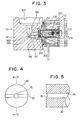
- a valve element 200 of the normally-closed type electromagnetic valve 20 is disposed to face an end face of the refrigerant path 148 such that a communication between the communication chamber 147 and the refrigerant path 148 is intermitted by the valve element 200. As shown in FIG. 3, the refrigerant path 148 communicates with the refrigerant outlet 141b.
- the electromagnetic valve 20 will described more specifically later.
- a diaphragm operating unit 30 includes an upper casing 31, a lower casing 32, and a diaphragm 33 as pressure responding member. Both of casings 31 and 32 are made of stainless type metal and fixedly holds an outer circumferential edge portion of the disc-shaped diaphragm 33 made of similar stainless type metal.
- the disc-shaped diaphragm 33 is assembled to be elastically deformable in the vertical direction of FIG. 1.
- An inner space of both of casings 31 and 32 is partitioned by the diaphragm 33 into a temperature sensing chamber (first pressure chamber) 34 and a pressure equalizing chamber (second pressure chamber) 35.
- first pressure chamber first pressure chamber
- second pressure chamber second pressure chamber
- refrigerant identical to that circulating in the refrigerant cycle is sealed under a predetermined pressure through a capillary tube 36.
- An annular opening portion 32a of the casing 32 at the lower side is fixedly screwed to a large-diameter portion 142a formed at one end portion (upper end portion) of the stepped inner hole 142 of the valve body 141.
- a rubber O-ring elastic sealing member
- the temperature sensing rod 40 is made of a metal which is superior in a thermal conductivity, such as aluminum, and is formed into a columnar shape. For sensing a temperature of the refrigerant at the outlet of the evaporator, the temperature sensing rod 40 is disposed, as shown in FIGS. 1 and 2, to pass through the low-pressure refrigerant path 140 through which the gas-phase refrigerant from the outlet of the evaporator passes.
- One end portion (upper end portion) of the temperature sensing rod 40 is constructed as a large-diameter portion 41.
- the large-diameter portion 41 is disposed in the pressure equalizing chamber 35 such that the large-diameter portion 41 may contact one side face (lower side face) of the disc-shaped diaphragm 33.
- a variation in the temperature of the temperature sensing rod 40 is transmitted to the refrigerant in the temperature sensing chamber 34 through the diaphragm 33 made of metallic thin plate.
- the refrigerant pressure in the temperature sensing chamber 34 becomes a pressure corresponding to the temperature of the refrigerant flowing the outlet of the from the outlet of the evaporator through the low-pressure refrigerant path 140.
- the temperature sensing rod 40 is axially slidably disposed in the stepped inner hole 142 of the valve body 141. A movement of the diaphragm 33 is transmitted to the valve element 144 through the operation rod 145. The other end portion (the lower end portion) of the temperature sensing rod 40 contacts one end portion (an upper end portion) of the operation rod 145.
- a rubber O-ring (elastic sealing member) 42 in a portion between the low-pressure refrigerant path 140 and the pressure equalizing chamber 35 to maintain air-tightness therebetween.
- the refrigerant pressure between the valve element 200 of the electromagnetic valve 20 and the restriction path 144a is introduced through a pressure introduction path (described below). That is, as shown in FIG. 2, a pressure chamber 43 is formed between the lower end portion of the temperature sensing rod 40 and an intermediate stepped face 142b of the stepped inner hole 142, and the pressure chamber 43 is communicated with the communication chamber 147 through the communication hole 44 provided in the valve body 141.
- a communication hole 142 is formed to pass through a center portion of the temperature sensing rod in the axial direction thereof, and as shown in FIGS. 4 and 5, a groove portion 46 having a U-shaped cross section is provided at the lower end portion of the temperature sensing rod 40. Therefore, even when the lower end portion of the temperature sensing rod 40 contacts the upper end portion of the operation rod 145, the pressure chamber 43 is always communicated with the communication hole 45 through the groove portion 46.
- the refrigerant pressure i.e., the pressure in the communication chamber 14
- the valve element 200 of the electromagnetic valve 20 and the restriction path 144a is introduced into the pressure equalizing chamber 35.
- auxiliary communication hole 45a extending radially from the center portion of the temperature sensing rod 40. Also, through the auxiliary communication hole 45a, the above-described refrigerant pressure is introduced.
- Each of the communication holes 44, 45 and 45a may have a diameter of approximately 1.0 mm, for example. Further, the groove portion having the U-shaped cross section has a depth of approximately 0.5 mm, for example.
- a rubber O-ring (elastic sealing member) 47 in a portion between the low-pressure refrigerant path 140 and the pressure chamber 43 to maintain air-tightness therebetween.
- a spring mechanism 50 for applying a predetermined spring force to the valve element 144 of the expansion valve 14 will be described.
- the accommodating chamber 51 communicates with the refrigerant inlet 141a into which the high-pressure refrigerant flows.
- a metallic support plate 52 joined by welding to the valve element 144 made of stainless.
- a coil spring 53 (spring means) contacts and supports the support plate 52.
- the other end of the coil spring 53 is supported by a metallic plug 54.
- the plug 54 functions as a cover member for closing an opening end of the accommodating chamber 51 toward the outside and is detachably fixed to the valve body 141 by screws. A fixed position of the plug by screws is adjusted so that a preset load of the coil spring 53 is adjusted. In this way, a spring force applied to the valve element 144 is adjusted.
- a superheating degree at the outlet of the evaporator, which is set by the expansion valve 14, can be adjusted by adjusting the above-described spring force.
- a rubber O-ring (elastic sealing member) 55 to maintain air-tightness between the accommodating chamber 51 and the outside.
- the normally-closed type electromagnetic valve 20 is a pilot type electromagnetic valve including a valve element 200, a electromagnet 210, and a columnar plunger 220 made of magnetic material.
- the valve member 200 has a substantially disc-shape.
- a minute valve hole 202 is formed at the center portion of the valve member 200.
- the valve hole 202 is formed in a resin member 201.
- the resin member 201 is preferably formed with resin material (e.g., fluorine type resin) which can be satisfactorily molded with high accuracy in size and can sufficiently maintain a sealing performance with an end face of the refrigerant.
- a piston member 203 made of metal such as brass. Both are connected integrally to each other by caulking or the like.
- the piston member 203 is disposed slidably in the left-right direction of FIG. 2 in an inner circumferential portion of a mounting screw member 230 made of non-magnetic metal.
- the mounting screw member 230 is for detachably fixing the normally-closed type electromagnetic valve 20 on the valve body 141.
- the mounting screw member 230 is cylindrical and made of non-magnetic metal.
- a rubber O-ring (elastic sealing member) 231 At the screw fixing portion of the mounting screw member 230, there is disposed a rubber O-ring (elastic sealing member) 231 to maintain air-tightness between the communication chamber 147 and the outside.
- the electromagnet 210 is provided with a resin bobbin winding a solenoid 211 therearound.
- a columnar magnetic pole member 213 is coaxially fitted in a hollow top end portion of the bobbin 212.
- the magnetic pole member 213 is fastened in a magnetic frame body 214 made of magnetic material by a screw 214.
- a cylindrical support member 215 made of non-magnetic material is coaxially and fixedly fitted.
- One end of the support member 215 is fixedly fitted in an inner circumferential portion of the mounting screw member 230.
- the mounting screw member 230 and the electromagnet 210 portion are integrally connected with the support member 215.
- the plunger 220 is cylindrical and made of magnetic material.
- the plunger 220 is fitted in an axial direction in a hollow portion of the support member 215.
- the plunger 220 has a valve portion 222 projecting conically from an end face at the side of the valve element 200.
- the plunger 220 is biased by the coil spring 221 in the left direction of the drawing, i.e., toward the valve element 200, such that the valve portion 222 is seated on the valve hole 202 portion of the valve element 200 to close the valve hole 202.
- a minute hole 204 for always communicating between the back pressure chamber 223 and the communication chamber 147.
- the plunger 220 when electric current is supplied to the solenoid 211 to generate a magnetic flux, the plunger 220 is attracted by the magnetic pole 213 while resisting the coil spring 221, and the valve portion 222 is separated from the valve hole 202 so that the valve hole 202 is opened. Then, the back pressure chamber 223 communicates with the refrigerant outlet 141b through the refrigerant path 148, and the pressure of the back pressure chamber 223 drops down to the pressure at the refrigerant outlet 141b (i.e., the low-pressure of the evaporator 16).
- the pressure of the communication chamber 147 is maintained at the high-pressure side pressure of the refrigeration cycle, because the communication between the communication chamber 147 and the refrigerant path 148 is interrupted so far. Therefore, the pressure of the communication chamber 147 is higher than that of the back pressure chamber 223, and the valve element 200 is moved in the right direction in FIGS. 2 and 3 by a pressure difference between both chambers 147 and 223, so that the refrigerant path 148 is opened. That is, the normally-closed type electromagnetic valve 20 moves the plunger 220 in the right direction in the drawing when electric current is supplied to the solenoid 211, to generate a pressure difference between both chambers 147 and 223. In this way, the valve element 220 is opened.
- the plunger 220 is moved in the left direction in FIGS. 2 and 3 by the spring force of the coil spring 221, and the valve portion 222 is seated on the valve hole 202 portion of the valve element 200 so that the valve hole 202 is closed. That is, the refrigerant in the communication chamber 147 is introduced through the minute hole 204 into the back pressure chamber 223 which has been maintained at the low-pressure side pressure. Therefore, the valve portion 222 of the plunger 220 is seated on the valve hole 202 to close the valve hole 202, and the valve element 200 is moved in the left direction in FIGS. 2 and 3 and is seated on the end face of the refrigerant path 148 to close the refrigerant path 148. In this way, the normally-closed type electromagnetic valve 20 is recovered to be closed.
- FIG. 1 when a driving force from the engine of the vehicle is transmitted to the compressor 10 through the electromagnetic clutch to start the compressor 10, the compressor 10 sucks and compresses the refrigerant in the path at the downstream sides of the evaporators 15 and 16, and discharges gas-phase refrigerant having a high-temperature and a high-pressure toward the condenser 11. Then, the condenser 11 cools and condenses the gas-phase refrigerant.
- the condensed refrigerant flows into the receiver 12, and the gas-phase refrigerant and the liquid-phase refrigerant are separated therein.
- the liquid-phase refrigerant flows out of the receiver 12 and flows toward the first and second expansion valves 13 and 14 disposed in parallel.
- the rear air conditioning unit 18 When there is no passenger at the rear seat side, it is not necessary to perform an air conditioning of the rear seat side, and therefore, the rear air conditioning unit 18 is not operated. Accordingly, the electric current to be supplied to the solenoid 211 of the electromagnetic valve 20 is interrupted, the valve element 200 is closed to close the refrigerant path 148. In this way, the inlet-side refrigerant path of the second evaporator 16 is closed so that the refrigerant does not circulate into the second evaporator 16.
- the liquid-phase refrigerant from the receiver 12 is decompressed and expanded in the first expansion valve 13 and becomes gas and liquid two phase refrigerant.
- the gas and liquid two phase refrigerant is evaporated while absorbing heat from conditioned air in the first evaporator 15. In this way, so that the conditioned air is cooled and blown into the front seat side in the passenger compartment to perform the air conditioning.
- the opening degree of the expansion valve 13 is automatically adjusted according to a temperature of the refrigerant at the outlet of the evaporator, sensed by the temperature sensing bulb 13a, to maintain the superheating degree of the refrigerant at the outlet of the evaporator at a predetermined value.
- the second expansion valve 14 provided in the rear air conditioning unit 18 is integrated with the electromagnetic valve 20.
- the electromagnetic valve 20 When the electromagnetic valve 20 is closed, the refrigerant does not circulate in the second evaporator 16, and therefore, the temperature of the refrigerant in the low-pressure refrigerant path 140 formed in the valve body 141 of the expansion valve 14 increases up to approximately a temperature of the passenger compartment. Accordingly, the temperature of the temperature sensing chamber 34 also corresponds to the temperature of the passenger compartment.
- the refrigerant pressure in the communication chamber 147 between the valve element 200 of the electromagnetic valve 20 and the restriction path 144a is introduced into the pressure equalizing chamber 35 through the pressure introduction path composed of the communication hole 44, the pressure chamber 43, the groove portion 46, and the communication holes 45 and 45a in this order.
- the electromagnetic valve 20 is closed, the communication chamber 147 is communicated with the high-pressure side of the refrigeration cycle through the restriction path 144a to become the high-pressure side pressure.
- the high-pressure side pressure of the refrigeration cycle is applied to the pressure equalizing chamber 35, and the high-pressure side pressure is sufficiently higher than a refrigerant saturated pressure at the temperature of the passenger compartment. Therefore, even if the temperature of the temperature sensing chamber 34 increases up to approximately the temperature of the passenger compartment, the pressure in the pressure equalizing chamber 35 is sufficiently higher than that in the temperature sensing chamber 34. As a result, the diaphragm 33 of the diaphragm operating unit 30 deforms upwardly so that the valve element 144, the operation rod 145, and the temperature sensing rod 40 are moved upwardly by the spring force of the coil spring 53. Accordingly, the valve element 144 is seated on the valve seat face 143 to be closed.
- valve element 144 and the valve seat face 143 are made of metal, the valve element 144 is not strictly closed so that the high-pressure side pressure in the accommodating chamber 51 leaks through the minute clearance between the valve element 144 and the valve seat face 143 toward the communication chamber 147.
- valve element 144 of the expansion valve 14 is closed, when electric current is supplied to the solenoid 211 of the electromagnetic valve 20 to operate the rear air conditioning unit 18, the valve element 200 of the electromagnetic valve 20 is opened so that the cylindrical refrigerant path 148 is opened.
- the valve element 144 of the expansion valve 144 is closed, a large amount of refrigerant does not start to flow suddenly after the electromagnetic valve 20 is opened.
- the opening degree of the valve element 144 of the expansion valve 14 also gradually increases with the result that the amount of the refrigerant flowing through the expansion valve 14 gradually increases. In this way, it is possible to effectively suppress the noise due to the variation in the pressure before and after the valve element 144 of the expansion valve 14 as well as the flowing noise due to the large amount of the rapid flow of the refrigerant.
- the pressure in the pressure equalizing chamber 35 of the diaphragm operating unit 30 becomes a pressure of the refrigerant at the inlet side of the evaporator 16 (the low pressure at the inlet side of the evaporator).
- the valve element 144 of the expansion valve 14 is moved to a position according to a balance of the spring force of the coil spring 53 of the spring mechanism 50 and the pressure difference between and the low pressure at the inlet side of the evaporator, which is applied to the pressure equalizing chamber 35, and the refrigerant pressure in the temperature sensing chamber 34, which corresponds to the temperature of the refrigerant at the outlet side of the evaporator.
- valve element 144 of the expansion valve 14 adjusts the opening degree of the restriction path 144a for adjusting the flow amount of the such that the refrigerant at the outlet side of the evaporator can maintain a predetermined superheating degree. That is, the expansion valve 14 adjusts the flow amount of the refrigerant as the internal equalizing type expansion valve.
- the diaphragm 33 may be made of stainless type material which is superior in the fatigue resistant characteristics, or the casings 31 and 32 may be formed in a shape having a thick wall.
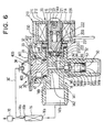
- the temperature sensing rod 40 is omitted, and instead, there is provided a temperature sensing bulb 14a corresponding to the temperature sensing bulb 13a in FIG. 1 at the refrigerant outlet portion of the evaporator 16.
- the temperature sensing bulb 14a is connected to the temperature sensing chamber 34 through the capillary tube 36'.
- a stopper member 400 for transmitting movement is interposed between the operation rod 145 and the diaphragm 33.
- the stopper member 400 has large-diameter portions 401 and 402 at both ends in the axial direction and a small-diameter portion 403 therebetween.
- a rubber O-ring (elastic sealing member) is disposed around an outer circumferential surface of the lower side large-diameter portion 402 to partition air-tightly between the pressure chamber 402 below the large-diameter portion 402 and the pressure equalizing chamber 35.
- the communication between the communication chamber 147 and the refrigerant outlet 141b is opened or closed by the valve element 200 of the electromagnetic valve 20.
- the accommodating chamber 51 for accommodating the spring mechanism 50 is formed directly at the downstream side of the refrigerant outlet 141a. Accordingly, in the second embodiment, instead of the plug 54, a support plate 54b, in which the refrigerant flow hole 54a is opened, is fixed to the valve body 141 with screws.
- a communication hole 44 for communicating the communication hole 146 formed between the valve element 144 of the expansion valve 14 and the valve element 200 of the electromagnetic valve 20 with the pressure chamber 43 below the large-diameter portion 402 of the stopper member 400.
- the high-pressure side pressure of the refrigeration cycle is applied to the pressure chamber 43 from the communication hole 146 disposed at the upstream side of the valve element 200 of the electromagnetic valve 20 through the communication hole 44.
- the stopper member 400 is pushed upwardly, and the valve element 144 of the expansion valve 14 is closed.
- the area receiving the pressure is increased as compared with the temperature sensing rod 40 in the first embodiment, so that the force for pushing the stopper member 400 upwardly can be increased.
- valve body 141 there is formed a communication hole 149 for communicating the refrigerant outlet 141b with the pressure equalizing chamber 35. More specifically, the communication hole 149 is opened at the outer circumference side of the small-diameter portion 403 located above the O-ring 47. In this way, the refrigerant pressure at the inlet side of the evaporator 16 is introduced into the pressure equalizing chamber 35 from the refrigerant outlet 141b through the communication hole 149.
- the valve element 144 of the expansion valve 14 is moved according to the refrigerant pressure in the temperature sensing chamber 34, which corresponds to the temperature of the refrigerant at the outlet side of the evaporator, detected by the temperature sensing bulb 14a, and the refrigerant pressure at the inlet side of the evaporator, which is introduced into the pressure equalizing chamber 35 through the communication hole 149.
- the opening degree (the flow amount of the refrigerant) of the restriction path 144a is adjusted.
- the pressure equalizing chamber 35 and the pressure chamber 43 are partitioned by the O-ring 47, and the high-pressure side pressure of the refrigeration cycle is not applied directly to the pressure equalizing chamber 35 when the electromagnetic valve 20 is closed. Therefore, when the diaphragm operating unit 30 is specifically designed, the diaphragm 33 or the casings 31 and 32 may have compressive strength as usual.
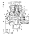
- the communication hole 149 of the valve body 141, the large-diameter portion 402 of the stopper member 400, and the O-ring 47 on the outer circumferential surface of the large-diameter portion 402 are omitted, and instead the small-diameter portion 403 of the stopper member 400 is extended up to the lower end portion. Further, a clearance portion 403a around the inner-diameter portion 403 is communicated with the communication hole 44. In this way, the pressure equalizing chamber 35 below the diaphragm 33 is communicated with the communication hole 146 and the communication chamber 147 disposed at the upstream side of the valve element 200 of the electromagnetic valve 20 through the above-described clearance 403a and the communication hole 44.
- the refrigerant pressure at the upstream side of the valve element 200 of the electromagnetic 20 is applied to the pressure equalizing chamber 35 below the diaphragm 33.
- a pressure introduction path R for applying the refrigerant pressure between the downstream side of the restriction path 144a of the expansion valve 14 and the upstream side of the valve element 200 of the electromagnetic valve 20 into the pressure equalizing chamber 35 below the diaphragm 33 in the diaphragm operating unit 30.
- the pressure introduction path R is constructed by a path composed of the communication hole 44, the pressure chamber 43, the groove portion 46, and the communication hole 45 and 45a in this order. Further, in the third embodiment, the pressure introduction path R is constructed by the communication hole 44 and the clearance portion 403a.
- the present invention is not limited to the refrigeration cycle for a vehicle, but may be widely employed in refrigeration cycle for an air conditioning apparatus, a freezing apparatus, a refrigerating apparatus, or the like, installed in a general construction building.
Landscapes
- Engineering & Computer Science (AREA)
- Physics & Mathematics (AREA)
- Mechanical Engineering (AREA)
- Thermal Sciences (AREA)
- General Engineering & Computer Science (AREA)
- Fluid Mechanics (AREA)
- Temperature-Responsive Valves (AREA)
- Air-Conditioning For Vehicles (AREA)
Claims (8)
- Mit einem Magnetventil (20) vereinigtes Expansionsventil (14), umfassend:ein Expansionsventilgehäuse (141) zur Bildung einer Außengestalt dieses Expansionsventils (14), wobei das Expansionsventilgehäuse (141) über einem Kühlmitteleinlassweg (141a, 51) zum Einführen hochdruckseitigen Kühlmittels verfügt, einen Drosselweg (144a) zum Dekomprimieren und Expandieren des aus dem Kühlmitteleinlassweg (141a, 51) eingeführten Kühlmittels und einen Kühlmittelauslassweg (145b, 146, 147, 148, 141b) zum Führen des in diesem Drosselweg (144a) dekomprimierten und expandierten Kühlmittels;ein erstes Ventilelement (144) zum Einstellen eines Öffnungsgrades dieses Drosselwegs (144a) und ein das Ventilelement betätigender Mechanismus (30) zur Bewegung des ersten Ventilelements (144); wobeidieses Magnetventil (20) integriert in diesem Expansionsventilgehäuse (141) aufgebaut ist und ein zweites Ventilelement (200) einschließt, das so angeordnet ist, dass es diesen Kühlmittetauslassweg (145b, 146, 147, 148, 141b) öffnet und schließt, undist dieses zweite Ventilelement (200) geschlossen, dieser das Ventilelement betätigende Mechanismus (30), basierend auf einem Kühlmitteldruck zwischen diesem zweiten Ventilelement (200) und diesem Drosselweg (144a) derart in Aktion tritt, dass das erste Ventilelement (144) geschlossen wird.
- Mit einem Magnetventil (20) vereinigtes Expansionsventil (14) nach Anspruch 1, wobei
dieser das Ventilelement betätigende Mechanismus (30) ein Druckansprechglied (33) zur Bewegung dieses ersten Ventilelements (144) einschließt, wobei dieses Druckansprechglied (33) den Kühlmitteldruck zwischen diesem zweiten Ventilelement (200) und diesem Drosselweg (144) aufnimmt, und
ist das zweite Ventilelement (200) geschlossen, dieses Druckansprechglied (33) durch den Kühlmitteldruck zwischen diesem zweiten Ventilelement (200) und diesem Drosselweg (144a) zum Schließen des ersten Ventilelements (144) bewegt wird. - Mit einem Magnetventil (20) vereinigtes Expansionsventil (14) nach Anspruch 2, weiter umfassend:Mittel zur Bildung einer ersten Druckkammer (34) an einer Seite dieses Druckansprechglieds (33), wobei diese erste Druckkammer (34) so ausgelegt ist, dass sie einen Druck entsprechend einer Temperatur des Kühlmittels an einem Auslass eines Verdampfers (16) aufnimmt; undMittel zur Bildung einer zweiten Druckkammer (35) an der anderen Seite dieses Druckansprechglieds (33), wobei diese zweite Druckkammer (35) den Kühlmitteldruck zwischen dem zweiten Ventilelement (200) und diesem Drosselweg (144a) aufnimmt.
- Mit einem Magnetventil (20) vereinigtes Expansionsventil (14) nach Anspruch 3, wobei dieses Expansionsventilgehäuse (41) einen Niederdruckkühlmittelweg (140) einschließt, durch welchen das Kühlmittel von diesem Auslass dieses Verdampfers (16) fließen kann.
- Mit einem Magnetventil (20) vereinigtes Expansionsventil (14) nach Anspruch 4, weiter umfassend:wobei der Kühlmitteldruck zwischen diesem zweiten Ventilelement (200) und diesem Drosselweg (144a) in diese zweite Druckkammer (35) durch diese ersten und zweiten Verbindungsmittel (43, 44, 45, 45a, 46) eingeführt wird.eine Druckfühlerstange (40), die in diesem Expansionsventilgehäuse (141) angeordnet ist und durch diesen Kühlmittelniederdruckweg (140) geht, um eine Temperatur des Kühlmittels am Auslass dieses Verdampfers (16) zu erfassen und einen Druck hiervon auf diese erste Druckkammer (34) zu übertragen;erste Verbindungsmittel (43, 44), die in diesem Expansionsventilgehäuse (141) angeordnet sind, um die Verbindung zwischen diesem zweiten Ventilelement (200) und diesem Drosselweg (144a) herzustellen; undzweite Verbindungsmittel (45, 45a, 46), die in dieser Temperaturfühlerstange (40) angeordnet sind, um diese ersten Verbindungsmittel (43, 44) mit dieser zweiten Druckkammer (35) zu verbinden;
- Mit einem Magnetventil (20) vereinigtes Expansionsventil (14) nach Anspruch 1, wobei dieser das Ventilelement betätigende Mechanismus (30) ein Druckansprechglied (33) zur Bewegung dieses ersten Ventilelements (144) einschließt,
wobei dieses mit dem Magnetventil (20) integrierte Expansionsventil (14) weiterhin umfasst:wobei ein Kühlmitteldruck an einer Abströmseite dieses zweiten Ventilelements (200) in diese zweite Druckkammer (35) eingeführt wird.Mittel zur Bildung einer ersten Druckkammer (34) an einer Seite dieses Druckansprechgliedes (33), wobei diese erste Druckkammer (34) so ausgelegt ist, dass sie einen Druck entsprechend einer Temperatur des Kühlmittels an einem Auslass eines Verdampfers (16) aufnimmt bzw. empfängt;Mittel zur Bildung einer zweiten Druckkammer (35) an der anderen Seite dieses Druckansprechelements (33);ein in dieser zweiten Druckkammer (35) angeordnetes Stopperelement (400) zur Bildung einer dritten Druckkammer (43), die von dieser zweiten Druckkammer (35) abgetrennt ist, wobei dieses Stopperelement (400) sich integral mit dem Druckansprechglied (33) bewegt, der Kühlmitteldruck zwischen diesem zweiten Ventilelement (200) und diesem Drosselweg (144a) in diese dritte Druckkammer (43) eingeführt wird; - Ein Expansionsventil gemäß Anspruch 1 verwendender Kühlzyklus, umfassend:wobei dieses Expansionsventil wenigstens eines aus einem ersten Expansionsventil (13) zum Dekomprimieren und Expandieren des in flüssiger Phase befindlichen in diesem Kondensator (11) kondensierten Kühlmittels, undeinen Kompressor (10) zum Komprimieren und Austragen von Kühlmittel;einen Kondensator (11) zum Kühlen und Kondensieren des von diesem Kompressor (10) ausgetragenen Kühlmittels;
einem zweiten Expansionsventil (14) ist, parallel zum ersten Expansionsventil (13) angeordnet, zum Dekomprimieren und Expandieren des in flüssiger Phase befindlichen in diesem Kondensator (11) kondensierten Kühlmittels, wobei der Kühlmittelzyklus weiterhin umfasst:einen ersten Verdampfer (15) zum Verdampfen des in diesem ersten Expansionsventil (13) dekomprimierten und expandierten Kühlmittels; undeinen zweiten Verdampfer (16), der parallel zum ersten Verdampfer (15) angeordnet ist, um das in diesem zweiten Expansionsventil (14) dekomprimierte und expandierte Kühlmittel zu verdampfen. - Kühlzyklus nach Anspruch 7, wobei, ist dieses zweite Ventilelement (200) geschlossen, dieser das Ventilelement betätigende Mechanismus (30) einen Kühlmitteldruck zwischen diesem zweiten Ventilelement (200) und diesem Drosselweg (144a) sowie einen Druck entsprechend einer Temperatur des Kühlmittels am Auslass dieses Verdampfers (16) aufnimmt, derart, dass dieser das Ventilelement betätigende Mechanismus (30) dieses Ventilelement (144) basierend auf diesen beiden Drücken bewegt.
Applications Claiming Priority (3)
| Application Number | Priority Date | Filing Date | Title |
|---|---|---|---|
| JP104583/97 | 1997-04-22 | ||
| JP10458397 | 1997-04-22 | ||
| JP10458397A JP3794100B2 (ja) | 1996-07-01 | 1997-04-22 | 電磁弁一体型膨張弁 |
Publications (2)
| Publication Number | Publication Date |
|---|---|
| EP0874202A1 EP0874202A1 (de) | 1998-10-28 |
| EP0874202B1 true EP0874202B1 (de) | 2003-03-05 |
Family
ID=14384468
Family Applications (1)
| Application Number | Title | Priority Date | Filing Date |
|---|---|---|---|
| EP97122936A Expired - Lifetime EP0874202B1 (de) | 1997-04-22 | 1997-12-29 | Mit einem elektromagnetischen Ventil vereinigtes Entspannungsventil und dieses verwendender Kältekreislauf |
Country Status (2)
| Country | Link |
|---|---|
| EP (1) | EP0874202B1 (de) |
| DE (1) | DE69719487T2 (de) |
Cited By (1)
| Publication number | Priority date | Publication date | Assignee | Title |
|---|---|---|---|---|
| DE10323739A1 (de) * | 2003-05-24 | 2004-12-16 | Daimlerchrysler Ag | Expansionseinheit für einen Kältemittelkreis |
Families Citing this family (4)
| Publication number | Priority date | Publication date | Assignee | Title |
|---|---|---|---|---|
| US6185959B1 (en) * | 1999-04-09 | 2001-02-13 | Eaton Corporation | Refrigerant system components with cartridge type thermal expansion valve and method of making same |
| JP4693403B2 (ja) | 2003-12-16 | 2011-06-01 | オットー・エゲルホフ・ゲーエムベーハー・ウント・コンパニ・カーゲー | 遮断弁、遮断弁を有するキット、及び膨張弁 |
| DE102004049790B4 (de) * | 2003-12-16 | 2007-05-16 | Otto Egelhof Gmbh & Co Kg | Abschaltventil, Bausatz mit einem Abschaltventil, sowie ein Expansionsventil |
| JP6323508B2 (ja) * | 2016-08-04 | 2018-05-16 | ダイキン工業株式会社 | 冷凍装置 |
Family Cites Families (5)
| Publication number | Priority date | Publication date | Assignee | Title |
|---|---|---|---|---|
| JPS6241481A (ja) * | 1985-08-16 | 1987-02-23 | Saginomiya Seisakusho Inc | 電磁弁付膨張弁 |
| JP3397862B2 (ja) * | 1993-11-30 | 2003-04-21 | 株式会社デンソー | 電磁弁付膨張弁 |
| JP3362990B2 (ja) * | 1995-02-03 | 2003-01-07 | 株式会社不二工機 | 電磁弁付膨張弁 |
| JPH0914797A (ja) * | 1995-06-27 | 1997-01-17 | Nippondenso Co Ltd | 電磁弁一体型膨張弁 |
| JP3794100B2 (ja) * | 1996-07-01 | 2006-07-05 | 株式会社デンソー | 電磁弁一体型膨張弁 |
-
1997
- 1997-12-29 DE DE69719487T patent/DE69719487T2/de not_active Expired - Lifetime
- 1997-12-29 EP EP97122936A patent/EP0874202B1/de not_active Expired - Lifetime
Cited By (2)
| Publication number | Priority date | Publication date | Assignee | Title |
|---|---|---|---|---|
| DE10323739A1 (de) * | 2003-05-24 | 2004-12-16 | Daimlerchrysler Ag | Expansionseinheit für einen Kältemittelkreis |
| DE10323739B4 (de) * | 2003-05-24 | 2008-10-30 | Daimler Ag | Expansionseinheit für einen Kältemittelkreis |
Also Published As
| Publication number | Publication date |
|---|---|
| DE69719487D1 (de) | 2003-04-10 |
| EP0874202A1 (de) | 1998-10-28 |
| DE69719487T2 (de) | 2003-09-25 |
Similar Documents
| Publication | Publication Date | Title |
|---|---|---|
| US5826438A (en) | Expansion valve integrated with electromagnetic valve and refrigeration cycle employing the same | |
| EP0924482B1 (de) | Mit einem elektromagnetischen Ventil vereinigtes Entspannungsventil | |
| US6574976B2 (en) | Refrigerant cycle system and valve device for the same | |
| US5642858A (en) | Thermal expansion valve | |
| JPH07151422A (ja) | 電磁弁付膨張弁 | |
| US7036744B2 (en) | Solenoid valve-equipped expansion valve | |
| JPH11211250A (ja) | 超臨界冷凍サイクル | |
| JP2017129173A (ja) | 流路切替弁 | |
| EP0874202A1 (de) | Mit einem elektromagnetischen Ventil vereinigtes Entspannungsventil und dieses verwendender Kältekreislauf | |
| JPH0875026A (ja) | 電磁弁 | |
| JP3362990B2 (ja) | 電磁弁付膨張弁 | |
| JP3249483B2 (ja) | 複合電磁弁及び複合電磁弁の制御方法 | |
| JP2003130500A (ja) | 電磁弁一体型膨張弁 | |
| JPH09100933A (ja) | 電磁弁 | |
| JP2009024945A (ja) | 電磁弁付膨張弁 | |
| JPH0914797A (ja) | 電磁弁一体型膨張弁 | |
| JP2018091566A (ja) | 電磁弁一体型膨張弁 | |
| JP3924935B2 (ja) | 温度式膨張弁 | |
| JPH0814711A (ja) | 電磁弁一体型レシーバおよび冷凍サイクル | |
| JP2005201484A (ja) | 冷凍サイクル | |
| JP2003156268A (ja) | 電磁膨張装置およびその制御方法 | |
| KR102446452B1 (ko) | 가변 용량 압축기용 제어 밸브 | |
| JPH10170105A (ja) | 膨張弁 | |
| JPH08240278A (ja) | 冷凍サイクル装置 | |
| JPH0814706A (ja) | 電磁弁付膨脹弁 |
Legal Events
| Date | Code | Title | Description |
|---|---|---|---|
| PUAI | Public reference made under article 153(3) epc to a published international application that has entered the european phase |
Free format text: ORIGINAL CODE: 0009012 |
|
| AK | Designated contracting states |
Kind code of ref document: A1 Designated state(s): DE FR GB |
|
| AX | Request for extension of the european patent |
Free format text: AL;LT;LV;MK;RO;SI |
|
| 17P | Request for examination filed |
Effective date: 19981211 |
|
| AKX | Designation fees paid |
Free format text: DE FR GB |
|
| 17Q | First examination report despatched |
Effective date: 20010404 |
|
| GRAH | Despatch of communication of intention to grant a patent |
Free format text: ORIGINAL CODE: EPIDOS IGRA |
|
| GRAH | Despatch of communication of intention to grant a patent |
Free format text: ORIGINAL CODE: EPIDOS IGRA |
|
| GRAA | (expected) grant |
Free format text: ORIGINAL CODE: 0009210 |
|
| AK | Designated contracting states |
Designated state(s): DE FR GB |
|
| REG | Reference to a national code |
Ref country code: GB Ref legal event code: FG4D |
|
| REF | Corresponds to: |
Ref document number: 69719487 Country of ref document: DE Date of ref document: 20030410 Kind code of ref document: P |
|
| ET | Fr: translation filed | ||
| PLBE | No opposition filed within time limit |
Free format text: ORIGINAL CODE: 0009261 |
|
| STAA | Information on the status of an ep patent application or granted ep patent |
Free format text: STATUS: NO OPPOSITION FILED WITHIN TIME LIMIT |
|
| 26N | No opposition filed |
Effective date: 20031208 |
|
| REG | Reference to a national code |
Ref country code: GB Ref legal event code: 746 Effective date: 20040406 |
|
| PGFP | Annual fee paid to national office [announced via postgrant information from national office to epo] |
Ref country code: DE Payment date: 20141211 Year of fee payment: 18 Ref country code: GB Payment date: 20141219 Year of fee payment: 18 |
|
| PGFP | Annual fee paid to national office [announced via postgrant information from national office to epo] |
Ref country code: FR Payment date: 20141219 Year of fee payment: 18 |
|
| REG | Reference to a national code |
Ref country code: DE Ref legal event code: R119 Ref document number: 69719487 Country of ref document: DE |
|
| GBPC | Gb: european patent ceased through non-payment of renewal fee |
Effective date: 20151229 |
|
| REG | Reference to a national code |
Ref country code: FR Ref legal event code: ST Effective date: 20160831 |
|
| PG25 | Lapsed in a contracting state [announced via postgrant information from national office to epo] |
Ref country code: GB Free format text: LAPSE BECAUSE OF NON-PAYMENT OF DUE FEES Effective date: 20151229 Ref country code: DE Free format text: LAPSE BECAUSE OF NON-PAYMENT OF DUE FEES Effective date: 20160701 |
|
| PG25 | Lapsed in a contracting state [announced via postgrant information from national office to epo] |
Ref country code: FR Free format text: LAPSE BECAUSE OF NON-PAYMENT OF DUE FEES Effective date: 20151231 |