EP0874411A1 - Plaque d'electrode pour un accumulateur au plomb et procede de fabrication - Google Patents
Plaque d'electrode pour un accumulateur au plomb et procede de fabrication Download PDFInfo
- Publication number
- EP0874411A1 EP0874411A1 EP96927499A EP96927499A EP0874411A1 EP 0874411 A1 EP0874411 A1 EP 0874411A1 EP 96927499 A EP96927499 A EP 96927499A EP 96927499 A EP96927499 A EP 96927499A EP 0874411 A1 EP0874411 A1 EP 0874411A1
- Authority
- EP
- European Patent Office
- Prior art keywords
- lead
- fibre
- cadmium
- lead alloy
- electrode plate
- Prior art date
- Legal status (The legal status is an assumption and is not a legal conclusion. Google has not performed a legal analysis and makes no representation as to the accuracy of the status listed.)
- Withdrawn
Links
- 239000002253 acid Substances 0.000 title claims abstract description 27
- 238000000034 method Methods 0.000 title claims description 43
- 239000000835 fiber Substances 0.000 claims abstract description 231
- 229910000978 Pb alloy Inorganic materials 0.000 claims abstract description 136
- BDOSMKKIYDKNTQ-UHFFFAOYSA-N cadmium atom Chemical compound [Cd] BDOSMKKIYDKNTQ-UHFFFAOYSA-N 0.000 claims abstract description 74
- 229910052793 cadmium Inorganic materials 0.000 claims abstract description 73
- 239000000203 mixture Substances 0.000 claims abstract description 32
- 238000004519 manufacturing process Methods 0.000 claims abstract description 4
- 238000003756 stirring Methods 0.000 claims abstract description 4
- 229910045601 alloy Inorganic materials 0.000 claims abstract description 3
- 239000000956 alloy Substances 0.000 claims abstract description 3
- 238000003825 pressing Methods 0.000 claims description 32
- 238000002844 melting Methods 0.000 claims description 30
- 230000008018 melting Effects 0.000 claims description 30
- OKTJSMMVPCPJKN-UHFFFAOYSA-N Carbon Chemical compound [C] OKTJSMMVPCPJKN-UHFFFAOYSA-N 0.000 claims description 23
- 230000005611 electricity Effects 0.000 claims description 23
- 229910052709 silver Inorganic materials 0.000 claims description 16
- 239000004332 silver Substances 0.000 claims description 16
- OYPRJOBELJOOCE-UHFFFAOYSA-N Calcium Chemical compound [Ca] OYPRJOBELJOOCE-UHFFFAOYSA-N 0.000 claims description 14
- PEDCQBHIVMGVHV-UHFFFAOYSA-N Glycerine Chemical compound OCC(O)CO PEDCQBHIVMGVHV-UHFFFAOYSA-N 0.000 claims description 14
- 229910052791 calcium Inorganic materials 0.000 claims description 14
- 239000011575 calcium Substances 0.000 claims description 14
- 229910052799 carbon Inorganic materials 0.000 claims description 13
- RYGMFSIKBFXOCR-UHFFFAOYSA-N Copper Chemical group [Cu] RYGMFSIKBFXOCR-UHFFFAOYSA-N 0.000 claims description 9
- 229910052802 copper Inorganic materials 0.000 claims description 9
- 239000010949 copper Substances 0.000 claims description 9
- 239000000126 substance Substances 0.000 claims description 9
- 229910052787 antimony Inorganic materials 0.000 claims description 8
- WATWJIUSRGPENY-UHFFFAOYSA-N antimony atom Chemical compound [Sb] WATWJIUSRGPENY-UHFFFAOYSA-N 0.000 claims description 8
- 229920002972 Acrylic fiber Polymers 0.000 claims description 7
- 235000011187 glycerol Nutrition 0.000 claims description 7
- 238000010892 electric spark Methods 0.000 claims description 6
- 239000011148 porous material Substances 0.000 claims description 5
- 235000019353 potassium silicate Nutrition 0.000 claims description 5
- NTHWMYGWWRZVTN-UHFFFAOYSA-N sodium silicate Chemical compound [Na+].[Na+].[O-][Si]([O-])=O NTHWMYGWWRZVTN-UHFFFAOYSA-N 0.000 claims description 5
- 238000007664 blowing Methods 0.000 claims description 3
- 238000005520 cutting process Methods 0.000 claims description 3
- 239000000758 substrate Substances 0.000 abstract 3
- 229910006654 β-PbO2 Inorganic materials 0.000 description 15
- 239000013078 crystal Substances 0.000 description 12
- 238000002156 mixing Methods 0.000 description 10
- BQCADISMDOOEFD-UHFFFAOYSA-N Silver Chemical compound [Ag] BQCADISMDOOEFD-UHFFFAOYSA-N 0.000 description 9
- 239000000463 material Substances 0.000 description 9
- 239000010410 layer Substances 0.000 description 7
- 238000006243 chemical reaction Methods 0.000 description 6
- 239000003792 electrolyte Substances 0.000 description 6
- 239000002344 surface layer Substances 0.000 description 6
- 230000000694 effects Effects 0.000 description 5
- WABPQHHGFIMREM-UHFFFAOYSA-N lead(0) Chemical compound [Pb] WABPQHHGFIMREM-UHFFFAOYSA-N 0.000 description 5
- 238000002360 preparation method Methods 0.000 description 5
- QVGXLLKOCUKJST-UHFFFAOYSA-N atomic oxygen Chemical compound [O] QVGXLLKOCUKJST-UHFFFAOYSA-N 0.000 description 4
- 238000007600 charging Methods 0.000 description 4
- 238000005516 engineering process Methods 0.000 description 4
- 239000001301 oxygen Substances 0.000 description 4
- 229910052760 oxygen Inorganic materials 0.000 description 4
- 238000006555 catalytic reaction Methods 0.000 description 3
- 230000007797 corrosion Effects 0.000 description 3
- 238000005260 corrosion Methods 0.000 description 3
- 230000002708 enhancing effect Effects 0.000 description 3
- 238000000605 extraction Methods 0.000 description 3
- 239000004744 fabric Substances 0.000 description 3
- 238000007789 sealing Methods 0.000 description 3
- KEQXNNJHMWSZHK-UHFFFAOYSA-L 1,3,2,4$l^{2}-dioxathiaplumbetane 2,2-dioxide Chemical compound [Pb+2].[O-]S([O-])(=O)=O KEQXNNJHMWSZHK-UHFFFAOYSA-L 0.000 description 2
- UFHFLCQGNIYNRP-UHFFFAOYSA-N Hydrogen Chemical compound [H][H] UFHFLCQGNIYNRP-UHFFFAOYSA-N 0.000 description 2
- 240000008415 Lactuca sativa Species 0.000 description 2
- 238000007599 discharging Methods 0.000 description 2
- 239000001257 hydrogen Substances 0.000 description 2
- 229910052739 hydrogen Inorganic materials 0.000 description 2
- 239000007788 liquid Substances 0.000 description 2
- 239000002184 metal Substances 0.000 description 2
- 229910052751 metal Inorganic materials 0.000 description 2
- 239000000843 powder Substances 0.000 description 2
- 235000012045 salad Nutrition 0.000 description 2
- 238000003860 storage Methods 0.000 description 2
- 229910000925 Cd alloy Inorganic materials 0.000 description 1
- 230000015572 biosynthetic process Effects 0.000 description 1
- 150000001721 carbon Chemical class 0.000 description 1
- 239000003610 charcoal Substances 0.000 description 1
- 239000011248 coating agent Substances 0.000 description 1
- 238000000576 coating method Methods 0.000 description 1
- 230000008602 contraction Effects 0.000 description 1
- 238000002788 crimping Methods 0.000 description 1
- 238000003487 electrochemical reaction Methods 0.000 description 1
- 238000001914 filtration Methods 0.000 description 1
- 239000011888 foil Substances 0.000 description 1
- 239000007789 gas Substances 0.000 description 1
- 238000010438 heat treatment Methods 0.000 description 1
- 230000010355 oscillation Effects 0.000 description 1
- 238000005192 partition Methods 0.000 description 1
- 238000007747 plating Methods 0.000 description 1
- 230000010287 polarization Effects 0.000 description 1
- 238000010278 pulse charging Methods 0.000 description 1
- 238000004064 recycling Methods 0.000 description 1
- 239000011232 storage material Substances 0.000 description 1
- 230000002459 sustained effect Effects 0.000 description 1
- XLYOFNOQVPJJNP-UHFFFAOYSA-N water Substances O XLYOFNOQVPJJNP-UHFFFAOYSA-N 0.000 description 1
- 229910006531 α-PbO2 Inorganic materials 0.000 description 1
Images


Classifications
-
- H—ELECTRICITY
- H01—ELECTRIC ELEMENTS
- H01M—PROCESSES OR MEANS, e.g. BATTERIES, FOR THE DIRECT CONVERSION OF CHEMICAL ENERGY INTO ELECTRICAL ENERGY
- H01M6/00—Primary cells; Manufacture thereof
- H01M6/42—Grouping of primary cells into batteries
- H01M6/46—Grouping of primary cells into batteries of flat cells
- H01M6/48—Grouping of primary cells into batteries of flat cells with bipolar electrodes
- H01M6/485—Side-by-side bipolar batteries
-
- H—ELECTRICITY
- H01—ELECTRIC ELEMENTS
- H01M—PROCESSES OR MEANS, e.g. BATTERIES, FOR THE DIRECT CONVERSION OF CHEMICAL ENERGY INTO ELECTRICAL ENERGY
- H01M4/00—Electrodes
- H01M4/02—Electrodes composed of, or comprising, active material
- H01M4/14—Electrodes for lead-acid accumulators
-
- H—ELECTRICITY
- H01—ELECTRIC ELEMENTS
- H01M—PROCESSES OR MEANS, e.g. BATTERIES, FOR THE DIRECT CONVERSION OF CHEMICAL ENERGY INTO ELECTRICAL ENERGY
- H01M4/00—Electrodes
- H01M4/02—Electrodes composed of, or comprising, active material
- H01M4/64—Carriers or collectors
- H01M4/70—Carriers or collectors characterised by shape or form
- H01M4/72—Grids
- H01M4/73—Grids for lead-acid accumulators, e.g. frame plates
-
- H—ELECTRICITY
- H01—ELECTRIC ELEMENTS
- H01M—PROCESSES OR MEANS, e.g. BATTERIES, FOR THE DIRECT CONVERSION OF CHEMICAL ENERGY INTO ELECTRICAL ENERGY
- H01M6/00—Primary cells; Manufacture thereof
- H01M6/42—Grouping of primary cells into batteries
- H01M6/46—Grouping of primary cells into batteries of flat cells
- H01M6/48—Grouping of primary cells into batteries of flat cells with bipolar electrodes
-
- Y—GENERAL TAGGING OF NEW TECHNOLOGICAL DEVELOPMENTS; GENERAL TAGGING OF CROSS-SECTIONAL TECHNOLOGIES SPANNING OVER SEVERAL SECTIONS OF THE IPC; TECHNICAL SUBJECTS COVERED BY FORMER USPC CROSS-REFERENCE ART COLLECTIONS [XRACs] AND DIGESTS
- Y02—TECHNOLOGIES OR APPLICATIONS FOR MITIGATION OR ADAPTATION AGAINST CLIMATE CHANGE
- Y02E—REDUCTION OF GREENHOUSE GAS [GHG] EMISSIONS, RELATED TO ENERGY GENERATION, TRANSMISSION OR DISTRIBUTION
- Y02E60/00—Enabling technologies; Technologies with a potential or indirect contribution to GHG emissions mitigation
- Y02E60/10—Energy storage using batteries
Definitions
- the invention relates to an electrode plate for a lead acid accumulator and its producing method.
- an electrode plate which consists of two overlain electrically conducting plates with the same structure.
- the peripheries of the adjacent faces of two electrically conducting plates are provided with a main rib and each of electrically conducting plates is provided with substantially equal quantity of liquid incoming apertures.
- the adjacent faces of two electrically conducting plates are coated with lead powder.
- the binding strength of the lead powder coating to the electrode plate is enhanced by providing crimping edge around peripheries of the adjacent faces, or arranging reinforce ribs on the adjacent faces of electrically conducting plates.
- This patent has raised the lifetime of the electrode plate at certain level. However, from the point of view of overall behavior of the accumulator, the over thickness of the electrode plate leads to the reduction of specific energy.
- Another Chinese patent application CN 2073171U entitled “lead acid accumulator having high specific energy and long lifetime", issued on March 13, 1991, proposes a technical solution to reduce the thickness of an electrode plate in an accumulator, the way of which is to thin the plate grid of positive electrode plate to 4.0-7.5 mm.
- the plate grid of a negative electrode plate is also to be thinned correspondingly, so that in a same container of the lead acid accumulator the number of electrode plates is increased relatively (i.e. the surface area is increased), and the polarization current for charging and discharging is reduced. Therefore, the specific energy is increased under the precondition that the lifetime is not damaged.
- the object of the present invention is to provide an electrode plate having high specific energy, high power, long lifetime, resistance to overdischarge and rapid charging, as well as its producing method.
- the invention provides an electrode plate for lead acid accumulator comprising:
- the invention also provides a method for producing the electrode plate, comprising following steps:
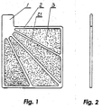
- the electrode plate for a lead acid accumulator comprises activated bases 3, 301, 302, and plate grids 2, 7 for collecting electrical current and conducting electricity, as well as plates 4, 5 for enhancing the mechanical strength of the activated base. It is understood that the plate grids 2, 7 also have the function for enhancing the mechanical strength of the activated base.
- the activated base according to the present invention is formed by mixing lead fibre and lead alloy fibre.
- the term "fibre” mentioned in the present invention means a very thin wire.
- the term “fibre” mention in the present invention and the term “ one or more fibre sections” below have the same meaning sometimes.
- fibre felt or fibre cloth can be produced in the manner similar to the method of nonwoven cloth papermaking (AGM manner) with a lot of pores among fibres.
- AGM manner the method of nonwoven cloth papermaking
- the mixing ratio among various fibres must be kept homogeneous, i.e. the ratio of various fibres per equal unit area must be similar.
- the activated base is produced from bunched fibres, the fibre bunches can be made from the same fibres, or from various fibres under given mixing ratio. Generally speaking, if the number of fibres is quite great, it is better to bunch various fibres under given mixing ratio at first, and then the bunches of fibres are mixed to produce the activated base.
- the activated base produced according to the above mentioned method possesses the structure similar to felt or cloth.
- the base block which is produced according to the above mentioned method can be arranged alternately with lead alloy felt which is fully made from lead alloy fibre. Then they are combined together by pressing, forming an activated base with better strength and current collecting and electricity conducting properties.
- the mixed fibre used in the present invention consists mainly of lead fibre and lead alloy fibre in a given weight ratio.
- some other fibres and impregnants can be also added thereinto.
- the electrode plate for a lead acid accumulator according to the present invention can be also produced from lead fibre and lead alloy fibre.
- lead fibre accounts for 60 - 90 wt% of total weight of lead fibre and lead alloy fibre. Meanwhile, the surfaces of all lead fibre are plated with cadmium which accounts for 1-5 wt%.
- an activated base according to the present invention is used in a positive electrode plate, on the surface of lead fibre grows a layer of ⁇ -PbO 2 crystal lattice.
- the surface of lead fibre remains unchanged.
- the lead fibre of the electrode plate can form ⁇ -PbO 2 crystal lattice on the positive electrode plate under the catalysis of cadmium plated on the surface; meanwhile the ⁇ -PbO 2 crystal lattice develops from surface to deeper portions, and finally a state where the core is pure lead and the surface layer is of ⁇ -PbO 2 crystal lattice is formed.
- ⁇ -PbO 2 crystal lattice on the surface layer of the electrode plate reacts with acid to form electric charge and the pure lead core is used as a channel for transmitting electricity.
- the lead alloy fibre accounts for 10-40 wt% of the total weight of lead fibre and lead alloy fibre. Meanwhile the surface thereof can be plated with cadmium which accounts for 1-5 wt%.
- ⁇ -PbO 2 crystal lattice is formed on the surface layer of lead alloy fibre in the positive electrode plate, while a pure lead layer is formed on the surface of lead alloy fibre in the negative electrode plate.
- the initial alloy state always remains in the core of the lead alloy fibre.
- the key point of the present invention is to mix the above mentioned two fibres under given ratio for producing an activated base to be used in the electrode plate for a lead acid accumulator.
- Lead ally fibre itself possesses high strength, satisfactory corrosion resistance and rather good electric conductivity. Therefore, in combination with the plate grid for collecting current and conducting electricity, the base which consists of mixture of lead fibre and lead alloy fibre can meet the demands on the strength and the current collecting and electricity conducting properties during utilization, and can prevent the electrode plate from a poor mechanical strength and the short circuit in the interior of the accumulator.
- lead fibre plays the main role in producing electric charge, and lead alloy fibre in collecting current and conducting electricity as well as in supporting the whole electrode plate. Furthermore, since the lead alloy fibre contains a small amount of cadmium, ⁇ -PbO 2 crystal lattice can always be maintained on the surface of the positive electrode plate formed by these two fibres so as to keep the plate in a full electricity storage state.
- ⁇ -PbO 2 Since the microsurface area of ⁇ -PbO 2 is about 20 times larger than that of ⁇ -PbO 2 crystal lattice, the ability in storing electricity of the former is much greater than that of the latter.
- ⁇ -PbO 2 is resulted directly from the reaction on the surface layers of the lead fibre and the lead alloy fibre, and therefore ⁇ -PbO 2 can attach firmly on the fibre and is not prone to fall off.
- the oscillation caused by large current and pulse charging can be sustained.
- lead sulphate since ⁇ -PbO 2 and lead sulphate do not belong to the same crystal, lead sulphate does not nucleate on the surfaces of these fibres.
- ⁇ -PbO 2 can also be formed and is involved in the reaction, and therefore large current output can be kept for a long time in the discharging process.
- the nodes among various fibres in the mixed fibres are slightly melted together using electric spark discharge technology, so that in the core of whole electrode plate forms a reliable network for current collection and electricity conduction and that the connection strength among various fibres in the whole electrode plate is further enhanced.
- oxide in order to use electric spark discharge technology, on the surface of lead fibre and lead alloy fibre, oxide must exist. Therefore the second role of cadmium plating is used to substitute the oxide layer so that the electric spark discharge technology can be realized.
- the respective weight percentages of compositions preferably are: 88-98.5 wt% for lead, 1-7 wt% for antimony and 0.5-5 wt% for cadmium.
- the lead alloy fibre prepared according to the above mentioned prescription is mainly used in a conventional accumulator and has rather low cost.
- the respective weight percentages of compositions can be for example : 94-99.32 wt% for lead, 0.5-5 wt% for cadmium, 0.08-0.5 wt% for calcium and 0.1-0.5 wt% for silver.
- the lead alloy fibre produced according to this prescription possesses rather good corrosion resistance and can raise the lifetime of an accumulator.
- the cost for producing such kind of lead alloy fibre is rather high, and the loss of electrolyte is quite large, since the over potential of hydrogen and oxygen is reduced due to the addition of silver.
- the activated base according to the present invention can further contain other tiny fibres.
- These tiny fibres comprise carbon fibre and other organic chemical fibres.
- the main object to add carbon fibre is to make up for insufficient current collecting and electricity conducting properties of lead alloy fibre. Especially when the weight percentage of lead alloy fiber is quite low and the current collecting and electricity conducting effect is unsatisfactory, the addition of carbon fibre is given amount does not increase the weight obviously, but can obtain good current collecting and electricity conducting effect.
- the added amount of carbon fibre accounts for 0.1-0.5 wt% of total weight of lead fibre and lead alloy fibre.
- other organic chemical fibres also can be added into, mainly such as acrylic fibres which posses acid corrosion resistance and good tensile strength.
- the addition of these fibres is mainly for enhancing the strength of whole electrode plate.
- the added organic chemical fibres can play a role similar to bundle effect of string or network to integrate various fibres firmly.
- the added amount of organic chemical fibres should account for 0.1-0.5 wt% of total weight of lead fibre and lead alloy fibre.
- the base after preparation of the activated base according to the present invention, can be put into an impregnant.
- the preferred impregnant is polytetrafluoroethlene.
- the soakage of whole activated base can prevent the fibres from movement relative to each other to avoid the reduction of strength of the activated base.
- the added amount of the impregnant accounts for 0.1-0.5wt% of the weight of the base.
- 0.1-0.5 wt% carbon powder can also be added, such as acetylene carbon, expandable graphite powder, charcoal powder or activated carbon powder. All the above mentioned carbon fibres, organic chemical fibres and carbon powders are added at the time of mixing various fibres before the activated base is formed, but the impregnant is added after the activated base is formed.
- the plate grid 2 which plays a role of current collection and electricity conduction and enhances the mechanical strength of the activated base, is integratively fixed onto the activated base 3.
- it is preferably to form the plate grid 2 directly on the activated base 3 by means of melting pressing the activated base 3. Since the plate grid 2 obtained by melting pressing consists of same material as the activated base, the electrical connection between the plate grid 2 and the activated base 3 is good land the interior resistance is less than that in a conventional electrode plate.
- non-activated material is reduced, i.e. the weight percentage of activated material is increased.
- the plate grid 2 comprises grid strips 21, which are preferably radialized and converge to the connection point of the plate grid 2 with a lug to be mentioned below, making contribution to current collection and electricity conduction.
- the plate grid 2 can be also made of lead alloy fibre in the form of a porous net (not shown ) having larger pores, then is soaked with common lead paste to help the electrode plate with the overall properties better than that of the conventional pasted electrode plate.
- a lug 1 is connected as a joint among the electrode plates.
- the lug 1 can be pressed out simultaneously with the formation of the plate grid 2 when the latter is being produced by melting pressing.
- an additional lug 1 is provided after the activated base 3 and the plate grid 2 have been integrated, i.e. the lug is a separate member such as a lead block (Figs. 5 and 6 ), which has a groove with a width corresponding to the thickness of the activated base 3 and can be fixed on the formed plate grid 2 by melting pressing.
- compositions of the above mentioned lead alloy fibre felt can be the same as that of the lead alloy fibre in the activated base 3.
- the main role of the lead alloy fibre felt is to enhance the strength and the current collection an electricity conduction properties of the electrode plate, the diameter of its lead alloy fibre should be greater, for example, bunches of lead alloy fibre can be used.
- FIG. 3 and 4 An alternative embodiment of arrangement for assuring the mechanical strength of the base according to the present invention is shown in Figs. 3 and 4.
- the arrangement consist of a bimetallic plate made of lead and another metal with satisfactory electric conductivity.
- the bimetallic plate is used both for substituting the elements connected in series between single accumulator cells, as well as for forming a bipolar electrode plate.
- the interior resistance of the electrode plate formed in such a manner is low.
- the activate bases 301, 302 which are attached on both sides of the bimetallic plate are of circular shape, on the side faces of which bases grids 7 are formed in order to assure the activated bases 301, 302 to have better strength.
- the plate grid 7 comprises radial pressed dints integrally formed on the bases 301, 302.
- the inner end 91 of the notch 9 is a semicircle and is coaxial with the respective circular activated bases.
- the width of the notch is equal to the diameter of the semicircle.
- the bimetallic plate structure consists of a metallic plate 4 on which surface a thin lead layer is plated and a lead plate 5 closely fixed thereon.
- a semicircular through hole 8 In the central part of the bimetallic plate, there is a semicircular through hole 8, which shape corresponds to the semicircular interior end 91 of the elongated notch 9 of the activated bases 301, 302.
- the metallic plate should be made of metal having definite strength and satisfactory electric conductivity. In general, it is better of pure copper. Both the surfaces of the metallic and the lead plates should be rough, i. e. they are full of small projection and cavities in order to make the connection of the copper plate 4 and the lead plate 5 with both activated bases 301, 302 firm.
- the method adopted in be present invention is to provide thorns 6 on both surfaces of be copper plate 4 and one surface of the plate 5 by bumping.
- the copper plate 4 is connected with one surface of lead plate 5 without the thorns 6 to form the bimetallic plate structure.
- the height of the thorns 6 on one face of the copper plate 4 for connection with be lead plate 5 must be slightly greater than the thickness of the lead plate 5, and the height of its thorns 6 on the other face for connection with be activated base 302 must be slightly greater than the thickness of the activated base 302.
- it is required that the height of the thorns 6 on the lead plate 5 must be greater than the thickness of the activated base 301 in order to assure a firmly attachement.
- the lead plate 5 of the bimetallic plate shall functions as a positive electrode , when it is arranged in the accumulator, in order to prevent copper of the copper plate 4 from entering into electrolyte so as to affect the properties of be accumulator.
- the crimped edges 41, 51 are provided for accommodating sealing gaskets, also for protecting sealing gaskets in practice.
- the semicircular through hole 8 of the bimetallic plate must be fully filled with pure lead to form connecting point of the electrode plates, i.e. the lug. Meanwhile, the thickness of the lug must be greater than that of the whole electrode plate.
- the positive electrode i. e. the side where be lead plate of the bimetallic plate is located
- the oxygen which is created on the positive electrode can flow upward and combines with hydrogen on the negative electrode to form water, so that the oxygen circulation can be realized under the fully sealing condition.
- Figs. 1 and 2 show the example 1 according to the present invention.
- the lead fibre and the lead alloy fibre are produced by melting pressing, cutting or melting blowing etc.
- the diameters of the produced fibres are for example 8 micrometer and 15 micrometer respectively.
- cadmium is plated correspondingly, which accounts for 2 wt% of respective weights of lead fibre and lead alloy fibre.
- compositions of the used lead alloy fibre are of 2 wt% antinomy, 2 wt% cadmium and 96 wt% lead.
- each lead fibre section is 1 mm and the length of each lead alloy fibre section is 2.5 mm.
- the sections of the lead fibre and the lead alloy fibre are mixed according to the weight ratio of 9 : 1. Then the mixture is put into a first container filled with glycerine and is stirred well. Then the contents in the first container are poured into the second container with a lot of pores on the bottom, and the glycerine is extracted by means of a vacuum pump which is connected to the lower part of the second container and applies extraction from bottom. Moreover, a rubber piston is located immediately on the mixture in the second container and has a diameter matched with that of the container to apply pressure from top. Therefore, a blank block with homogeneous porosity can be produced by the operation of the vacuum pump and the piston. After the blank block is pressed, filtrated and extracted, most of glycerine can be extracted. Then the blank block is] cleaned and dried.
- glycerine at the same time it also involves water glass and salad oil mentioned in the following examples
- the fibre sections therein can flow three-dimensionally during stirring to attain homogeneous mixing effect among various fibre sections and interweaving effect with each other.
- a lead block 101 which has a groove 10 with a width corresponding to the thickness of the blank block is arranged thereon by means of melting pressing, and an electrode plate for lead acid accumulator is produced.
- the plate grid 2 is a frame having arms extending radially or in other direction and making of lead fibre and lead alloy fibre.
- the configuration of the frame is a square.
- the activated base 3 is a woolen felt- like porous plate consisting of lead fibre and lead alloy fibre interwoven with each other. The material of the activated base 3 appears in the space between the arms of the frame of the plate grid.
- the lug 1 is a lead block having a groove 10 with the width corresponding to the thickness of the plate grid 2, and the lug can be fixed on the plate grid through the groove.
- Lead fibre sections with diameter of 80 micrometer and length of 25 mm and lead alloy fibre sections with diameter of 250 micrometer and length of 25 mm are produced according to the method mentioned in example 1.
- the lead alloy fibre consists of 0.5 wt% cadmium, 1 wt% antimony and 98.5 wt% lead.
- cadmium which accounts for 5 wt% of their respective weights is plated respectively.
- the above mentioned lead and lead alloy fibres are mixed according to the weight ratio of 6 : 4. Then the mixture is poured into the first container filled with water glass solution.
- acrylic fibres accounting for 0.1 wt% of total weight of above two fibres, carbon fibres accounting for 0.1 wt% and carbon powder accounting for 0.1 wt% are added and stirred homogeneously.
- a lead alloy fibre felt used with the blank block is produced from lead alloy fibre with diameter of 250 micrometer and length of 25 mm according to the above mentioned method.
- the lead alloy consists of 7 wt% antinomy, 5 wt% cadmium and 88 wt% lead.
- One lead alloy fibre felt is then sandwiched between above mentioned two blank blocks. Afterward the sandwich is integrated by heating and pressing. Meanwhile a plate grid with a latticed shape is formed by melting pressing. Finally, after a lug is fixed by melting pressing, an electrode plate according to the present invention is thus produced.
- the structure of the electrode plate in the present example is basically similar to that in example 1, and the only difference lies in that the plate grid 2 is a square frame with a latticed shape formed on the sandwich which is obtained after pressing two activated bases with one porous matter sandwiched therebetween wherein the latter is interwoven by lead alloy fibres. Meanwhile, the plate grid 2 and the activated base 3 contain 0.1 wt% acrylic fibres, 0.1 wt% carbon fibres and 0.1 wt% carbon powder.
- two circular bases 301 and 302 are produced according to the method described in example 1.
- An elongated notch 9 is formed and extends from the said edge to the centre of the blank block.
- the inner end 91 of the elongated notch 9 of the base is a semicircle which is coaxial with the circular base.
- pressing dints 7 can be formed by melting pressing. However the temperature of melting pressing has to be lower than the melting point of lead.
- the circular bases 301, 302 consist of lead fibre which has diameter of 2 micrometer and length of 1 mm and which surface is plated with 2 wt% cadmium and lead alloy fibre which has diameter of 5 micrometer and length of 2.0 mm and which surface is plated with 2 wt% cadmium.
- the mixing weight ratio between lead fibre and lead alloy fibre is 9 : 1.
- the solution to be used is glycerine.
- One plate of the bimetallic plate structure is a copper plate 4 with thickness of 0.5 mm. Both faces of this plate 4 are bumped with thorns 6 and are plated with lead having thickness of 0.2 mm. Then it is fixedly connected to a lead plate 5 which has thickness of 0.5 mm. One of the surface of plate 5 is also bumped with thorns 6. In the centre of the plate struature, there is a through hole 8 which shape corresponds to the semicircular inner end 91 of the elongated notch 9 in the circular blank blocks 301, 302.
- a circular base is pricked by thorns 6 respectively.
- the elongated notches 9 of both bases 301, 302 are arranged in same direction. Then the semicircular through hole 8 on the metallic plate and the semicircular inner ends 91 are filled with pure lead which height should be slightly greater than the thickness of whole electrode plate. Thus an electrode plate for a lead acid accumulator is produced.
- Lead fibre sections with diameter of 60 micrometer and length of 20 mm and lead alloy fibre sections with diameter of 200 micrometer and length of 25 mm are produced according to the method mentioned in example 1.
- the lead alloy fibre consists of 5 wt% cadmium, 7 wt% antimony and 88 wt% lead.
- cadmium which accounts for 4 wt% of their respective weights is plated respectively.
- the above mentioned lead and lead alloy fibres are mixed according to the weight ratio of 7 : 3. Then the mixture is poured into salad oil and stirred homogeneously, afterward is poured into a container with a porous bottom. After pressing, filtering and extraction, the blank block is cleaned and dried to have a required form. As an alternative method, gravity-forced extraction may be used so as to clean and dried the blank block.
- the lead alloy fibre felt is produced according to the method in example 2.
- the lead alloy fibre making from the felt has diameter of 220 micrometer and includes 5 wt% antinomy, 3 wt% cadmium and 92 wt% lead.
- the structure of the electrode plate produced according to the above mentioned method has a plate grid 2 which is a frame having a lattice shape and make of lead alloy.
- the activated base 3 is produced from three layers of porous matter of lead alloy fibre and two layers of porous matter of mixed fibre by pressing. Thus an electrode plate with a stratified structure is prepared.
- the lug 1 is still a lead block having corresponding groove which is used for fixing the lug on the plate grid 2.
- the blank block is produced according to the similar method described in example 2.
- the blank block consists of lead fibre sections with diameter of 50 micrometer and length of 15 mm and lead alloy fibre sections with diameter of 130 micrometer and length of 15 mm.
- the lead alloy fiibre and lead fibre are mixed according to weight ratio of 2 : 8.
- the lead alloy fibre contains 4.5 wt% antimony, 5 wt% cadmium and 90.5 wt% lead.
- the lead alloy fibre in the lead alloy felt contains 3wt% antimony, 4 wt% cadmium and 93 wt% lead.
- the blank block is cut into the same shape as that of the electrode plate having an intergal lug 1. Then two blank blocks and one plate grid 2 with a latticed shape are alternately piled up so that the electrode plate can be formed by means of melting pressing using electric spark discharge technology.
- the electrode plate for a lead acid accumulator is produced according to the method mentioned in examples 1 - 5.
- the diameter of the lead fibre section is 40 micrometer and its length is 20 mm.
- the diameter of the lead alloy fibre section is 70 micrometer and its length is 10 mm.
- the lead alloy fibre consists of 7 wt% antimony, 2.5 wt% cadmium and 90.5 wt% lead.
- the surfaces of both fibres are plated with cadmium accounting for 2 wt% of their respective weights.
- the diameter of lead alloy fibre used in lead alloy fibre felt is 60 micrometer and the fibre consists of 7 wt% antimony, 5 wt% cadmium and 88 wt% lead.
- the electrode plate for a lead acid accumulator is produced according to the method mentioned in examples 1 - 5.
- the diameter of the lead fibre section is 15 micrometer and its length is 5 mm.
- the diameter of the lead alloy fibre section is 8 micrometer and its length is 2 mm.
- the lead alloy fibre consists of 0.1 wt% silver, 0.08 wt% calcium, 0.5 wt% cadmium and 99.32 wt% lead.
- the surfaces of both fibres are plated with cadmium accounting for 5 wt% of their respective weights.
- the diameter of lead alloy fibre used in lead alloy fibre felt is 7 micrometer and its length is 15 mm.
- the lead alloy fibre consists of 0.2 wt% silver, 0.3 wt% calcium, 2 wt% cadmium and 97.5 wt% lead. If it is produced according to the method mentioned in example 2, 0.05 wt% acrylic fibre, 0.05 wt% carbon fibre and 0.05 wt% carbon powder are added. Meanwhile when the electrode plate is produced according to the methods mentioned in examples 1-5, it can be imprenated with 0.1 - 0.5 wt% polytetrafluoroethlene.
- the electrode plate for a lead acid accumulator is produced according to the method mentioned in examples 1 - 5.
- the diameter of the lead fibre section is 5 micrometer and its length is 3 mm.
- the surface thereof is plated with cadmium accounting for 5 wt%.
- the diameter of the lead alloy fibre section is 20 micrometer and its length is 5 mm.
- the surface thereof is not plated with cadmium.
- the lead alloy fibre consists of 0.5 wt% silver, 0.5 wt% calcium, 5 wt% cadmium and 94 wt% lead.
- the diameter of lead alloy fibre used in lead alloy fibre felt is 7 micrometer and the fibre consists of 0.1 wt% silver, 0.08 wt% calcium, 0.5 wt% cadmium and 99.32 wt% lead.
- the electrode plate After the electrode plate is produced in examples 1 - 5, the electrode plate can be impregated further with lead powder using chemical impregating method.
- the electrode plate for a lead acid accumulator is produced according to the method mentioned in examples 1 - 5.
- the diameter of the lead fibre section is 2 micrometer and its length is 0.7 mm.
- the surface thereof is plated with cadmium accounting for 1 wt%.
- the diameter of the lead alloy fibre section is 2 micrometer and its length is 0.7 mm.
- the surface thereof is plated with cadmium accounting for 1.5 wt%.
- the lead alloy fibre consists of 0.3 wt% silver, 0.2 wt% calcium, 2 wt% cadmium and 97.5 wt% lead.
- the diameter of lead alloy fibre used in lead alloy fibre felt is 2 micrometer and the fibre consists of 0.5 wt% silver, 0.5 wt% calcium, 5 wt% cadmium and 94 wt% lead.
- one plate of the bimetalic plate structure is a silver plate. After the electrode plate is produced according to the method described in examples 1 - 5, the electrode plate can be impregated further with lead powder directly.
Landscapes
- Chemical & Material Sciences (AREA)
- Chemical Kinetics & Catalysis (AREA)
- Electrochemistry (AREA)
- General Chemical & Material Sciences (AREA)
- Engineering & Computer Science (AREA)
- Manufacturing & Machinery (AREA)
- Battery Electrode And Active Subsutance (AREA)
- Cell Electrode Carriers And Collectors (AREA)
- Secondary Cells (AREA)
Applications Claiming Priority (5)
| Application Number | Priority Date | Filing Date | Title |
|---|---|---|---|
| CN95219415 | 1995-08-14 | ||
| CN95219415U CN2235156Y (zh) | 1995-08-14 | 1995-08-14 | 铅酸蓄电池极板 |
| CN95109703 | 1995-08-14 | ||
| CN95109703A CN1143269A (zh) | 1995-08-14 | 1995-08-14 | 铅酸蓄电池极板及其制造方法 |
| PCT/CN1996/000062 WO1997007553A1 (fr) | 1995-08-14 | 1996-08-13 | Plaque d'electrode pour un accumulateur au plomb et procede de fabrication |
Publications (2)
| Publication Number | Publication Date |
|---|---|
| EP0874411A1 true EP0874411A1 (fr) | 1998-10-28 |
| EP0874411A4 EP0874411A4 (fr) | 2001-02-21 |
Family
ID=25743738
Family Applications (1)
| Application Number | Title | Priority Date | Filing Date |
|---|---|---|---|
| EP96927499A Withdrawn EP0874411A4 (fr) | 1995-08-14 | 1996-08-13 | Plaque d'electrode pour un accumulateur au plomb et procede de fabrication |
Country Status (5)
| Country | Link |
|---|---|
| US (1) | US6232018B1 (fr) |
| EP (1) | EP0874411A4 (fr) |
| AU (1) | AU6730796A (fr) |
| RU (1) | RU2152111C1 (fr) |
| WO (1) | WO1997007553A1 (fr) |
Cited By (2)
| Publication number | Priority date | Publication date | Assignee | Title |
|---|---|---|---|---|
| WO2003038933A3 (fr) * | 2001-10-27 | 2004-08-26 | Gyoergy Andras Sarosi | Grille pour batterie au plomb, procede de fabrication et plaque de batterie |
| CN104347879A (zh) * | 2014-09-11 | 2015-02-11 | 长兴超越动力科技有限公司 | 一种铅酸蓄电池预混复合负极添加剂 |
Families Citing this family (12)
| Publication number | Priority date | Publication date | Assignee | Title |
|---|---|---|---|---|
| RU2187864C1 (ru) * | 2000-12-13 | 2002-08-20 | Иркутский институт химии им. А.Е.Фаворского СО РАН | Паста для положительного электрода свинцового аккумулятора |
| KR100502408B1 (ko) * | 2002-06-21 | 2005-07-19 | 삼성전자주식회사 | 액티브 터미네이션을 내장한 메모리 장치의 파워-업시퀀스를 제어하는 메모리 시스템과 그 파워-업 및 초기화방법 |
| US20040002006A1 (en) * | 2002-06-28 | 2004-01-01 | Caterpillar Inc. | Battery including carbon foam current collectors |
| US8551660B2 (en) * | 2009-11-30 | 2013-10-08 | Tai-Her Yang | Reserve power supply with electrode plates joined to auxiliary conductors |
| RU2571823C2 (ru) * | 2011-10-04 | 2015-12-20 | Федеральное государственное бюджетное образовательное учреждение высшего образования "Юго-Западный государственный университет" (ЮЗГУ) | Электрод свинцово-кислотного аккумулятора (варианты) |
| HU230572B1 (hu) | 2014-05-20 | 2016-12-28 | Andrew Sárosi George | Akkumulátorrács kialakítás, az akkumulátorrácsokkal kialakított akkumulátor cella és az akkumulátor cellákkal kialakított akkumulátor |
| CN104241708B (zh) * | 2014-09-11 | 2016-04-20 | 浙江超越动力科技股份有限公司 | 一种高储能长寿命铅酸蓄电池 |
| US12451493B2 (en) | 2017-01-27 | 2025-10-21 | Cps Technology Holdings Llc | Battery grid |
| EP3635805B1 (fr) | 2017-06-09 | 2023-09-06 | CPS Technology Holdings LLC | Batterie plomb-acide |
| US11936032B2 (en) | 2017-06-09 | 2024-03-19 | Cps Technology Holdings Llc | Absorbent glass mat battery |
| CN110247059A (zh) * | 2018-03-11 | 2019-09-17 | 任久东 | 一种铅酸蓄电池板栅 |
| CN109411688A (zh) * | 2018-08-30 | 2019-03-01 | 广州倬粤动力新能源有限公司 | 板栅与极耳的连接方法 |
Family Cites Families (10)
| Publication number | Priority date | Publication date | Assignee | Title |
|---|---|---|---|---|
| US3702019A (en) * | 1971-04-13 | 1972-11-07 | Westinghouse Electric Corp | Method of making diffusion bonded battery plaques |
| US3859084A (en) * | 1971-09-30 | 1975-01-07 | Gould Inc | Cadmium-antimony-lead alloy |
| US3909292A (en) * | 1971-10-27 | 1975-09-30 | Matsushita Electric Industrial Co Ltd | Lead storage battery |
| FR2331159A1 (fr) * | 1975-11-06 | 1977-06-03 | Dba | Support d'electrodes pour batterie d'accumulateur et procedes de fabrication d'un tel support |
| US4572879A (en) * | 1981-07-31 | 1986-02-25 | Sanyo Electric Co., Ltd. | Lead-acid cell and method of producing same |
| US4456666A (en) * | 1982-10-13 | 1984-06-26 | Gnb Batteries Inc. | Titanium wire reinforced lead composite electrode structure |
| SU1594630A1 (ru) * | 1988-07-11 | 1990-09-23 | Всесоюзный научно-исследовательский аккумуляторный институт | Электрод свинцового аккумул тора |
| DE3922424C2 (de) * | 1989-07-07 | 1994-02-03 | Hagen Batterie Ag | Elektrode für elektrochemische Zellen und Verfahren zur Herstellung einer Gitterplatte für eine Elektrode |
| CN1040594C (zh) * | 1990-09-07 | 1998-11-04 | 陈江西 | 一种铅蓄电池的酸性板形正极板 |
| US5098799A (en) * | 1990-11-27 | 1992-03-24 | Globe-Union Inc. | Battery electrode growth accommodation |
-
1996
- 1996-08-13 US US09/011,564 patent/US6232018B1/en not_active Expired - Fee Related
- 1996-08-13 WO PCT/CN1996/000062 patent/WO1997007553A1/fr not_active Ceased
- 1996-08-13 AU AU67307/96A patent/AU6730796A/en not_active Abandoned
- 1996-08-13 RU RU98104090/09A patent/RU2152111C1/ru not_active IP Right Cessation
- 1996-08-13 EP EP96927499A patent/EP0874411A4/fr not_active Withdrawn
Cited By (2)
| Publication number | Priority date | Publication date | Assignee | Title |
|---|---|---|---|---|
| WO2003038933A3 (fr) * | 2001-10-27 | 2004-08-26 | Gyoergy Andras Sarosi | Grille pour batterie au plomb, procede de fabrication et plaque de batterie |
| CN104347879A (zh) * | 2014-09-11 | 2015-02-11 | 长兴超越动力科技有限公司 | 一种铅酸蓄电池预混复合负极添加剂 |
Also Published As
| Publication number | Publication date |
|---|---|
| RU2152111C1 (ru) | 2000-06-27 |
| WO1997007553A1 (fr) | 1997-02-27 |
| US6232018B1 (en) | 2001-05-15 |
| AU6730796A (en) | 1997-03-12 |
| EP0874411A4 (fr) | 2001-02-21 |
Similar Documents
| Publication | Publication Date | Title |
|---|---|---|
| US6232018B1 (en) | Electrode plate for a lead acid accumulator and its producing method | |
| CA1235737A (fr) | Electrode unitaire en plaque | |
| EP2313353B1 (fr) | Procédé de production d`electrode pour batterie plomb-acide | |
| JP2673078B2 (ja) | アルカリ二次電池用のペースト式電極 | |
| US3262815A (en) | Electrodes for secondary storage batteries | |
| US4091181A (en) | Rechargeable galvanic cell | |
| JP2007537573A (ja) | アルカリ電池におけるエネルギー、電力及び費用のバランスをとった埋め込み型の電極構造 | |
| US4263383A (en) | Zinc electrode | |
| US5656391A (en) | lectrochemical alkali metal cell and process for its manufacture | |
| US4086396A (en) | Electrochemical cell with powdered electrically insulative material as a separator | |
| WO2022125825A4 (fr) | Matériaux d'anode de métal lithium à base d'aérogel de carbone et leurs procédés de fabrication | |
| JPH07254431A (ja) | 保守不要の電解質水溶液を含む二次電池 | |
| JP2003526877A (ja) | 再充電可能なニッケル亜鉛電池 | |
| US5200282A (en) | Nickel electrode and alkaline battery using the same | |
| CN102985595A (zh) | 用于电化学设备的集电流器的制作方法 | |
| JP2512019B2 (ja) | 電気化学的電池 | |
| US5229228A (en) | Current collector/support for a lead/lead oxide battery | |
| JP4973892B2 (ja) | キャパシタ | |
| CA2318994A1 (fr) | Cellule electrochimique prismatique | |
| CN1095208C (zh) | 碱性蓄电池及其电极的制造方法 | |
| CN2590188Y (zh) | 一种动力电池 | |
| JP3438538B2 (ja) | アルカリ蓄電池とその電極の製造法 | |
| US5837396A (en) | Negative electrode construction for a secondary battery | |
| EP0403052B1 (fr) | Electrode au nickel et accumulateur alcalin l'utilisant | |
| CN1075903C (zh) | 二次电池及其负电极的制造方法 |
Legal Events
| Date | Code | Title | Description |
|---|---|---|---|
| PUAI | Public reference made under article 153(3) epc to a published international application that has entered the european phase |
Free format text: ORIGINAL CODE: 0009012 |
|
| 17P | Request for examination filed |
Effective date: 19980220 |
|
| AK | Designated contracting states |
Kind code of ref document: A1 Designated state(s): CH DE FR GB IT LI NL |
|
| RBV | Designated contracting states (corrected) |
Designated state(s): CH DE FR GB IT LI NL |
|
| A4 | Supplementary search report drawn up and despatched |
Effective date: 20010109 |
|
| AK | Designated contracting states |
Kind code of ref document: A4 Designated state(s): CH DE FR GB IT LI NL |
|
| RAP1 | Party data changed (applicant data changed or rights of an application transferred) |
Owner name: BAOTOU SCIENCE & TECHNOLOGY SERVICE CORPORATION |
|
| RIN1 | Information on inventor provided before grant (corrected) |
Inventor name: BAOTOU SCIENCE & TECHNOLOGY SERVICE CORPORATION |
|
| RAP1 | Party data changed (applicant data changed or rights of an application transferred) |
Owner name: BEIJING XINKEHONG SCIENCE AND TECHNOLOGY DEVELOPME |
|
| RIN1 | Information on inventor provided before grant (corrected) |
Inventor name: BEIJING XINKEHONG SCIENCE AND TECHNOLOGY DEVELOPME |
|
| STAA | Information on the status of an ep patent application or granted ep patent |
Free format text: STATUS: THE APPLICATION HAS BEEN WITHDRAWN |
|
| 18W | Application withdrawn |
Effective date: 20030130 |