EP0874473A2 - Système de réglage de puissance pour un dispositif de radiocommunication - Google Patents
Système de réglage de puissance pour un dispositif de radiocommunication Download PDFInfo
- Publication number
- EP0874473A2 EP0874473A2 EP98105998A EP98105998A EP0874473A2 EP 0874473 A2 EP0874473 A2 EP 0874473A2 EP 98105998 A EP98105998 A EP 98105998A EP 98105998 A EP98105998 A EP 98105998A EP 0874473 A2 EP0874473 A2 EP 0874473A2
- Authority
- EP
- European Patent Office
- Prior art keywords
- antenna
- transmission device
- transmission
- connection
- arrangement
- Prior art date
- Legal status (The legal status is an assumption and is not a legal conclusion. Google has not performed a legal analysis and makes no representation as to the accuracy of the status listed.)
- Granted
Links
Images


Classifications
-
- H—ELECTRICITY
- H04—ELECTRIC COMMUNICATION TECHNIQUE
- H04W—WIRELESS COMMUNICATION NETWORKS
- H04W52/00—Power management, e.g. Transmission Power Control [TPC] or power classes
- H04W52/04—Transmission power control [TPC]
- H04W52/38—TPC being performed in particular situations
- H04W52/42—TPC being performed in particular situations in systems with time, space, frequency or polarisation diversity
-
- H—ELECTRICITY
- H01—ELECTRIC ELEMENTS
- H01Q—ANTENNAS, i.e. RADIO AERIALS
- H01Q1/00—Details of, or arrangements associated with, antennas
- H01Q1/52—Means for reducing coupling between antennas; Means for reducing coupling between an antenna and another structure
- H01Q1/521—Means for reducing coupling between antennas; Means for reducing coupling between an antenna and another structure reducing the coupling between adjacent antennas
- H01Q1/525—Means for reducing coupling between antennas; Means for reducing coupling between an antenna and another structure reducing the coupling between adjacent antennas between emitting and receiving antennas
Definitions
- the invention relates to a radio communication arrangement with an antenna arrangement and one between the antenna arrangement and a transceiver inserted transmission device as well as suitable Transmission facilities.
- a transmission device between a transceiver and an antenna is known for example from DE 195 14 993.
- the transmission facility contains a transmit amplifier and a receive amplifier, which can alternatively be connected to a transceiver via two switches are.
- the changeover is controlled by a detector which is controlled by the Signal amplitudes evaluates whether the device sends signals.
- the changeover switch by the transmission signal or controlled by a conventional selection circuit.
- DE 40 25 466 A1 also shows such a transmission device which is switched via controlled PIN diodes. The switch are due to the additionally required control means and / or control signals disadvantageous.
- DE 40 25 466 A1 also shows circuits in which sufficient frequency difference between the transmitted signal and the received signal mutual isolation of a transmission branch and a reception branch with one amplifier each by means of bandpass filters in the two signal branches.
- radio communication systems with restrictions the operating parameters.
- EIRP isotropic lamp permissible radiated power
- the for the operation in such a radio communication system as a transceiver offered radio modems typically have an output power which, when using a dipole antenna as a transmitting antenna, becomes a power radiation close to the limit value.
- directional antennas in particular high gain antennas for signal reception must be ensured be that the emitted signal does not meet the set limit exceeds.
- the double cable routing and the second connection on the device can be avoided are arranged when a switchover device is arranged near the antenna which is controlled by the transceiver and via a relay or an electronic switch alternatively the transmitting antenna or the receiving antenna connects to the device connector. But this is the generation and Transmission of changeover signals from the transceiver to the changeover device required.
- the invention has for its object a radio communication arrangement, which with extensive freedom in the design of the antenna arrangement compliance with specified power restrictions of the transmission signal ensures, and to specify suitable transmission facilities for this.
- the radio communication arrangement according to the invention is in the claim 1, suitable transmission facilities are in the claims 13, 24 and 31.
- the subclaims contain advantageous refinements and developments of the invention.
- the radio communication arrangement provides targeted Use of an intentional transmission signal attenuation and its coordination the output power of the transceiver, the antenna gain Transmitting antenna and the specified limit of the radiated on one Reference emitter-related performance compliance with a predetermined Limit easily safe.
- the freedom of choice remains the appropriate antenna pattern and the make and type of Broadcast reception device largely unrestricted and compliance with Radio system regulations is particularly easy through dimensioning damping guaranteed.
- the transmission signal attenuation is in particular at least 3 dB.
- a fictitious isotropic radiator or a are particularly suitable as reference radiators Dipole radiators in use, the antenna gain of a specific antenna preferably in logarithmic measure in dBi compared to the isotropic Emitter or in dBd compared to the dipole emitter.
- the transmission output power matched to the connection of a dipole antenna Transceiver devices by inserting the transmission signal attenuation in the Transmission device also in connection with more bundling transmitting antennas be allowed.
- the antenna gain is advantageously the Transmitting antenna at least equal to 6 dBi, in particular higher than 12 dBi.
- one Decoupling When using a separate receiving antenna, which is then typically one Decoupling can have a higher antenna gain than the transmitting antenna the receiving antenna from the broadcast signal without the use of controlled Switch by inserting an attenuation of the signal path from device-side connection to the receiving antenna connection.
- the damping preferably acts only in the transmission signal direction, but not or only to a lesser extent in the opposite direction for received signals.
- receiving antennas can in particular advantageously reflector antennas, cascaded dipole antennas or so-called patch antennas with antenna gains of preferably at least 6 dBi, in particular more than 12 dBi be used.
- Antenna forms with structurally combined, but different due to separate feeding Diagrams in the transmission and reception case showing transmission and Receiving antennas are in the sense of the invention as a separate transmitting antenna and receiving antenna treated.
- Such forms are, for example Patch antennas with two separate feeds of different geometric Arrangement.
- the invention is particularly advantageous for radio communication arrangements with a further distance from the transceiver Antenna arrangement, the transmission device advantageously arranged in the antenna arrangement and with the transceiver is connected via a cable.
- the cable can also be a component the transmission device and when dimensioning the damping value the cable loss can be taken into account.
- a transmission device UE which a first Connection AG for a transceiver and a second connection ASE for a transceiver antenna SEA.
- the transmit / receive antenna SEA can in particular be a high gain antenna.
- the transmission device shows good reception behavior for signal transmission from the first connection AG, to which a Transmit signal from the transceiver SEG is fed to the second Connection ASE a smaller transmission dimension than in the opposite direction for a Receiving signal arriving at the second connection ASE to the first connection AG and thus to the SEG transceiver.
- the transmission dimension from the first connection AG to the second connection ASE damping and the transmission dimension in the opposite direction from the second connection ASE be reinforcing to the first connection AG.
- the transmission device UE has two parallel signal paths S1 and S2, which are connected to the first connection AG via a first line branch W1 and to the second connection ASE via a second line branch W2.
- An attenuator D is preferably arranged in the first signal path S1, which can also be adjustable and, in a special case, can also have 0 dB attenuation.
- an amplifier V is arranged in the second signal path, which has an amplifying effect in the direction from the second line branch W2 to the first line branch W1 and shows high reverse insulation in the opposite direction.
- Transmission signal carry the line branch W1, the attenuator D. as well as the W2 shares branch.
- the damping components of the Line branches are usually construction-related and amount to for the execution of the line branches as a power divider, for example 3 dB each.
- the design of the attenuator is then particularly important simple way the total through loss from AG to ASE adjustable and in particular on the transmission output power of the transceiver SEG and antenna gain of the transceiver antenna Customizable SEA.
- the total damping from first connection AG via the line junction W1, the second signal path S2 and the second line branch W2 to the second connection ASE essential is higher than the signal attenuation via signal path S1 and therefore the second signal path has no significant transmission signal component on the Antenna conducts.
- This can be done, for example, by using an amplifier V with high reverse insulation.
- the transmission signal attenuation over the second signal level S2 is preferably at least 6 dB, in particular around more than 10 dB higher than the transmission signal attenuation over the first signal path S1.
- the amplifier's reverse attenuation is typically in the range from 40 dB to 60 dB.
- Line branches circulators Z1, Z2 are used, which are less Forward loss from a to b and from c to a show as the power dividers in an appropriate arrangement. Typical values for transmission loss there is typically less than 1 between these gates dB. The insulation loss in the opposite direction and thus also from the gates c b is much higher and is typically at least 12 dB.
- FIG. 3 shows a special form of the transmission device, in which only a signal path is provided between the first connection AG and the second connection ASE is.
- An amplifier V is arranged in this signal path the signal direction from the second connection ASE to the first connection AG, that is for an incoming reception signal, which has an amplifying effect, but which is at the same time only moderate backward damping, illustrated by the arrow with an interrupted Line R shows and in this way a transmission signal fed into AG attenuated to the second connection ASE and thus to the transceiver antenna SEA forwards.
- the transmission device has UE in turn on a device-side first connection AG, in difference separate connections AE to the previous versions for a receiving antenna EA and AS for an independent of the receiving antenna Transmitting antenna SA.
- two signal paths are provided, which the connection AE or the connection AS via a line branch Connect W to the first connection AG.
- an attenuator may be arranged, which compliance the transmission power restrictions of the radio system are taken into account.
- a unidirectional amplifier V is arranged in the Signal path between AE and the line junction W.
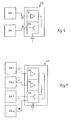
- FIG. 5 the arrangement according to FIG. 4 is expanded in that several Receive antennas EA1 to EAn and several transmit antennas SA1 to SAm are provided. Due to the multiple antennas, several can be targeted Radio equipment that may be at different distances in the radio area and below are oriented at different angles to the station under consideration, capture or aim at the same time. By using several directed Antennas can also be hidden from interference.
- a plurality of directional antennas can also advantageously be used as receiving antennas in connection with an omnidirectional antenna as a transmitting antenna be used.
- the line branch is in the case of several antennas As a rule, the structure is more complex and can also be carried out in several stages. For example in such a way that it is directly connected to the first connection AG is a circulator, which is divided into transmission branches and reception branches causes, and then another in the transmission and / or reception branch Division into several partial routes according to several individual antennas single-stage or multi-stage power dividers.
- the Signal paths of several or all receiving antennas from the connections AE1, ... AEn first combined in a coupler and then via a common one Amplifiers of the line branch are fed.
- FIG. 6 shows a further advantageous embodiment of a transmission device outlines in which instead of the embodiment of FIG. 3 instead of the attenuator in the first signal path in the transmission signal direction acting amplifier VS is arranged.
- Such an embodiment is particular advantageous when using a transmitting antenna with an antenna gain less than 0 dBd, for example an omnidirectional one Cross dipole antenna.
- the transmit signal amplifier too when using such an antenna and a common one, for example one tuned in the transmission power to a dipole antenna with 0 dBd Transceiver the permissible transmission power in a radio system, for example fully according to the European standard mentioned at the beginning exhausted and thus the range can be increased.
- a transmission device is in radio systems with leakage cable antennas or similar weak radiating antennas, for example for Radio communication in buildings, given where by the transmission device 6 the range can be increased.
- Advantageously used can be a transmission device of the type sketched in Fig. 6 finally, generally to increase the transmission range also in systems without restriction of the emitted transmission power.
- 7 is one Another embodiment of a transmission device with a transmission signal amplifier VS for connection to a common transceiver antenna SEA outlined similar to the embodiment of FIG. 2.
- SEA common transceiver antenna
- the transmission device outlined in FIG. 7 is in particular advantageous for increasing the transmission range. It basically applies the same considerations as for the transmission device according to FIG. 6.
- the power supply to the amplifier can be, for example, via a direct current signal on the radio frequency line from the transceiver.
Landscapes
- Engineering & Computer Science (AREA)
- Computer Networks & Wireless Communication (AREA)
- Signal Processing (AREA)
- Transmitters (AREA)
- Transceivers (AREA)
- Variable-Direction Aerials And Aerial Arrays (AREA)
- Mobile Radio Communication Systems (AREA)
Priority Applications (1)
| Application Number | Priority Date | Filing Date | Title |
|---|---|---|---|
| DE29824591U DE29824591U1 (de) | 1997-04-11 | 1998-04-02 | Funk-Kommunikations-Anordnung und Übertragungseinrichtung |
Applications Claiming Priority (4)
| Application Number | Priority Date | Filing Date | Title |
|---|---|---|---|
| DE29706463U DE29706463U1 (de) | 1997-04-11 | 1997-04-11 | Aktiv-Modul zur Entkopplung von Sende- u. Empfangsantenne |
| DE29706463U | 1997-04-11 | ||
| DE19745327A DE19745327A1 (de) | 1997-04-11 | 1997-10-14 | Funk-Kommunikations-Anordnung und Übertragungseinrichtung |
| DE19745327 | 1997-10-14 |
Publications (3)
| Publication Number | Publication Date |
|---|---|
| EP0874473A2 true EP0874473A2 (fr) | 1998-10-28 |
| EP0874473A3 EP0874473A3 (fr) | 2002-06-26 |
| EP0874473B1 EP0874473B1 (fr) | 2005-06-15 |
Family
ID=26040812
Family Applications (1)
| Application Number | Title | Priority Date | Filing Date |
|---|---|---|---|
| EP98105998A Expired - Lifetime EP0874473B1 (fr) | 1997-04-11 | 1998-04-02 | Système de réglage de puissance pour un dispositif de radiocommunication |
Country Status (2)
| Country | Link |
|---|---|
| EP (1) | EP0874473B1 (fr) |
| AT (1) | ATE298152T1 (fr) |
Cited By (2)
| Publication number | Priority date | Publication date | Assignee | Title |
|---|---|---|---|---|
| EP0991198A3 (fr) * | 1998-10-01 | 2003-05-14 | Matsushita Electric Industrial Co., Ltd. | Emetteur-récepteur avec une antenne utilisé à la fois pour émission et réception de signaux |
| WO2024099523A1 (fr) * | 2022-11-08 | 2024-05-16 | Continental Automotive Technologies GmbH | Compensateur, en particulier pour un véhicule automobile, module de communication, système de communication, et procédé |
Family Cites Families (4)
| Publication number | Priority date | Publication date | Assignee | Title |
|---|---|---|---|---|
| FI90703C (fi) * | 1992-02-14 | 1994-03-10 | Nokia Mobile Phones Ltd | Diversiteettiboosteri |
| WO1994018761A1 (fr) * | 1993-02-05 | 1994-08-18 | Kabushiki Kaisha Toshiba | Telephone sans fil |
| US5737687A (en) * | 1995-03-01 | 1998-04-07 | Qualcomm Incorporated | Self-attenuating RF transceiver system using antenna and modem interfaces and cable link |
| DE19547288C2 (de) * | 1995-12-18 | 1999-03-18 | Siemens Ag | Funkstation mit einer abgesetzten Antenneneinheit |
-
1998
- 1998-04-02 EP EP98105998A patent/EP0874473B1/fr not_active Expired - Lifetime
- 1998-04-02 AT AT98105998T patent/ATE298152T1/de not_active IP Right Cessation
Cited By (2)
| Publication number | Priority date | Publication date | Assignee | Title |
|---|---|---|---|---|
| EP0991198A3 (fr) * | 1998-10-01 | 2003-05-14 | Matsushita Electric Industrial Co., Ltd. | Emetteur-récepteur avec une antenne utilisé à la fois pour émission et réception de signaux |
| WO2024099523A1 (fr) * | 2022-11-08 | 2024-05-16 | Continental Automotive Technologies GmbH | Compensateur, en particulier pour un véhicule automobile, module de communication, système de communication, et procédé |
Also Published As
| Publication number | Publication date |
|---|---|
| EP0874473A3 (fr) | 2002-06-26 |
| ATE298152T1 (de) | 2005-07-15 |
| EP0874473B1 (fr) | 2005-06-15 |
Similar Documents
| Publication | Publication Date | Title |
|---|---|---|
| DE69225510T2 (de) | Modulbauförmiges Antennensystem mit verteilten Elementen | |
| DE69529559T2 (de) | Halbduplexfunkgerät mit niedriger Dämpfung des Sendesignals | |
| DE69934041T2 (de) | Spreizspektrumempfangsgerät mit Pfad- und Raumdiversität | |
| DE19617140C2 (de) | Funkstation zum Senden und Empfangen digitaler Informationen in einem Mobil-Kommunikationssystem | |
| DE69206333T2 (de) | Antennenkombination für den Empfang von Signalen von Satelliten und Bodenstationen, insbesondere für den Empfang von digitalen Ton-Rundfunksignalen. | |
| EP2101279A2 (fr) | Circuit réglable et unité de lecteur RFID | |
| DE69211330T2 (de) | Funksende- und -empfangsanordnung | |
| DE4322863A1 (de) | Mobilfunkantennenanlage | |
| DE102019104458B4 (de) | Repeater-System | |
| DE2528983C2 (de) | Fernmeldesystem | |
| DE69601044T2 (de) | Sende- und Empfangsgerät | |
| DE69933266T2 (de) | Doppelband Sender-Empfänger mit zwei Antennen | |
| DE19547288C2 (de) | Funkstation mit einer abgesetzten Antenneneinheit | |
| WO2001095507A2 (fr) | Agencement pour faire fonctionner plusieurs terminaux | |
| EP0874473B1 (fr) | Système de réglage de puissance pour un dispositif de radiocommunication | |
| DE19913064C1 (de) | Schaltungsanordnung zur Dämpfungskompensation | |
| DE19745327A1 (de) | Funk-Kommunikations-Anordnung und Übertragungseinrichtung | |
| DE60033903T2 (de) | Sendeempfangsgerät für Vollduplex von Signalen enthaltend ein rauscharmer Verstärker | |
| DE29824591U1 (de) | Funk-Kommunikations-Anordnung und Übertragungseinrichtung | |
| EP0438094B1 (fr) | Dispositif pour l'utilisation de téléphones sans fil | |
| EP1932246B1 (fr) | Circuit d'emission-reception pour canaux de reception et canaux d'emission se chevauchant | |
| DE102010018509B4 (de) | Senden und Empfangen von Funksignalen in verschiedenen Frequenzbereichen | |
| DE1441799A1 (de) | Leitungsnetzwerk zum Einfuegen in eine Antennenleitung | |
| DE19503440C2 (de) | Anordnung zur Übertragung, zur Abstrahlung und zum Empfang von Hochfrequenz-Signalen | |
| DE102013111798B4 (de) | Duplexer |
Legal Events
| Date | Code | Title | Description |
|---|---|---|---|
| PUAI | Public reference made under article 153(3) epc to a published international application that has entered the european phase |
Free format text: ORIGINAL CODE: 0009012 |
|
| AK | Designated contracting states |
Kind code of ref document: A2 Designated state(s): AT BE CH CY DE DK ES FI FR GB GR IE IT LI LU MC NL PT SE |
|
| AX | Request for extension of the european patent |
Free format text: AL;LT;LV;MK;RO;SI |
|
| PUAL | Search report despatched |
Free format text: ORIGINAL CODE: 0009013 |
|
| AK | Designated contracting states |
Kind code of ref document: A3 Designated state(s): AT BE CH CY DE DK ES FI FR GB GR IE IT LI LU MC NL PT SE |
|
| AX | Request for extension of the european patent |
Free format text: AL;LT;LV;MK;RO;SI |
|
| RIC1 | Information provided on ipc code assigned before grant |
Free format text: 7H 04B 7/005 A, 7H 03G 3/20 B, 7H 01Q 1/00 B, 7H 01Q 1/52 B |
|
| 17P | Request for examination filed |
Effective date: 20021227 |
|
| AKX | Designation fees paid |
Designated state(s): AT BE CH CY DE DK ES FI FR GB GR IE IT LI LU MC NL PT SE |
|
| 17Q | First examination report despatched |
Effective date: 20030303 |
|
| GRAP | Despatch of communication of intention to grant a patent |
Free format text: ORIGINAL CODE: EPIDOSNIGR1 |
|
| GRAS | Grant fee paid |
Free format text: ORIGINAL CODE: EPIDOSNIGR3 |
|
| GRAA | (expected) grant |
Free format text: ORIGINAL CODE: 0009210 |
|
| AK | Designated contracting states |
Kind code of ref document: B1 Designated state(s): AT BE CH CY DE DK ES FI FR GB GR IE IT LI LU MC NL PT SE |
|
| PG25 | Lapsed in a contracting state [announced via postgrant information from national office to epo] |
Ref country code: NL Free format text: LAPSE BECAUSE OF FAILURE TO SUBMIT A TRANSLATION OF THE DESCRIPTION OR TO PAY THE FEE WITHIN THE PRESCRIBED TIME-LIMIT Effective date: 20050615 Ref country code: IT Free format text: LAPSE BECAUSE OF FAILURE TO SUBMIT A TRANSLATION OF THE DESCRIPTION OR TO PAY THE FEE WITHIN THE PRESCRIBED TIME-LIMIT;WARNING: LAPSES OF ITALIAN PATENTS WITH EFFECTIVE DATE BEFORE 2007 MAY HAVE OCCURRED AT ANY TIME BEFORE 2007. THE CORRECT EFFECTIVE DATE MAY BE DIFFERENT FROM THE ONE RECORDED. Effective date: 20050615 Ref country code: FI Free format text: LAPSE BECAUSE OF FAILURE TO SUBMIT A TRANSLATION OF THE DESCRIPTION OR TO PAY THE FEE WITHIN THE PRESCRIBED TIME-LIMIT Effective date: 20050615 |
|
| REG | Reference to a national code |
Ref country code: GB Ref legal event code: FG4D Free format text: NOT ENGLISH Ref country code: CH Ref legal event code: EP |
|
| REF | Corresponds to: |
Ref document number: 59812860 Country of ref document: DE Date of ref document: 20050721 Kind code of ref document: P |
|
| REG | Reference to a national code |
Ref country code: IE Ref legal event code: FG4D Free format text: LANGUAGE OF EP DOCUMENT: GERMAN |
|
| REG | Reference to a national code |
Ref country code: CH Ref legal event code: NV Representative=s name: RIEDERER HASLER & PARTNER PATENTANWAELTE AG |
|
| PG25 | Lapsed in a contracting state [announced via postgrant information from national office to epo] |
Ref country code: SE Free format text: LAPSE BECAUSE OF FAILURE TO SUBMIT A TRANSLATION OF THE DESCRIPTION OR TO PAY THE FEE WITHIN THE PRESCRIBED TIME-LIMIT Effective date: 20050915 Ref country code: GR Free format text: LAPSE BECAUSE OF FAILURE TO SUBMIT A TRANSLATION OF THE DESCRIPTION OR TO PAY THE FEE WITHIN THE PRESCRIBED TIME-LIMIT Effective date: 20050915 Ref country code: DK Free format text: LAPSE BECAUSE OF FAILURE TO SUBMIT A TRANSLATION OF THE DESCRIPTION OR TO PAY THE FEE WITHIN THE PRESCRIBED TIME-LIMIT Effective date: 20050915 |
|
| GBT | Gb: translation of ep patent filed (gb section 77(6)(a)/1977) |
Effective date: 20050831 |
|
| PG25 | Lapsed in a contracting state [announced via postgrant information from national office to epo] |
Ref country code: ES Free format text: LAPSE BECAUSE OF FAILURE TO SUBMIT A TRANSLATION OF THE DESCRIPTION OR TO PAY THE FEE WITHIN THE PRESCRIBED TIME-LIMIT Effective date: 20050926 |
|
| PG25 | Lapsed in a contracting state [announced via postgrant information from national office to epo] |
Ref country code: PT Free format text: LAPSE BECAUSE OF FAILURE TO SUBMIT A TRANSLATION OF THE DESCRIPTION OR TO PAY THE FEE WITHIN THE PRESCRIBED TIME-LIMIT Effective date: 20051123 |
|
| NLV1 | Nl: lapsed or annulled due to failure to fulfill the requirements of art. 29p and 29m of the patents act | ||
| ET | Fr: translation filed | ||
| PGFP | Annual fee paid to national office [announced via postgrant information from national office to epo] |
Ref country code: FR Payment date: 20060420 Year of fee payment: 9 |
|
| PGFP | Annual fee paid to national office [announced via postgrant information from national office to epo] |
Ref country code: LU Payment date: 20060424 Year of fee payment: 9 |
|
| PGFP | Annual fee paid to national office [announced via postgrant information from national office to epo] |
Ref country code: IE Payment date: 20060426 Year of fee payment: 9 Ref country code: GB Payment date: 20060426 Year of fee payment: 9 Ref country code: BE Payment date: 20060426 Year of fee payment: 9 |
|
| PG25 | Lapsed in a contracting state [announced via postgrant information from national office to epo] |
Ref country code: MC Free format text: LAPSE BECAUSE OF NON-PAYMENT OF DUE FEES Effective date: 20060430 |
|
| PGFP | Annual fee paid to national office [announced via postgrant information from national office to epo] |
Ref country code: DE Payment date: 20060430 Year of fee payment: 9 |
|
| PLBE | No opposition filed within time limit |
Free format text: ORIGINAL CODE: 0009261 |
|
| STAA | Information on the status of an ep patent application or granted ep patent |
Free format text: STATUS: NO OPPOSITION FILED WITHIN TIME LIMIT |
|
| 26N | No opposition filed |
Effective date: 20060316 |
|
| PGFP | Annual fee paid to national office [announced via postgrant information from national office to epo] |
Ref country code: AT Payment date: 20070423 Year of fee payment: 10 |
|
| PGFP | Annual fee paid to national office [announced via postgrant information from national office to epo] |
Ref country code: CH Payment date: 20070424 Year of fee payment: 10 |
|
| GBPC | Gb: european patent ceased through non-payment of renewal fee |
Effective date: 20070402 |
|
| BERE | Be: lapsed |
Owner name: *PAULUS PATRICK Effective date: 20070430 |
|
| PG25 | Lapsed in a contracting state [announced via postgrant information from national office to epo] |
Ref country code: DE Free format text: LAPSE BECAUSE OF NON-PAYMENT OF DUE FEES Effective date: 20071101 |
|
| REG | Reference to a national code |
Ref country code: IE Ref legal event code: MM4A |
|
| PG25 | Lapsed in a contracting state [announced via postgrant information from national office to epo] |
Ref country code: BE Free format text: LAPSE BECAUSE OF NON-PAYMENT OF DUE FEES Effective date: 20070430 |
|
| PG25 | Lapsed in a contracting state [announced via postgrant information from national office to epo] |
Ref country code: GB Free format text: LAPSE BECAUSE OF NON-PAYMENT OF DUE FEES Effective date: 20070402 |
|
| PG25 | Lapsed in a contracting state [announced via postgrant information from national office to epo] |
Ref country code: IE Free format text: LAPSE BECAUSE OF NON-PAYMENT OF DUE FEES Effective date: 20070402 |
|
| PG25 | Lapsed in a contracting state [announced via postgrant information from national office to epo] |
Ref country code: FR Free format text: LAPSE BECAUSE OF NON-PAYMENT OF DUE FEES Effective date: 20070430 |
|
| PG25 | Lapsed in a contracting state [announced via postgrant information from national office to epo] |
Ref country code: CY Free format text: LAPSE BECAUSE OF FAILURE TO SUBMIT A TRANSLATION OF THE DESCRIPTION OR TO PAY THE FEE WITHIN THE PRESCRIBED TIME-LIMIT Effective date: 20050615 |
|
| REG | Reference to a national code |
Ref country code: CH Ref legal event code: PL |
|
| PG25 | Lapsed in a contracting state [announced via postgrant information from national office to epo] |
Ref country code: LI Free format text: LAPSE BECAUSE OF NON-PAYMENT OF DUE FEES Effective date: 20080430 Ref country code: CH Free format text: LAPSE BECAUSE OF NON-PAYMENT OF DUE FEES Effective date: 20080430 |
|
| PG25 | Lapsed in a contracting state [announced via postgrant information from national office to epo] |
Ref country code: AT Free format text: LAPSE BECAUSE OF NON-PAYMENT OF DUE FEES Effective date: 20080402 |
|
| PG25 | Lapsed in a contracting state [announced via postgrant information from national office to epo] |
Ref country code: LU Free format text: LAPSE BECAUSE OF NON-PAYMENT OF DUE FEES Effective date: 20070402 |