EP0874482A2 - Dispositif pour l'émission et réception de signaux optiques - Google Patents
Dispositif pour l'émission et réception de signaux optiques Download PDFInfo
- Publication number
- EP0874482A2 EP0874482A2 EP98100371A EP98100371A EP0874482A2 EP 0874482 A2 EP0874482 A2 EP 0874482A2 EP 98100371 A EP98100371 A EP 98100371A EP 98100371 A EP98100371 A EP 98100371A EP 0874482 A2 EP0874482 A2 EP 0874482A2
- Authority
- EP
- European Patent Office
- Prior art keywords
- optical
- receiving device
- optical fiber
- transmitting
- optical signals
- Prior art date
- Legal status (The legal status is an assumption and is not a legal conclusion. Google has not performed a legal analysis and makes no representation as to the accuracy of the status listed.)
- Granted
Links
- 230000003287 optical effect Effects 0.000 title claims abstract description 70
- 239000013307 optical fiber Substances 0.000 claims abstract description 49
- 230000005540 biological transmission Effects 0.000 claims abstract description 18
- 230000002457 bidirectional effect Effects 0.000 claims description 11
- 229920005594 polymer fiber Polymers 0.000 claims description 2
- 238000001914 filtration Methods 0.000 abstract description 2
- 230000008878 coupling Effects 0.000 description 11
- 238000010168 coupling process Methods 0.000 description 11
- 238000005859 coupling reaction Methods 0.000 description 11
- 238000002834 transmittance Methods 0.000 description 2
- 230000006978 adaptation Effects 0.000 description 1
- 238000013459 approach Methods 0.000 description 1
- 238000013016 damping Methods 0.000 description 1
- 230000006735 deficit Effects 0.000 description 1
- 230000006866 deterioration Effects 0.000 description 1
- 230000000694 effects Effects 0.000 description 1
- 239000000835 fiber Substances 0.000 description 1
- 230000001771 impaired effect Effects 0.000 description 1
- 238000000926 separation method Methods 0.000 description 1
- 230000008054 signal transmission Effects 0.000 description 1
Images

Classifications
-
- H—ELECTRICITY
- H04—ELECTRIC COMMUNICATION TECHNIQUE
- H04B—TRANSMISSION
- H04B10/00—Transmission systems employing electromagnetic waves other than radio-waves, e.g. infrared, visible or ultraviolet light, or employing corpuscular radiation, e.g. quantum communication
- H04B10/40—Transceivers
Definitions
- the invention relates to an arrangement for transmitting and Receive optical signals with at least one Transmitting device and at least one receiving device and an optical fiber for transmitting the optical signals.
- Arrangements of the generic type are known. These are used to generate optical signals to transmit over a transmission link.
- at least one optical fiber is provided the ends of which each have at least one transmitting device and at least one receiving device is provided are.
- the Bidirectional data transmission can be done with both single-mode fiber systems as well as with multi-mode optical fiber systems respectively.
- the transfer of the Signals can be either a wavelength or different wavelengths.
- special optical components for example beam splitting Couplers with downstream filters or wavelength dividing ends Coupler, known.
- the disadvantage here is that through the special optical components on the one hand there is an additional space requirement and on the other hand, relatively high power losses due to a damping effect of the special optical components occur.
- the invention has for its object an arrangement of the generic type to create the simple is built, works reliably and relatively has low power losses.
- this object is achieved by means of an arrangement solved with the features mentioned in claim l.
- the transmitting device and the receiving device directly an optical effective area the optical fiber are assigned, the intermediate switching additional special optical components unnecessary.
- optical fibers with a relatively large cross-section can be a direct one Coupling of the transmitting device and the receiving device to an end face of the optical fiber take place because known components for sending and Receive optical signals, for example laser diodes or superluminescent diodes a relatively small one Have size that does not have a cross section out of the optical fiber.
- the optical fiber is greater than the sum of the Cross sections of the optical active surfaces of the transmitter and the receiving device, is an uncritical one Coupling of the optical signals to be transmitted, as well as for bidirectional transmission necessary directivity can be achieved easily.
- a cross section of the optical active surface of the receiving device can preferably also be of similar size or larger than the optical effective area of the optical fiber be, as a result of the coupling of the signals is not affected.
- the transmitting device and the receiving device are positioned side by side.
- the entire available optical effective area of the optical fiber in an area for the receiving device and divided an area for the transmitter is without the effectiveness of the arrangement is impaired.
- Adaptation of the cross-sections of the receiving device and the transmitter cannot usable optical effective area of the optical fiber relative be kept small.
- the receiving device and the Transmitting device are arranged one above the other, wherein the transmitting device between the optical active surface the optical fiber and the receiving device lies.
- the cross section of the optical fiber be used to the maximum.
- a performance impairment through the front of the receiving facility lying transmitter is on a negligible Minimum reduced.
- a filter is assigned, its optical effective cross-sectional area of the receiving device is adjusted. So without much additional effort a wavelength division multiplexing (WDM) operation to increase the dynamics of the entire arrangement achievable.
- WDM wavelength division multiplexing
- FIG 1 shows schematically an overall view of a Arrangement 10 for bidirectional optical transmission Signals.
- the arrangement 10 comprises a transmission link 12, which is formed by an optical fiber 14 is.
- the optical fiber 14 can be, for example Single-mode optical fiber or a multi-mode optical fiber be.
- an optical polymer fiber used with a diameter of 1 mm At the end points of the transmission path 12 are each a transceiver 16 is arranged, each here indicated receiving devices 18 and transmitting devices 20 have.
- a bidirectional transmission optical signals can either be with a Wavelength or with different wavelengths, a so-called wavelength division multiplex (WDM).
- WDM wavelength division multiplex
- FIG. 1 A coupling point 24 between the Optical fiber 14 and the transceivers 16 explained in more detail.
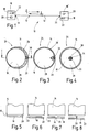
- Figures 2 to 4 each show top views to the coupling point 24 - from the point of view the transceiver 16 in the direction of the optical fiber 14.
- the receiving device 18 and the transmitting device 20 are arranged such that a area coverage of an optical effective area 26, here the end face, the optical fiber 14 with the optically active surfaces 28 of the receiving device 18 and 30 of the transmitting device 20 is.
- the sum of the optical active surfaces 28 and 30 is smaller than the optical effective area 26.
- a receiving device 18 is a pin photodiode, for example and as a transmitting device 20, for example a laser diode is used.
- the receiving device 18 and the transmitter 20 side by side quasi from the optical effective area 26 of the optical fiber 14 are covered is a Coupling the optical signals from both Transmitter 20 in the optical fiber as well from the optical fiber 14 into the receiving device 18 not critical.
- the receiving device 18 in essentially the entire optical active surface 26 of the Optical fiber 14 covers, this practically receives the total received performance.
- the loss area that by the difference between the optical effective area 26 of the optical fiber 14 and the optical Effective area 28 of the receiving device 18 results negligible small.
- Figures 3 and 4 show further variants the arrangement of the receiving device 18 and the Transmitting device 20. According to FIG. 3, this is optical effective area 28 of the receiving device 18 further the optically active surface 26 of the optical fiber 14 customized.
- the receiving device 18 only has a section 32 of the arrangement of the transmitter 20 serves.
- Arrangement is the difference between the optical Active surface 26 of the optical fiber 14 and the optical Active area 28 of the receiving device 18 further reduced so that the power loss of the transmitting optical signals is minimized again.
- a this power loss is minimized again.
- the transmitting device 20 preferably centric, in a preferably circular recess 34 of the receiving device 18 arranged. It only a narrow gap 36 remains between the receiving device 18 and the transmitting device 20, so that the loss area by the Diameter of the recess 34 is given.
- FIG Figures 5 to 8 show top views of the coupling point 24 along the section line I / I according to FIG Figures 2 to 4. Same parts as in the previous Figures are given the same reference numerals and not explained again.
- FIG. 5 shows the top view according to FIG. 2, it becoming clear that the receiving device 18th and the transmitter 20 directly the optical Active surface 26, here the end face, the optical fiber 14 face each other.
- the filter 22 is additionally arranged between the receiving device 18 and the optical fiber 14.
- the filter 22 is designed so that optical signals of the wavelength ⁇ 2 of the opposite transceiver 16 are passed, while optical signals of the wavelength ⁇ 1 of the own transmitter 20 are blocked. It is thereby achieved that optical signals reflected back from the optical fiber 14, in particular from its optical active surface 26, do not reach the "own" receiving device 18. This reduces so-called near-end crosstalk.
- FIG 7 shows the arrangement of Figure 4, here the filter 22 also has the recess 34, so that the transmitter 20 optical signals in the optical fiber 14 can couple.
- FIG. 8 shows a preferred embodiment variant in which the receiving device 18 and the transmitting device 20 are not positioned next to one another (as shown in FIGS. 2 to 7), but rather the receiving device 18 and the transmitting device 20 are positioned one above the other.
- the transmitting device 20 is arranged, as it were, between the filter 22 assigned to the receiving device 18 and the optical fiber 14. This ensures that the optical loss surface for coupling optical signals from the optical fiber 14 to the receiving device 18 remains limited to the actual optical active surface 30 of the transmitting device 20. Because this has a very small effective area, the receiver 18 receives practically all the power received.
- the power loss approaches zero and is at most in the range of about 0.5 dB, when a diameter of the transmission device 20, for example, 1/3 corresponds to a diameter of the optical fiber fourteenth
- FIG. 9 shows the arrangement 10 with two transceivers 16, 16 'according to the exemplary embodiment shown in FIG. 8.
- the filter 22 of the transceiver 16 is blocked for optical signals of the optical signals of the wavelength ⁇ 1 emitted by the transmitter 20 of the transceiver 16, while optical signals of the wavelength ⁇ 2 which are emitted by the transmitter 20 'of the transceiver 16' are transmitted.
- the transmittance of the filter 22 'of the transceiver 16' shown in FIG. 9b is transparent especially for the optical signals of the wavelength ⁇ 1 of the transmitter 20 of the transceiver 16, while it is for optical signals of the wavelength ⁇ 2 of the transmitter 20 'of the transceiver 16' locks.
- WDM wavelength division multiplex
- FIG. 10 illustrates the relative level ratios which arise during a bidirectional operation of the arrangement 10 shown in FIG.
- the powers of the optical signals of the wavelengths ⁇ 1 and ⁇ 2 are shown in each case.
- the starting situation is that optical signals of the wavelengths ⁇ 1 and ⁇ 2 are coupled into the optical fiber 14 with the maximum given power by the transmitting devices 20, 20 '. Since the power loss is 0 at this time, the relative level is 0 dB. Transmission losses during the transmission of the optical signals via the transmission link 12 result in performance losses in the optical signals received at the respective opposite receiving devices 18. These power losses are influenced, inter alia, by the so-called near-end crosstalk losses 40 and 42, respectively.
- reflections arise which are determined, for example, by the end face (optical active area 26) of the optical fiber 14.
Landscapes
- Physics & Mathematics (AREA)
- Electromagnetism (AREA)
- Engineering & Computer Science (AREA)
- Computer Networks & Wireless Communication (AREA)
- Signal Processing (AREA)
- Optical Couplings Of Light Guides (AREA)
- Optical Communication System (AREA)
- Bidirectional Digital Transmission (AREA)
Applications Claiming Priority (2)
| Application Number | Priority Date | Filing Date | Title |
|---|---|---|---|
| DE19716838 | 1997-04-22 | ||
| DE19716838A DE19716838A1 (de) | 1997-04-22 | 1997-04-22 | Anordnung zum Senden und Empfangen optischer Signale |
Publications (3)
| Publication Number | Publication Date |
|---|---|
| EP0874482A2 true EP0874482A2 (fr) | 1998-10-28 |
| EP0874482A3 EP0874482A3 (fr) | 2004-01-14 |
| EP0874482B1 EP0874482B1 (fr) | 2006-05-24 |
Family
ID=7827304
Family Applications (1)
| Application Number | Title | Priority Date | Filing Date |
|---|---|---|---|
| EP98100371A Expired - Lifetime EP0874482B1 (fr) | 1997-04-22 | 1998-01-12 | Dispositif pour l'émission et réception de signaux optiques |
Country Status (5)
| Country | Link |
|---|---|
| US (1) | US5933553A (fr) |
| EP (1) | EP0874482B1 (fr) |
| AT (1) | ATE327605T1 (fr) |
| CA (1) | CA2234961A1 (fr) |
| DE (2) | DE19716838A1 (fr) |
Families Citing this family (6)
| Publication number | Priority date | Publication date | Assignee | Title |
|---|---|---|---|---|
| JP2000111755A (ja) * | 1998-10-06 | 2000-04-21 | Mitsubishi Gas Chem Co Inc | 波長多重化部品 |
| US6973268B1 (en) | 2000-06-30 | 2005-12-06 | Lucent Technologies Inc. | Bi-directional optical transmission using dual channel bands |
| US7653315B2 (en) * | 2003-01-21 | 2010-01-26 | Gateway, Inc. | Bi-directional optical monitor interconnect |
| US6952519B2 (en) * | 2003-05-02 | 2005-10-04 | Corning Incorporated | Large effective area high SBS threshold optical fiber |
| US7082243B2 (en) * | 2004-04-05 | 2006-07-25 | Corning Incorporated | Large effective area high SBS threshold optical fiber |
| US6959135B1 (en) * | 2004-12-21 | 2005-10-25 | Corning Incorporated | SBS suppressed nonlinear optical fiber |
Family Cites Families (13)
| Publication number | Priority date | Publication date | Assignee | Title |
|---|---|---|---|---|
| US3859536A (en) * | 1974-01-07 | 1975-01-07 | Corning Glass Works | Optical communication system source-detector pair |
| GB1538485A (en) * | 1976-01-07 | 1979-01-17 | Rank Organisation Ltd | Opto-electric device |
| GB2011610A (en) * | 1977-12-23 | 1979-07-11 | Elliot Bros Ltd | Fibre optic terminal |
| DE3500532A1 (de) * | 1985-01-07 | 1986-07-10 | Heinrich-Hertz-Institut für Nachrichtentechnik Berlin GmbH, 1000 Berlin | Muldex fuer optische uebertragungssysteme |
| DE3538035A1 (de) * | 1985-10-25 | 1987-04-30 | Siemens Ag | Rotierende datenuebertragungsvorrichtung |
| DE3637097A1 (de) * | 1986-10-31 | 1988-05-05 | Standard Elektrik Lorenz Ag | Optisches breitband-nachrichtenuebertragungssystem, insbesondere im teilnehmeranschlussbereich |
| EP0290242A3 (fr) * | 1987-05-08 | 1989-05-03 | Simmonds Precision Products Inc. | Emetteur/détecteur pour des systèmes à fibre optique |
| DE8804626U1 (de) * | 1988-04-08 | 1988-06-01 | Cmc Carl Maier + Cie Ag, Schaffhausen | Elektro-optischer Umsetzer |
| DE4209797A1 (de) * | 1991-04-26 | 1992-10-29 | Kommunikations Elektronik | Verfahren zur bidirektionalen datenuebertragung |
| US5555334A (en) * | 1993-10-07 | 1996-09-10 | Hitachi, Ltd. | Optical transmission and receiving module and optical communication system using the same |
| JP2606613B2 (ja) * | 1994-12-28 | 1997-05-07 | 日本電気株式会社 | 無線選択呼出受信機のデータ書込方式 |
| DE19534936C2 (de) * | 1995-09-20 | 1997-09-11 | Siemens Ag | Optoelektronische Sende-Empfangs-Vorrichtung |
| US5809187A (en) * | 1997-04-24 | 1998-09-15 | Boeing North American, Inc. | Multi-port network using passive optical couplers |
-
1997
- 1997-04-22 DE DE19716838A patent/DE19716838A1/de not_active Ceased
-
1998
- 1998-01-12 EP EP98100371A patent/EP0874482B1/fr not_active Expired - Lifetime
- 1998-01-12 AT AT98100371T patent/ATE327605T1/de not_active IP Right Cessation
- 1998-01-12 DE DE59813546T patent/DE59813546D1/de not_active Expired - Lifetime
- 1998-04-20 CA CA002234961A patent/CA2234961A1/fr not_active Abandoned
- 1998-04-22 US US09/064,435 patent/US5933553A/en not_active Expired - Fee Related
Also Published As
| Publication number | Publication date |
|---|---|
| CA2234961A1 (fr) | 1998-10-22 |
| US5933553A (en) | 1999-08-03 |
| EP0874482B1 (fr) | 2006-05-24 |
| ATE327605T1 (de) | 2006-06-15 |
| EP0874482A3 (fr) | 2004-01-14 |
| DE59813546D1 (de) | 2006-06-29 |
| DE19716838A1 (de) | 1998-10-29 |
Similar Documents
| Publication | Publication Date | Title |
|---|---|---|
| DE69915307T2 (de) | Bidirektionale dispersionskompensationsvorrichtung | |
| EP1425619B1 (fr) | Ensemble emetteur-recepteur pour transmission de donnees optique bidirectionnelle | |
| DE69426426T2 (de) | Optisches bidirektionales Kommunikationssystem mit Wellenlängenmultiplex | |
| DE69005794T2 (de) | Optische Verstärkungseinrichtung mit niedrigem Rauschen und Reflexion der Pumpleistung. | |
| DE10037902C2 (de) | Optisches bidirektionales Sende- und Empfangsmodul mit einem Stiftkörper mit integriertem WDM-Filter | |
| EP0354567B1 (fr) | Ensemble émission-réception pour un système de communication bidirectionnel cohérent et optique | |
| DE60026497T2 (de) | Optische dicht-wdm-multiplexer und -demultiplexer | |
| DE69621871T2 (de) | Optisches Datenverbindungsverfahren und Vorrichtung dazu | |
| DE2333968C2 (de) | Fasernetz für die optoelektronische Datenübertragung | |
| DE69116396T2 (de) | Optischer Koppler | |
| EP0410143A2 (fr) | Dispositif d'émission et de réception optoélectrique | |
| DE19534936C2 (de) | Optoelektronische Sende-Empfangs-Vorrichtung | |
| DE60223398T2 (de) | Verfahren zum verbinden und prüfen von schnittstellen für faseroptische cwdm-systeme | |
| DE3230570A1 (de) | Sende- und empfangseinrichtung fuer ein faseroptisches sensorsystem | |
| EP0349766A2 (fr) | Système de transmission d'informations optique, concernant en particulier le raccordement d'abonnés | |
| DE69720450T2 (de) | Optische Dispersionskompensation | |
| EP0874482B1 (fr) | Dispositif pour l'émission et réception de signaux optiques | |
| WO2003027735A1 (fr) | Dispositif optique et module emetteur/recepteur destine a des systemes wdm optiques bidirectionnels et a des transmissions de donnees optiques | |
| DE69322962T2 (de) | Verfahren zur teilnehmerverbindungsherstellung und teilnehmernetzwerk | |
| DE19829632A1 (de) | Optisches Kommunikationsgerät und -verfahren | |
| EP0073314B1 (fr) | Système de transmission pour une utilisation multiple bidirectionnelle d'une fibre optique | |
| DE69019480T3 (de) | Adapter für verstärkte optische Leitungen. | |
| DE2611011A1 (de) | Optische koppelanordnung fuer systeme der optischen nachrichtentechnik | |
| EP1111740B1 (fr) | Procédé de transmission de pompage optique de puissance | |
| DE69829330T2 (de) | Zuverlässigkeitsverbesserung eines optischen Übertragungssystems und Verfahren geeignet dafür |
Legal Events
| Date | Code | Title | Description |
|---|---|---|---|
| PUAI | Public reference made under article 153(3) epc to a published international application that has entered the european phase |
Free format text: ORIGINAL CODE: 0009012 |
|
| AK | Designated contracting states |
Kind code of ref document: A2 Designated state(s): AT BE CH DE DK ES FI FR GB GR IE IT LI LU MC NL PT SE |
|
| AX | Request for extension of the european patent |
Free format text: AL;LT;LV;MK;RO;SI |
|
| PUAL | Search report despatched |
Free format text: ORIGINAL CODE: 0009013 |
|
| AK | Designated contracting states |
Kind code of ref document: A3 Designated state(s): AT BE CH DE DK ES FI FR GB GR IE IT LI LU MC NL PT SE |
|
| AX | Request for extension of the european patent |
Extension state: AL LT LV MK RO SI |
|
| 17P | Request for examination filed |
Effective date: 20040714 |
|
| AKX | Designation fees paid |
Designated state(s): AT BE CH DE DK ES FI FR GB GR IE IT LI LU MC NL PT SE |
|
| 17Q | First examination report despatched |
Effective date: 20041119 |
|
| GRAP | Despatch of communication of intention to grant a patent |
Free format text: ORIGINAL CODE: EPIDOSNIGR1 |
|
| GRAS | Grant fee paid |
Free format text: ORIGINAL CODE: EPIDOSNIGR3 |
|
| GRAA | (expected) grant |
Free format text: ORIGINAL CODE: 0009210 |
|
| AK | Designated contracting states |
Kind code of ref document: B1 Designated state(s): AT BE CH DE DK ES FI FR GB GR IE IT LI LU MC NL PT SE |
|
| PG25 | Lapsed in a contracting state [announced via postgrant information from national office to epo] |
Ref country code: IT Free format text: LAPSE BECAUSE OF FAILURE TO SUBMIT A TRANSLATION OF THE DESCRIPTION OR TO PAY THE FEE WITHIN THE PRESCRIBED TIME-LIMIT;WARNING: LAPSES OF ITALIAN PATENTS WITH EFFECTIVE DATE BEFORE 2007 MAY HAVE OCCURRED AT ANY TIME BEFORE 2007. THE CORRECT EFFECTIVE DATE MAY BE DIFFERENT FROM THE ONE RECORDED. Effective date: 20060524 Ref country code: IE Free format text: LAPSE BECAUSE OF FAILURE TO SUBMIT A TRANSLATION OF THE DESCRIPTION OR TO PAY THE FEE WITHIN THE PRESCRIBED TIME-LIMIT Effective date: 20060524 Ref country code: FI Free format text: LAPSE BECAUSE OF FAILURE TO SUBMIT A TRANSLATION OF THE DESCRIPTION OR TO PAY THE FEE WITHIN THE PRESCRIBED TIME-LIMIT Effective date: 20060524 |
|
| REG | Reference to a national code |
Ref country code: GB Ref legal event code: FG4D Free format text: NOT ENGLISH |
|
| REG | Reference to a national code |
Ref country code: CH Ref legal event code: EP |
|
| REG | Reference to a national code |
Ref country code: IE Ref legal event code: FG4D Free format text: LANGUAGE OF EP DOCUMENT: GERMAN |
|
| REF | Corresponds to: |
Ref document number: 59813546 Country of ref document: DE Date of ref document: 20060629 Kind code of ref document: P |
|
| PG25 | Lapsed in a contracting state [announced via postgrant information from national office to epo] |
Ref country code: SE Free format text: LAPSE BECAUSE OF FAILURE TO SUBMIT A TRANSLATION OF THE DESCRIPTION OR TO PAY THE FEE WITHIN THE PRESCRIBED TIME-LIMIT Effective date: 20060824 Ref country code: DK Free format text: LAPSE BECAUSE OF FAILURE TO SUBMIT A TRANSLATION OF THE DESCRIPTION OR TO PAY THE FEE WITHIN THE PRESCRIBED TIME-LIMIT Effective date: 20060824 |
|
| PG25 | Lapsed in a contracting state [announced via postgrant information from national office to epo] |
Ref country code: ES Free format text: LAPSE BECAUSE OF FAILURE TO SUBMIT A TRANSLATION OF THE DESCRIPTION OR TO PAY THE FEE WITHIN THE PRESCRIBED TIME-LIMIT Effective date: 20060904 |
|
| GBT | Gb: translation of ep patent filed (gb section 77(6)(a)/1977) |
Effective date: 20060817 |
|
| PG25 | Lapsed in a contracting state [announced via postgrant information from national office to epo] |
Ref country code: PT Free format text: LAPSE BECAUSE OF FAILURE TO SUBMIT A TRANSLATION OF THE DESCRIPTION OR TO PAY THE FEE WITHIN THE PRESCRIBED TIME-LIMIT Effective date: 20061024 |
|
| REG | Reference to a national code |
Ref country code: IE Ref legal event code: FD4D |
|
| ET | Fr: translation filed | ||
| PG25 | Lapsed in a contracting state [announced via postgrant information from national office to epo] |
Ref country code: MC Free format text: LAPSE BECAUSE OF NON-PAYMENT OF DUE FEES Effective date: 20070131 Ref country code: LI Free format text: LAPSE BECAUSE OF NON-PAYMENT OF DUE FEES Effective date: 20070131 Ref country code: CH Free format text: LAPSE BECAUSE OF NON-PAYMENT OF DUE FEES Effective date: 20070131 |
|
| PLBE | No opposition filed within time limit |
Free format text: ORIGINAL CODE: 0009261 |
|
| STAA | Information on the status of an ep patent application or granted ep patent |
Free format text: STATUS: NO OPPOSITION FILED WITHIN TIME LIMIT |
|
| 26N | No opposition filed |
Effective date: 20070227 |
|
| REG | Reference to a national code |
Ref country code: CH Ref legal event code: PL |
|
| REG | Reference to a national code |
Ref country code: FR Ref legal event code: ST Effective date: 20070930 |
|
| BERE | Be: lapsed |
Owner name: DEUTSCHE TELEKOM A.G. Effective date: 20070131 |
|
| PG25 | Lapsed in a contracting state [announced via postgrant information from national office to epo] |
Ref country code: BE Free format text: LAPSE BECAUSE OF NON-PAYMENT OF DUE FEES Effective date: 20070131 |
|
| REG | Reference to a national code |
Ref country code: FR Ref legal event code: D3 |
|
| PG25 | Lapsed in a contracting state [announced via postgrant information from national office to epo] |
Ref country code: GR Free format text: LAPSE BECAUSE OF FAILURE TO SUBMIT A TRANSLATION OF THE DESCRIPTION OR TO PAY THE FEE WITHIN THE PRESCRIBED TIME-LIMIT Effective date: 20060825 |
|
| PG25 | Lapsed in a contracting state [announced via postgrant information from national office to epo] |
Ref country code: AT Free format text: LAPSE BECAUSE OF NON-PAYMENT OF DUE FEES Effective date: 20070112 |
|
| PG25 | Lapsed in a contracting state [announced via postgrant information from national office to epo] |
Ref country code: LU Free format text: LAPSE BECAUSE OF NON-PAYMENT OF DUE FEES Effective date: 20070112 |
|
| PGFP | Annual fee paid to national office [announced via postgrant information from national office to epo] |
Ref country code: IT Payment date: 20100125 Year of fee payment: 13 Ref country code: FR Payment date: 20100209 Year of fee payment: 13 |
|
| PGFP | Annual fee paid to national office [announced via postgrant information from national office to epo] |
Ref country code: GB Payment date: 20100121 Year of fee payment: 13 |
|
| PGFP | Annual fee paid to national office [announced via postgrant information from national office to epo] |
Ref country code: NL Payment date: 20100121 Year of fee payment: 13 Ref country code: DE Payment date: 20100326 Year of fee payment: 13 |
|
| REG | Reference to a national code |
Ref country code: NL Ref legal event code: V1 Effective date: 20110801 |
|
| GBPC | Gb: european patent ceased through non-payment of renewal fee |
Effective date: 20110112 |
|
| REG | Reference to a national code |
Ref country code: FR Ref legal event code: ST Effective date: 20110930 |
|
| PG25 | Lapsed in a contracting state [announced via postgrant information from national office to epo] |
Ref country code: FR Free format text: LAPSE BECAUSE OF NON-PAYMENT OF DUE FEES Effective date: 20110131 |
|
| PG25 | Lapsed in a contracting state [announced via postgrant information from national office to epo] |
Ref country code: GB Free format text: LAPSE BECAUSE OF NON-PAYMENT OF DUE FEES Effective date: 20110112 |
|
| REG | Reference to a national code |
Ref country code: DE Ref legal event code: R119 Ref document number: 59813546 Country of ref document: DE Effective date: 20110802 |
|
| PG25 | Lapsed in a contracting state [announced via postgrant information from national office to epo] |
Ref country code: NL Free format text: LAPSE BECAUSE OF NON-PAYMENT OF DUE FEES Effective date: 20110801 Ref country code: IT Free format text: LAPSE BECAUSE OF NON-PAYMENT OF DUE FEES Effective date: 20110112 |
|
| PG25 | Lapsed in a contracting state [announced via postgrant information from national office to epo] |
Ref country code: DE Free format text: LAPSE BECAUSE OF NON-PAYMENT OF DUE FEES Effective date: 20110802 |