EP0354567B1 - Ensemble émission-réception pour un système de communication bidirectionnel cohérent et optique - Google Patents
Ensemble émission-réception pour un système de communication bidirectionnel cohérent et optique Download PDFInfo
- Publication number
- EP0354567B1 EP0354567B1 EP89114799A EP89114799A EP0354567B1 EP 0354567 B1 EP0354567 B1 EP 0354567B1 EP 89114799 A EP89114799 A EP 89114799A EP 89114799 A EP89114799 A EP 89114799A EP 0354567 B1 EP0354567 B1 EP 0354567B1
- Authority
- EP
- European Patent Office
- Prior art keywords
- frequency
- laser
- transceiver
- optical
- signal wave
- Prior art date
- Legal status (The legal status is an assumption and is not a legal conclusion. Google has not performed a legal analysis and makes no representation as to the accuracy of the status listed.)
- Expired - Lifetime
Links
- 230000003287 optical effect Effects 0.000 title claims abstract description 52
- 230000001427 coherent effect Effects 0.000 title claims abstract description 13
- 230000002457 bidirectional effect Effects 0.000 title claims abstract description 8
- 230000005855 radiation Effects 0.000 claims abstract description 9
- 230000005540 biological transmission Effects 0.000 claims description 24
- 230000008878 coupling Effects 0.000 claims 2
- 238000010168 coupling process Methods 0.000 claims 2
- 238000005859 coupling reaction Methods 0.000 claims 2
- 238000001514 detection method Methods 0.000 claims 2
- 238000003199 nucleic acid amplification method Methods 0.000 abstract description 8
- 230000003321 amplification Effects 0.000 abstract description 7
- 239000013307 optical fiber Substances 0.000 description 12
- 239000000835 fiber Substances 0.000 description 3
- 230000035945 sensitivity Effects 0.000 description 2
- 239000004020 conductor Substances 0.000 description 1
- 238000010276 construction Methods 0.000 description 1
- 230000000694 effects Effects 0.000 description 1
- 238000000034 method Methods 0.000 description 1
- 230000010355 oscillation Effects 0.000 description 1
- 230000001105 regulatory effect Effects 0.000 description 1
- 230000008054 signal transmission Effects 0.000 description 1
- 239000000758 substrate Substances 0.000 description 1
Images
Classifications
-
- H—ELECTRICITY
- H04—ELECTRIC COMMUNICATION TECHNIQUE
- H04B—TRANSMISSION
- H04B10/00—Transmission systems employing electromagnetic waves other than radio-waves, e.g. infrared, visible or ultraviolet light, or employing corpuscular radiation, e.g. quantum communication
- H04B10/40—Transceivers
Definitions
- the present invention relates to a transmitting / receiving part for a transmission system according to the preamble of claim 1.
- FIG. 2 shows a transmitting / receiving part with a single laser, which is used both for transmitting a signal carrier wave and for transmitting an oscillator radiation for the coherent -optical overlay receiver of the same transceiver, ie is used as a so-called "local oscillator".
- the laser is a laser that emits in two exit directions. One of its partial beams is coupled into the optical waveguide leading to the coherent-optical superimposed receiver by means of a coupler (optical combiner 3), and its other partial beam is coupled into the same optical waveguide in the direction of the remote station to transmit a signal carrier wave via the same coupler.
- the frequency of the intermediate frequency signal arising in the heterodyne receiver is predetermined, in the explained Example 600 MHz, and also the optical frequency of the partial beams input by the laser into the optical waveguide is regulated to a fixed value depending on the predetermined intermediate frequency, so that only signals with a single, predetermined optical frequency can be received with the optical superimposed receiver .
- the single coupler 3 to which both optical outputs of the laser are connected, provides an annular oscillator structure in which problems with resonance oscillations occur, optical isolators are present in the annular structure and are also necessary. Since these are very expensive optical components, the known transmitting / receiving part has the disadvantage of being considerably expensive. This is all the more disadvantageous since the reception frequency of the optical heterodyne receiver is fixed to a single optical frequency and it is therefore not possible to receive any optical frequency from a broad band of frequencies by tuning the receiver.
- the object of the present invention is therefore to provide a transmitting / receiving part for a bidirectional coherent-optical transmission system of the type mentioned, which is cheaper to produce than the known and has the feature that the transmission and reception frequency freely selectable and the reception frequency any frequency from a band of frequencies can be set so that a coherent bidirectional multi-channel system can be realized.
- the transmitting laser provided in the transmitting / receiving part in addition to its function for emitting a signal carrier wave and / or its function for emitting oscillator radiation for the coherent superposition receiver, in a second or third respect for the optical amplification of the incoming signal wave, i.e. as a pump laser for a selective optical amplification of signal waves can be used, it is also possible, particularly in the case of coherent-optical multi-channel transmission systems, to save the construction of otherwise extremely cost-intensive and technically complex electro / optical or optical / electrical regenerator components.
- an embodiment is achieved which is particularly suitable as a reception module of high sensitivity for coherent-optical transmission systems. Because of the effective fiber-optic Brillouin amplification, there is no need for complex electronic post-amplification and possibly a receiver sensitivity that is only limited by quantum noise.
- the two partial beams can advantageously be generated either as in the known system mentioned or in accordance with the features of claim 3.
- Figures 1 to 2 show in two exemplary embodiments a transmitting / receiving part 11 or 11 'for a bidirectional coherent-optical transmission system, that is to say a device or unit which is used both for transmitting and for receiving messages an optical fiber 12 or 12 'is suitable as a transmission path of the transmission system. It should be mentioned in advance that only those components of the transmitting / receiving part 11 and 11 'in FIGS. 1 and 2 are shown which relate directly to the invention, that is to say neither the modulator nor the demodulator nor the electro-optical or opto electrical converter elements and the like. Furthermore, conventional components of such a transmitting / receiving part are shown.
- the transmitting / receiving part 11 has a receiver 13 for coherent overlay reception.
- the receiver 13 receives from the optical waveguide 12 a signal wave 14 with a frequency f S , which contains a message due to a usual modulation and which is transmitted by a preferably identical transmission / reception part, not shown.
- the type of modulation can be one of the types of modulation common in communications engineering, such as amplitude modulation, frequency modulation, phase modulation or the like.
- the transmitting / receiving part 11 also has a module 16, an output 17 of which via a first optical fiber coupler 19, also called fiber coupler (FK), in the direction of the signal wave 14 arriving from the optical fiber 12 into the optical fiber 12 before it flows into the superimposed receiver ( R) 13 is coupled in and the second output 18 thereof via a second optical fiber coupler (FK) 20 in a direction opposite to the received signal wave 14 into which the optical fiber 12 is coupled.
- An input 21 of the module 16 is connected via a line 22 to an output of the superimposed receiver 13.
- the module 16 has a narrow-band laser (L) 26, which emits radiation with the fundamental frequency f lake in two exit directions.
- the laser 26 is, for example, a two-sided emitting laser.
- a partial beam with the fundamental frequency f0 is passed through a frequency shifter (FS2) 27, in which its frequency is shifted to a frequency f2, which is, for example, lower than the fundamental frequency f0.
- the other partial beam with the fundamental frequency f0 is passed through a frequency shifter (FS1) 28, through which it receives a frequency f1 that is higher than the fundamental frequency f0.
- This frequency-shifted other partial beam is passed via an external modulator (M) 29 and fed from there to the second optical fiber coupler 20.
- the frequency shifters 27, 28 can each be formed by an integrated optical modulator. Instead of the optical fiber coupler, other optical couplers can also be used. As can also be seen in FIG. 1, the line 22 connected to the output of the superimposed receiver 13 is connected to the laser 26.
- the transmitting / receiving part 11 ' also has a receiver (R) 13' for coherent superimposition reception, which receives the incoming signal wave 14 of the frequency f S , which contains the message due to its modulation, from an optical waveguide transmission path 12, and also two optical waveguides.
- Couplers (FK) 19 'and 20' which are arranged in the same way as the optical waveguide couplers 19 and 20 in Fig. 1 and which are connected to the first and second output 17 ', 18' of the module 16 '. Between the receiver 13 'and an input of the module 16' also runs a line 22 '.
- the module 16 'shown in FIG. 2 also has a narrow-band laser (L) 26', which, however, only emits radiation with the fundamental frequency on one side.
- An optical isolator (OI) 32 is provided between the laser 26 'and a beam splitter (FK) 31.
- the beam splitter 31 effects a division of the radiation emitted by the laser 26 'into a first and a second partial beam of the fundamental frequency f0.
- the two partial beams are each guided via a frequency shifter FS2, FS1) 27 'or 28', at the respective output of which a frequency-shifted partial beam with the frequency f2 or f1 appears.
- the one partial beam with the frequency f2 is passed to the first optical fiber coupler 19 ', while the other partial beam with the frequency f1 is passed via an external modulator 29' to the second optical fiber coupler 20 '.
- An input of the laser 26 ' is connected to the line 22' coming from the receiver 13 '.
- the module 16 or 16 'and its laser 26 or 26' is used according to the present invention in the transmitting / receiving part 11, 11 'in a multifunctional manner:
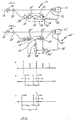
- Fig. 3a shows in this context possible coherent-optical transmission channels of a certain frequency, of which here, for example, the channel with the frequency f S , below which the frequency f2 of the partial beam fed by the laser 26, 26 'is shown.
- the laser 26, 26 serves over its one partial beam with the frequency f2 as a local oscillator laser, as is otherwise used as a separate component.
- the laser 26, 26 ' by means of the in the opposite direction to the signal wave f S , which arrives from the remote transmitting / receiving part, in the optical waveguide 12, 12' coupled other partial beam with the frequency f1 for signal transmission to a remote receiver, ie as a transmitting oscillator Laser.
- This other sub-beam with the frequency f 1 can be modulated in a known manner with a message in the external modulator 29, 29 '.
- the module 16, 16 ' is used in such a way that, according to the two possibilities mentioned above, the laser 26, 26' is used as the transmit oscillator laser (SO) and at the same time as the local oscillator laser (LO), it is in this configuration according to the figure 3b the frequency f2 less than the frequency f S of one transmission channel and the frequency f1 less than the frequency f i of another transmission channel.
- the fundamental frequency f0 of the radiation emitted by the laser 26, 26 ' lies between the frequencies f1 and f2 of the two partial beams.
- the frequency control of the dual-function laser module 16, 16 'in this case, via line 22, 22', which couples the receiver 13 back to the laser 26, 26 ', is carried out, for example, in heterodyne reception via an intermediate frequency control or another known method.
- the frequency f2 of the first partial beam is stabilized with respect to the frequency f S of the signal wave (or with respect to a defined reference frequency f R ).
- these frequencies f1 and f2 can be set to any frequency f i of a transmission channel of the coherent-optical transmission system, provided that these are within the modulation bandwidth of the frequency shifters 27, 28 and 27 ' , 28 'lies.
- ⁇ f B is referred to as the Brillouin frequency shift and can be 11.2 GHz, for example, at 1.5 ⁇ m light wavelength ( ⁇ f B depends on the light wavelength).
- ⁇ f B Since ⁇ f B is relatively large, it is necessary because of the RF limitation of the frequency shifters that the signs of ⁇ f FS1 and ⁇ f FS2 are chosen differently. Since the signal to be amplified is longer-wave (Stokes shift), the pump wave with the frequency f1 on the side of higher frequencies with respect to the frequency f S of the signal wave and the basic emission frequency f0 of the laser 26, 26 'must be placed.
- the module 16, 16 'simultaneously for all three modes of operation mentioned above, that is to say both as a transmitting oscillator laser and as a local oscillator laser and also as a fiber Brillouin amplifier.
- This can be done, for example, in such a way that the partial beam with the frequency f 1 is divided again with the aid of a beam splitter.
- the partial beam with the frequency f 1 is preferably used alternately for transmitting a signal wave with the frequency f 1 or for optical amplification of the signal wave coming from the remote transmitting / receiving part with the frequency f S. This results in a triple functional laser module 16, 16 '.
- At least some of the components of the transmitting / receiving part 11, 11 ' can be in hybrid form and can be linked to one another via optical waveguides.
Landscapes
- Physics & Mathematics (AREA)
- Electromagnetism (AREA)
- Engineering & Computer Science (AREA)
- Computer Networks & Wireless Communication (AREA)
- Signal Processing (AREA)
- Optical Communication System (AREA)
- Small-Scale Networks (AREA)
- Glass Compositions (AREA)
- Telephone Function (AREA)
- Optical Fibers, Optical Fiber Cores, And Optical Fiber Bundles (AREA)
Claims (11)
- Ensemble émetteur-récepteur pour un système de transmission optique bidirectionnel à ondes cohérentes, contenant comme instrument de transmission un guide d'ondes lumineuses, comportant un laser pour émettre une onde porteuse du signal et un modulateur, comportant un récepteur optique à superposition d'ondes cohérentes, et un démodulateur, le laser étant employé également pour émettre un faisceau oscillatoire pour le récepteur optique à superposition d'ondes cohérentes du même ensemble émetteur-récepteur,
caractérisé,
par le fait qu'il comporte un premier coupleur (19, 19′) pour coupler, dans le récepteur optique à superposition d'ondes cohérentes (13, 13′), un premier faisceau partiel du laser (26, 26′) en direction de l'onde porteuse du signal qui arrive d'un ensemble émetteur-récepteur éloigné et un second coupleur (20̸, 20̸′) pour coupler, dans le guide d'ondes lumineuses (12, 12′), un second faisceau partiel du laser (26, 26′) en direction opposée à celle de l'onde porteuse du signal qui arrive de l'ensemble émetteur-récepteur éloigné. - Ensemble émetteur-récepteur selon la revendication 1, caractérisé par le fait que le laser (26, 26′) est simultanément employé pour l'amplification optique de l'onde porteuse du signal qui arrive de l'ensemble émetteur-récepteur éloigné (11, 11′) par l'intermédiaire du guide d'ondes lumineuses (12, 12′).
- Ensemble émetteur-récepteur selon la revendication 1 ou 2, caractérisé par le fait que le laser (26′) est un laser à émission unidirectionnelle dont le faisceau peut se diviser en au moins deux faisceaux partiels.
- Ensemble émetteur-récepteur selon l'une des revendications précédentes, caractérisé par le fait que sur le chemin du faisceau émis par le laser (26, 26′) ou de ses faisceaux partiels, est disposé au moins un composant (27, 28; 27′, 28′) décalant en fréquence.
- Ensemble émetteur-récepteur selon l'une des revendications 2 à 4, caractérisé par le fait que du second faisceau partiel du laser (26, 26′) on fait dériver un troisième faisceau partiel dont la fréquence est supérieure à celle de l'onde porteuse du signal.
- Ensemble émetteur-récepteur selon la revendication 4, caractérisé par le fait que le composant (27, 28, 27′, 28′) décalant en fréquence peut s'employer seul ou en liaison avec des composants optiques, sélectifs en fréquence, pour la modulation de l'onde porteuse du signal.
- Ensemble émetteur-récepteur selon la revendication 3, caractérisé par le fait qu'entre le laser (26′) à émission unidirectionnelle et un dispositif (31) de division du faisceau est disposé un isolateur optique (32).
- Ensemble émetteur-récepteur selon l'une des revendications 4 à 7, caractérisé par le fait que les fréquences (f₁, f₂, etc.) des faisceaux partiels, dérivées par décalage de fréquence par rapport à la fréquence de base (f₀) du faisceau émis par le laser (26, 26′) peuvent être choisies indépendantes l'une de l'autre, mais qu'elles peuvent toutefois être stabilisée en commun par une régulation de fréquence intermédiaire par rapport à un fréquence de référence.
- Ensemble émetteur-récepteur selon l'une des revendications 4 à 8, caractérisé par le fait que le second faisceau partiel est employé avec une seconde fréquence (f₁) pour l'émission de signaux optiques sur la seconde fréquence (f₁) et que le premier faisceau partiel est employé avec une première fréquence (f₂) pour la réception optique, par superposition d'ondes cohérentes, de l'onde porteuse du signal.
- Ensemble émetteur-récepteur selon l'une des revendications 4 à 8, caractérisé par le fait que le second faisceau partiel est employé avec une seconde fréquence (f₁) pour l'amplification optique et que le premier faisceau partiel est employé avec une première fréquence (f₂) pour la réception optique, par superposition d'ondes cohérentes, de l'onde porteuse du signal.
- Ensemble émetteur-récepteur selon la revendication 10, caractérisé par le fait que le second faisceau partiel est employé avec la seconde fréquence (f₁) alternativement pour émettre une onde porteuse du signal à la seconde fréquence (f₁) et pour l'amplification optique de l'onde porteuse du signal envoyée en direction opposée.
Applications Claiming Priority (2)
| Application Number | Priority Date | Filing Date | Title |
|---|---|---|---|
| DE3827228 | 1988-08-11 | ||
| DE3827228A DE3827228A1 (de) | 1988-08-11 | 1988-08-11 | Sende/empfangsteil fuer ein bidirektionales kohaerent-optisches uebertragungssystem |
Publications (3)
| Publication Number | Publication Date |
|---|---|
| EP0354567A2 EP0354567A2 (fr) | 1990-02-14 |
| EP0354567A3 EP0354567A3 (fr) | 1991-09-18 |
| EP0354567B1 true EP0354567B1 (fr) | 1994-12-14 |
Family
ID=6360624
Family Applications (1)
| Application Number | Title | Priority Date | Filing Date |
|---|---|---|---|
| EP89114799A Expired - Lifetime EP0354567B1 (fr) | 1988-08-11 | 1989-08-10 | Ensemble émission-réception pour un système de communication bidirectionnel cohérent et optique |
Country Status (8)
| Country | Link |
|---|---|
| US (1) | US5121241A (fr) |
| EP (1) | EP0354567B1 (fr) |
| JP (1) | JP2718770B2 (fr) |
| AT (1) | ATE115797T1 (fr) |
| AU (1) | AU618388B2 (fr) |
| CA (1) | CA1306287C (fr) |
| DE (2) | DE3827228A1 (fr) |
| ES (1) | ES2068220T3 (fr) |
Families Citing this family (30)
| Publication number | Priority date | Publication date | Assignee | Title |
|---|---|---|---|---|
| US5267074A (en) * | 1990-01-22 | 1993-11-30 | U.S. Philips Corporation | Coherent optical heterodyne transmission system |
| DE4005517A1 (de) * | 1990-02-22 | 1991-09-05 | Sensys Ag | Vorrichtung zu wellenleiterlosen bidirektionalen licht- oder infrarotuebertragung von tondarbietungen, digitalen signalen, messwerten oder bewegten fernsehbildern |
| US5384573A (en) * | 1990-10-29 | 1995-01-24 | Essex Corporation | Image synthesis using time sequential holography |
| DE4036327A1 (de) * | 1990-11-15 | 1992-05-21 | Standard Elektrik Lorenz Ag | Optisches nachrichtenuebertragungssystem mit einem faseroptischen verstaerker |
| DE69131092T2 (de) * | 1990-12-06 | 1999-08-12 | Nec Corp., Tokio/Tokyo | Verfahren zum Senden und Empfangen von kohärenten Lichtsignalen |
| EP0523780A3 (en) * | 1991-07-15 | 1993-03-03 | N.V. Philips' Gloeilampenfabrieken | Coherent optical telecommunication network |
| JP3425964B2 (ja) * | 1992-03-19 | 2003-07-14 | 富士通株式会社 | 誘導ブリルアン散乱を用いた光信号生成装置及び光伝送システム |
| US5359450A (en) * | 1992-06-25 | 1994-10-25 | Synchronous Communications, Inc. | Optical transmission system |
| EP0609620B1 (fr) * | 1993-01-30 | 1999-02-10 | The BOC Group plc | Séparation de gaz |
| GB9306136D0 (en) * | 1993-03-24 | 1993-05-12 | Plessey Telecomm | Opto-electronic circuits |
| GB9315431D0 (en) * | 1993-07-26 | 1993-09-08 | Plessey Telecomm | Optical communication system |
| US5526158A (en) * | 1994-12-22 | 1996-06-11 | Trw Inc. | Low-bias heterodyne fiber-optic communication link |
| US5541759A (en) * | 1995-05-09 | 1996-07-30 | Microsym Computers, Inc. | Single fiber transceiver and network |
| US5847853A (en) * | 1995-12-29 | 1998-12-08 | Micron Technology, Inc. | Modulation and demodulation of light to facilitate transmission of information |
| US6011615A (en) * | 1997-06-09 | 2000-01-04 | Lucent Technologies Inc. | Fiber optic cable having a specified path average dispersion |
| US6118396A (en) * | 1997-12-24 | 2000-09-12 | Massachusetts Institute Of Technology | Optically sampling, demultiplexing, and A/D converting system with improved speed |
| DE10046941A1 (de) * | 2000-09-21 | 2002-04-25 | Siemens Ag | Verfahren und Anordnung zur Verbesserung der Signalqualität eines modulierten optischen Übertragungssignals |
| WO2003032530A1 (fr) * | 2001-10-11 | 2003-04-17 | Axonlink (Bvi) Corporation | Appareil et systeme de communication optique |
| KR100450748B1 (ko) * | 2001-12-27 | 2004-10-01 | 한국전자통신연구원 | 유도 브릴루앙 증폭을 이용한 양방향 광 전송 장치 및 방법 |
| EP1453234A3 (fr) * | 2003-02-27 | 2006-05-17 | ECI Telecom Ltd. | Système et procédé de communication optique |
| US7209664B1 (en) * | 2003-06-10 | 2007-04-24 | Nortel Networks Limited | Frequency agile transmitter and receiver architecture for DWDM systems |
| US7269356B2 (en) * | 2003-07-09 | 2007-09-11 | Lucent Technologies Inc. | Optical device with tunable coherent receiver |
| US8032032B2 (en) | 2008-11-14 | 2011-10-04 | Bae Systems Information And Electronic Systems Integration Inc. | Bi-directional optical link between multiple data sources and a processing node in an avionics platform |
| JP5636684B2 (ja) * | 2010-01-29 | 2014-12-10 | 富士通株式会社 | コヒーレント光通信装置及びコヒーレント光通信方法 |
| US8548333B2 (en) | 2010-04-02 | 2013-10-01 | Infinera Corporation | Transceiver photonic integrated circuit |
| US9369321B2 (en) * | 2011-09-22 | 2016-06-14 | Northrop Grumman Systems Corporation | Increasing sensor data carrying capability of phase generated carriers |
| US9584220B2 (en) | 2013-03-15 | 2017-02-28 | Nec Corporation | Optical transmission/reception device, optical communication system and optical transmission/reception method |
| US9859678B2 (en) | 2014-09-23 | 2018-01-02 | Harris Corporation | Communications device with optical injection locking source and related methods |
| US20180188456A1 (en) | 2015-07-09 | 2018-07-05 | Nec Corporation | Pluggable optical module and optical communication system |
| CN105896309A (zh) * | 2016-06-13 | 2016-08-24 | 深圳新飞通光电子技术有限公司 | 双向输出的dfb可调谐激光模块及其相干光传输系统 |
Family Cites Families (13)
| Publication number | Priority date | Publication date | Assignee | Title |
|---|---|---|---|---|
| US470474A (en) * | 1892-03-08 | collet | ||
| US3916412A (en) * | 1974-08-29 | 1975-10-28 | United Technologies Corp | Frequency stabilized single oscillator transceivers |
| US4420841A (en) * | 1981-05-29 | 1983-12-13 | Westinghouse Electric Corp. | Optically coupled bidirectional transceiver |
| JPS5884550A (ja) * | 1981-11-16 | 1983-05-20 | Nec Corp | 光フアイバ双方向伝送システム |
| JPS59208952A (ja) * | 1983-05-12 | 1984-11-27 | Fujitsu Ltd | 双方向コヒ−レント光通信方式 |
| CA1236883A (fr) * | 1984-07-02 | 1988-05-17 | Neal S. Bergano | Systeme de communication par ondes lumineuses utilisant la detection homodyne |
| JPS61212931A (ja) * | 1985-03-18 | 1986-09-20 | Nec Corp | 位相偏移変調光送信装置 |
| JPH0833564B2 (ja) * | 1985-05-09 | 1996-03-29 | ブリティシュ・テレコミュニケ−ションズ・パブリック・リミテッド・カンパニ | 光ホモダイン検波方法および装置 |
| CA1235185A (fr) * | 1985-06-12 | 1988-04-12 | Northern Telecom Limited | Ligne de service a fibres optiques |
| JPS62114340A (ja) * | 1985-11-13 | 1987-05-26 | Nec Corp | 双方向光通信装置 |
| JPH0681103B2 (ja) * | 1986-08-28 | 1994-10-12 | 富士通株式会社 | コヒーレント光通信用送受信器 |
| JPS63245143A (ja) * | 1987-03-31 | 1988-10-12 | Fujitsu Ltd | 光通信方式 |
| DE3713340A1 (de) * | 1987-04-21 | 1988-11-10 | Deutsche Bundespost | Verfahren zur optischen nachrichtenuebertragung |
-
1988
- 1988-08-11 DE DE3827228A patent/DE3827228A1/de not_active Withdrawn
-
1989
- 1989-08-09 AU AU39456/89A patent/AU618388B2/en not_active Ceased
- 1989-08-09 CA CA000607820A patent/CA1306287C/fr not_active Expired - Lifetime
- 1989-08-09 JP JP1206602A patent/JP2718770B2/ja not_active Expired - Fee Related
- 1989-08-10 AT AT89114799T patent/ATE115797T1/de not_active IP Right Cessation
- 1989-08-10 EP EP89114799A patent/EP0354567B1/fr not_active Expired - Lifetime
- 1989-08-10 US US07/392,087 patent/US5121241A/en not_active Expired - Lifetime
- 1989-08-10 DE DE58908763T patent/DE58908763D1/de not_active Expired - Fee Related
- 1989-08-10 ES ES89114799T patent/ES2068220T3/es not_active Expired - Lifetime
Also Published As
| Publication number | Publication date |
|---|---|
| ATE115797T1 (de) | 1994-12-15 |
| EP0354567A3 (fr) | 1991-09-18 |
| DE3827228A1 (de) | 1990-02-15 |
| EP0354567A2 (fr) | 1990-02-14 |
| JP2718770B2 (ja) | 1998-02-25 |
| ES2068220T3 (es) | 1995-04-16 |
| US5121241A (en) | 1992-06-09 |
| JPH02256334A (ja) | 1990-10-17 |
| AU3945689A (en) | 1990-02-15 |
| AU618388B2 (en) | 1991-12-19 |
| DE58908763D1 (de) | 1995-01-26 |
| CA1306287C (fr) | 1992-08-11 |
Similar Documents
| Publication | Publication Date | Title |
|---|---|---|
| EP0354567B1 (fr) | Ensemble émission-réception pour un système de communication bidirectionnel cohérent et optique | |
| DE69127568T2 (de) | Telemetrie für optischen Faserzwischenverstärker | |
| EP1776785B1 (fr) | Dispositif pour generer et moduler un signal haute frequence | |
| DE3782556T2 (de) | Lichtuebertragungssystem. | |
| DE69011718T2 (de) | Optischer Regenerator und seine Verwendung in einem optischen Netzwerk. | |
| DE69013662T2 (de) | Schmalbandige Laserquelle. | |
| DE3232430C2 (de) | Optisches Nachrichtenübertragungssystem | |
| DE69426426T2 (de) | Optisches bidirektionales Kommunikationssystem mit Wellenlängenmultiplex | |
| DE3689587T2 (de) | Optisches Übertragungssystem und -verfahren mit kohärenter Detektion. | |
| DE69631817T2 (de) | Sender für modulierte und depolarisierte optische Signale | |
| DE69833913T2 (de) | Unterdrückung des kohärenten Rayleighrauschens in bidirektionalen Übertragungssystemen | |
| EP0461380A2 (fr) | Système de transmission de données radio, notamment système de radio mobile cellulaire | |
| DE69632720T2 (de) | Mehrfrequenzphasenmodulation für lichtwellenübertragungssystem | |
| DE4415176A1 (de) | Vorrichtung und Verfahren zur Dispersionskompensation in einem faseroptischen Übertragungssystem | |
| EP0238134B1 (fr) | Réflectomètre à domaines optiques dans le temps avec réception-hétérodyn | |
| DE4430821A1 (de) | Optische Kommunikationsvorrichtung | |
| DE3637809A1 (de) | Sender fuer kohaerente lichtwellen | |
| DE69429418T2 (de) | Rein optischer Inverter | |
| DE69801709T2 (de) | Optisches Übertragungssystem mit dynamischer Kompensation der übertragenen Leistung | |
| DE69313287T2 (de) | Optische quelle für ein kommunikationssystem | |
| DE3871604T2 (de) | Sender und senderempfaenger fuer ein kohaerentes optisches system. | |
| EP0349766A2 (fr) | Système de transmission d'informations optique, concernant en particulier le raccordement d'abonnés | |
| EP0485813B1 (fr) | Système de télécommunications optique avec amplificateur en fibre optique | |
| DE69720450T2 (de) | Optische Dispersionskompensation | |
| DE69512032T2 (de) | Optische zeitbereichreflektometrie |
Legal Events
| Date | Code | Title | Description |
|---|---|---|---|
| PUAI | Public reference made under article 153(3) epc to a published international application that has entered the european phase |
Free format text: ORIGINAL CODE: 0009012 |
|
| AK | Designated contracting states |
Kind code of ref document: A2 Designated state(s): AT BE CH DE ES FR GB IT LI NL SE |
|
| PUAL | Search report despatched |
Free format text: ORIGINAL CODE: 0009013 |
|
| AK | Designated contracting states |
Kind code of ref document: A3 Designated state(s): AT BE CH DE ES FR GB IT LI NL SE |
|
| 17P | Request for examination filed |
Effective date: 19911018 |
|
| RAP3 | Party data changed (applicant data changed or rights of an application transferred) |
Owner name: ALCATEL N.V. Owner name: ALCATEL SEL AKTIENGESELLSCHAFT |
|
| 17Q | First examination report despatched |
Effective date: 19940126 |
|
| GRAA | (expected) grant |
Free format text: ORIGINAL CODE: 0009210 |
|
| AK | Designated contracting states |
Kind code of ref document: B1 Designated state(s): AT BE CH DE ES FR GB IT LI NL SE |
|
| REF | Corresponds to: |
Ref document number: 115797 Country of ref document: AT Date of ref document: 19941215 Kind code of ref document: T |
|
| ITF | It: translation for a ep patent filed | ||
| REF | Corresponds to: |
Ref document number: 58908763 Country of ref document: DE Date of ref document: 19950126 |
|
| EAL | Se: european patent in force in sweden |
Ref document number: 89114799.3 |
|
| GBT | Gb: translation of ep patent filed (gb section 77(6)(a)/1977) |
Effective date: 19950109 |
|
| ET | Fr: translation filed | ||
| REG | Reference to a national code |
Ref country code: ES Ref legal event code: FG2A Ref document number: 2068220 Country of ref document: ES Kind code of ref document: T3 |
|
| PLBE | No opposition filed within time limit |
Free format text: ORIGINAL CODE: 0009261 |
|
| STAA | Information on the status of an ep patent application or granted ep patent |
Free format text: STATUS: NO OPPOSITION FILED WITHIN TIME LIMIT |
|
| 26N | No opposition filed | ||
| PGFP | Annual fee paid to national office [announced via postgrant information from national office to epo] |
Ref country code: CH Payment date: 20010716 Year of fee payment: 13 |
|
| PGFP | Annual fee paid to national office [announced via postgrant information from national office to epo] |
Ref country code: NL Payment date: 20010724 Year of fee payment: 13 |
|
| PGFP | Annual fee paid to national office [announced via postgrant information from national office to epo] |
Ref country code: AT Payment date: 20010725 Year of fee payment: 13 |
|
| PGFP | Annual fee paid to national office [announced via postgrant information from national office to epo] |
Ref country code: SE Payment date: 20010802 Year of fee payment: 13 |
|
| PGFP | Annual fee paid to national office [announced via postgrant information from national office to epo] |
Ref country code: BE Payment date: 20010810 Year of fee payment: 13 |
|
| REG | Reference to a national code |
Ref country code: GB Ref legal event code: IF02 |
|
| PG25 | Lapsed in a contracting state [announced via postgrant information from national office to epo] |
Ref country code: AT Free format text: LAPSE BECAUSE OF NON-PAYMENT OF DUE FEES Effective date: 20020810 |
|
| PG25 | Lapsed in a contracting state [announced via postgrant information from national office to epo] |
Ref country code: SE Free format text: LAPSE BECAUSE OF NON-PAYMENT OF DUE FEES Effective date: 20020811 |
|
| PG25 | Lapsed in a contracting state [announced via postgrant information from national office to epo] |
Ref country code: LI Free format text: LAPSE BECAUSE OF NON-PAYMENT OF DUE FEES Effective date: 20020831 Ref country code: CH Free format text: LAPSE BECAUSE OF NON-PAYMENT OF DUE FEES Effective date: 20020831 Ref country code: BE Free format text: LAPSE BECAUSE OF NON-PAYMENT OF DUE FEES Effective date: 20020831 |
|
| BERE | Be: lapsed |
Owner name: *ALCATEL N.V. Effective date: 20020831 |
|
| PG25 | Lapsed in a contracting state [announced via postgrant information from national office to epo] |
Ref country code: NL Free format text: LAPSE BECAUSE OF NON-PAYMENT OF DUE FEES Effective date: 20030301 |
|
| EUG | Se: european patent has lapsed | ||
| REG | Reference to a national code |
Ref country code: CH Ref legal event code: PL |
|
| NLV4 | Nl: lapsed or anulled due to non-payment of the annual fee |
Effective date: 20030301 |
|
| PGFP | Annual fee paid to national office [announced via postgrant information from national office to epo] |
Ref country code: GB Payment date: 20030728 Year of fee payment: 15 |
|
| PGFP | Annual fee paid to national office [announced via postgrant information from national office to epo] |
Ref country code: DE Payment date: 20030805 Year of fee payment: 15 |
|
| PGFP | Annual fee paid to national office [announced via postgrant information from national office to epo] |
Ref country code: ES Payment date: 20030807 Year of fee payment: 15 |
|
| PGFP | Annual fee paid to national office [announced via postgrant information from national office to epo] |
Ref country code: FR Payment date: 20030813 Year of fee payment: 15 |
|
| PG25 | Lapsed in a contracting state [announced via postgrant information from national office to epo] |
Ref country code: GB Free format text: LAPSE BECAUSE OF NON-PAYMENT OF DUE FEES Effective date: 20040810 |
|
| PG25 | Lapsed in a contracting state [announced via postgrant information from national office to epo] |
Ref country code: ES Free format text: LAPSE BECAUSE OF NON-PAYMENT OF DUE FEES Effective date: 20040811 |
|
| PG25 | Lapsed in a contracting state [announced via postgrant information from national office to epo] |
Ref country code: DE Free format text: LAPSE BECAUSE OF NON-PAYMENT OF DUE FEES Effective date: 20050301 |
|
| GBPC | Gb: european patent ceased through non-payment of renewal fee |
Effective date: 20040810 |
|
| PG25 | Lapsed in a contracting state [announced via postgrant information from national office to epo] |
Ref country code: FR Free format text: LAPSE BECAUSE OF NON-PAYMENT OF DUE FEES Effective date: 20050429 |
|
| REG | Reference to a national code |
Ref country code: FR Ref legal event code: ST |
|
| PG25 | Lapsed in a contracting state [announced via postgrant information from national office to epo] |
Ref country code: IT Free format text: LAPSE BECAUSE OF NON-PAYMENT OF DUE FEES;WARNING: LAPSES OF ITALIAN PATENTS WITH EFFECTIVE DATE BEFORE 2007 MAY HAVE OCCURRED AT ANY TIME BEFORE 2007. THE CORRECT EFFECTIVE DATE MAY BE DIFFERENT FROM THE ONE RECORDED. Effective date: 20050810 |
|
| REG | Reference to a national code |
Ref country code: ES Ref legal event code: FD2A Effective date: 20040811 |