EP0874949B1 - Schwenkkolbenmaschine - Google Patents
Schwenkkolbenmaschine Download PDFInfo
- Publication number
- EP0874949B1 EP0874949B1 EP97943899A EP97943899A EP0874949B1 EP 0874949 B1 EP0874949 B1 EP 0874949B1 EP 97943899 A EP97943899 A EP 97943899A EP 97943899 A EP97943899 A EP 97943899A EP 0874949 B1 EP0874949 B1 EP 0874949B1
- Authority
- EP
- European Patent Office
- Prior art keywords
- oscillating
- pistons
- piston engine
- housing
- piston
- Prior art date
- Legal status (The legal status is an assumption and is not a legal conclusion. Google has not performed a legal analysis and makes no representation as to the accuracy of the status listed.)
- Expired - Lifetime
Links
- 238000007789 sealing Methods 0.000 claims description 17
- 239000000446 fuel Substances 0.000 claims description 11
- 238000005096 rolling process Methods 0.000 claims description 6
- 238000002347 injection Methods 0.000 claims description 4
- 239000007924 injection Substances 0.000 claims description 4
- 230000000717 retained effect Effects 0.000 claims 1
- 239000000203 mixture Substances 0.000 description 18
- 239000011324 bead Substances 0.000 description 11
- 238000002485 combustion reaction Methods 0.000 description 6
- 230000000295 complement effect Effects 0.000 description 2
- 230000001419 dependent effect Effects 0.000 description 2
- 230000000694 effects Effects 0.000 description 2
- 238000010276 construction Methods 0.000 description 1
- 230000003292 diminished effect Effects 0.000 description 1
- 230000009191 jumping Effects 0.000 description 1
- 239000010687 lubricating oil Substances 0.000 description 1
- 238000005461 lubrication Methods 0.000 description 1
- 230000001404 mediated effect Effects 0.000 description 1
- 239000010705 motor oil Substances 0.000 description 1
- 238000004091 panning Methods 0.000 description 1
- 230000002093 peripheral effect Effects 0.000 description 1
- 230000001105 regulatory effect Effects 0.000 description 1
- 230000029058 respiratory gaseous exchange Effects 0.000 description 1
- 230000007704 transition Effects 0.000 description 1
Images







Classifications
-
- F—MECHANICAL ENGINEERING; LIGHTING; HEATING; WEAPONS; BLASTING
- F01—MACHINES OR ENGINES IN GENERAL; ENGINE PLANTS IN GENERAL; STEAM ENGINES
- F01C—ROTARY-PISTON OR OSCILLATING-PISTON MACHINES OR ENGINES
- F01C1/00—Rotary-piston machines or engines
- F01C1/30—Rotary-piston machines or engines having the characteristics covered by two or more groups F01C1/02, F01C1/08, F01C1/22, F01C1/24 or having the characteristics covered by one of these groups together with some other type of movement between co-operating members
- F01C1/40—Rotary-piston machines or engines having the characteristics covered by two or more groups F01C1/02, F01C1/08, F01C1/22, F01C1/24 or having the characteristics covered by one of these groups together with some other type of movement between co-operating members having the movement defined in group F01C1/08 or F01C1/22 and having a hinged member
- F01C1/44—Rotary-piston machines or engines having the characteristics covered by two or more groups F01C1/02, F01C1/08, F01C1/22, F01C1/24 or having the characteristics covered by one of these groups together with some other type of movement between co-operating members having the movement defined in group F01C1/08 or F01C1/22 and having a hinged member with vanes hinged to the inner member
-
- F—MECHANICAL ENGINEERING; LIGHTING; HEATING; WEAPONS; BLASTING
- F02—COMBUSTION ENGINES; HOT-GAS OR COMBUSTION-PRODUCT ENGINE PLANTS
- F02B—INTERNAL-COMBUSTION PISTON ENGINES; COMBUSTION ENGINES IN GENERAL
- F02B75/00—Other engines
- F02B75/02—Engines characterised by their cycles, e.g. six-stroke
- F02B2075/022—Engines characterised by their cycles, e.g. six-stroke having less than six strokes per cycle
- F02B2075/027—Engines characterised by their cycles, e.g. six-stroke having less than six strokes per cycle four
-
- F—MECHANICAL ENGINEERING; LIGHTING; HEATING; WEAPONS; BLASTING
- F02—COMBUSTION ENGINES; HOT-GAS OR COMBUSTION-PRODUCT ENGINE PLANTS
- F02B—INTERNAL-COMBUSTION PISTON ENGINES; COMBUSTION ENGINES IN GENERAL
- F02B75/00—Other engines
- F02B75/12—Other methods of operation
- F02B2075/125—Direct injection in the combustion chamber for spark ignition engines, i.e. not in pre-combustion chamber
-
- Y—GENERAL TAGGING OF NEW TECHNOLOGICAL DEVELOPMENTS; GENERAL TAGGING OF CROSS-SECTIONAL TECHNOLOGIES SPANNING OVER SEVERAL SECTIONS OF THE IPC; TECHNICAL SUBJECTS COVERED BY FORMER USPC CROSS-REFERENCE ART COLLECTIONS [XRACs] AND DIGESTS
- Y02—TECHNOLOGIES OR APPLICATIONS FOR MITIGATION OR ADAPTATION AGAINST CLIMATE CHANGE
- Y02T—CLIMATE CHANGE MITIGATION TECHNOLOGIES RELATED TO TRANSPORTATION
- Y02T10/00—Road transport of goods or passengers
- Y02T10/10—Internal combustion engine [ICE] based vehicles
- Y02T10/12—Improving ICE efficiencies
Definitions
- the invention relates to a swing piston machine, with a Housing with a circular inner wall, in which several than two-armed lever trained pistons, two of which are each adjacent pistons are in meshing engagement with one another one piston axis parallel to a central housing axis arranged pivotably and together in one direction of rotation are movable, the piston axes on one to Inner wall of the housing concentric circular path around the Rotate the housing axis.
- Such a swing piston machine is from WO 93/01395 known.
- Swing piston machines belong to a genus of internal combustion engines, in which the individual work cycles of admission, Compressing, igniting, expanding and expelling the combustion mixture by rocker-like swivel movements of the individual Pistons are mediated between two end positions.
- the Swiveling movement of the pistons is via corresponding intermediate links converted into a rotary motion of an output shaft.
- the pistons are stationary in the embodiment Housing arranged and only lead back and forth swiveling movements between two end positions.
- About the swivel movements in rotary movements one arranged centrally in the housing is the output shaft with in with respect to these eccentric, diametrically opposed Curve links connected rigidly on which Roll the surfaces of the pistons facing the output shaft.
- These piston surfaces facing the output shaft are shown in defined parabolic, while the curve followers are designed circular cylindrical.
- the pistons are not only pivotable stored in the housing but they are also in a direction of rotation around the central housing axis.
- each of the curve sequence members has a fixed one with it connected pinion on which meshes with an idler gear stands, which in turn meshes with a central gear, which is attached to the output shaft.
- the curve followers not only have the function that To control swiveling movements of the individual pistons, but also the total driving force of the pistons towards the output shaft transfer. Accordingly, the bearings of the cam followers be very stable.
- the function-related drop-shaped profile is the Curve links disadvantageous in that it is relatively pointed feeds so that when the pistons rotate, when the pistons over the tip of the curve followers run, a "hard” transition between gently curved and strongly curved rolling areas when passing on. This contributes to a decrease in This swing piston machine runs smoothly.
- From DE-OS 15 51 101 is a centrifugal piston internal combustion engine known, the six spaced pistons of about has triangular shape, which is so on a circular Drive wheel are pivotally mounted so that they rotate in the housing of the motor due to the centrifugal forces that occur be pressed against the inner wall of the housing.
- the pistons are independent of each other along the inner wall guided.
- To achieve the breathing movements of the pistons is the inner wall of the housing approximately oval or trochoidal.
- a rotary piston engine is known from GB-PS 14 70 648, arranged with a total of four pistons in the motor housing are, each of which two diametrically opposite pistons form a pair of pistons.
- the inside wall of the housing is approximately elliptical formed, the pistons rotating in the housing also as in the aforementioned known centrifugal piston internal combustion engine are guided along the inner wall to to achieve the work cycles of the engine. Neighboring pistons are each connected in such a way that the connection points each form a seal, always on the inner wall is present.
- the inner wall has elliptically-shaped fixed curve followers arranged on which rollers attached to the piston run to the pistons against the inner wall of the housing to press.
- cam follower for each pair of pistons provided, the two curve sequence members being different are designed.
- the invention is therefore based on the object of a swing piston machine of the type mentioned at the outset, that the disadvantages of the prior art are avoided be that in particular the technical effort of the swing piston machine reduced and at the same time increased smoothness and the torque is high even at low speeds.
- the invention thus frees itself from the concept of of which in the prior art according to the Known swing piston machines WO 93/01395 provided two were to be arranged eccentrically to the housing axis and movable to design. Instead, according to the invention, a housing-fixed, centrally arranged curve piece provided, whereby the Effort of the swing piston machine according to the invention essential is reduced because there are far fewer moving parts in the Housing are provided. This in turn advantageously contributes to this in that the smooth running of the swivel piston engine according to the invention is increased.
- the outer contour corresponds of the curve section exactly that of one of the housing axes on the next lying point of the tread curve described, which results from the overlay from the swivel and Orbital movement of the pistons results in a full revolution.
- This measure has the advantage that the pistons along the Outer contour of the curve piece are guided such that the Piston under constant contact during a full revolution of the treads with the outer contour of the curve piece around Run around the curve section and do so in accordance with the working cycles Carry out swiveling movements without being on the Piston forces act, which impair the Operational safety could drive. In other words, it is Outer contour resulting from the swiveling and rotating movements resulting "natural" trajectory adjusted. Likewise, the Smooth running of the oscillating piston machine according to the invention further elevated.
- this extends Axial curve piece over approximately the entire length of the housing, however, the running surfaces of the pistons and the outer contour touch the curve piece only in axially limited areas.
- This measure has the advantage that the exact management of the Piston is guaranteed along the central curve piece and at the same time friction losses on the contacting treads the piston and the curve piece can be reduced.
- Lower friction losses have the advantage that the efficiency the oscillating piston machine according to the invention is increased, and that the wear of the treads and the outer contour of the Curve piece is reduced.
- pistons act as two-armed levers are formed and the treads at one end of one of the two lever arms of the pistons are arranged.
- this measure has the advantage that when the piston rotates around the curve piece, the pivoting movement the piston around its respective piston axis from the am End of the lever arms arranged treads with the largest possible Torque is supported.
- This arrangement of the treads on the piston thus enables a well-defined Guidance and control of the pistons.
- the treads are the piston surfaces of rotatably attached to the piston Rollers.
- This measure has the advantage that the rollers on the Roll the outer contour of the curve piece, causing friction losses between the running surfaces of the pistons and the outer contour of the Are further reduced. This makes a less Lubrication of the contact surfaces between the running surfaces of the pistons and the outer contour of the curve piece required and the Wear on the surfaces that run against one another is reduced.
- rollers have a half diameter have less than the radius of curvature of concave Sections of the curve piece is.
- This measure has the advantage that the piston in every position a substantially linear contact between the Running surfaces of the pistons and the outer contour of the curve piece is achieved.
- a linear contact has the advantage that the running surfaces of the pistons gently and without jumping points defined on the outer contour of the curve piece during the Run around the pistons.
- This measure has the advantage that the number of moving Share further in the swing piston engine according to the invention is reduced.
- treads at least in the areas that match the outer contour of the curve section Stand in touch are part-circular.
- the pistons are each on an axially extending axis rod mounted, the Axle bars together at the ends, each with one in the direction of rotation movable ring body are connected.
- At least one of the ring bodies is one Has external toothing with a corresponding external toothing one running parallel to the housing axis and comes eccentrically to this arranged output shaft.
- the pistons are on their axial ends axially outward through a seal sealed, the several axially protruding inwards Has sealing beads that lie sealingly against the piston.
- the curve piece around the housing axis to change the ignition timing rotatable and lockable in a rotated position is
- This embodiment has the particular advantage in that the ignition timing by the rotatability of the curve piece the oscillating piston machine according to the invention varies can be.
- This changes the ignition timing causes the curve piece from its basic position in or is turned counterclockwise, causing the top Dead center (TDC) clockwise or counterclockwise relative shifted to the fixed spark plug (s) so that a Ignition of the fuel-air mixture before or after reaching it the dead center corresponds to a late or early ignition.
- TDC top Dead center
- s fixed spark plug
- the Changing the ignition timing causes that the Spark plugs slightly earlier via an electronic control or controlled later, in other words the Change in the ignition timing by a change over time the emission of the ignition spark regulated.
- the inventive Swing piston engine is done by a mechanical Changing the position of top dead center causes the Emission of the ignition spark can remain unchanged in time.
- This measure has the advantage that the curve piece adjusted clockwise or counterclockwise can be, so that the ignition timing of the invention Swing piston machine can be varied.
- the curve piece is depending on the speed of the oscillating piston machine rotatable.
- an adjustment mechanism provided that has a worm gear.
- a worm gear provides a mechanically simple drive for the curve piece, with the additional advantage achieved is that with the worm gear a very fine stepless Rotation of the curve piece is made possible.
- the adjustment mechanism is in a further preferred embodiment electronically depending on the speed of the Swing piston machine controlled.
- the Speed of the oscillating piston machine for example, mechanically recorded be, whereby a signal is generated, which is for the control of the Adjustment mechanism is used.
- the Swing piston machine several circumferentially spaced Spark plugs, each depending on the speed of the Swing piston machine differently for generating an ignition spark can be controlled.
- This embodiment differs from that previously described embodiment, the ignition timing is adjusted, that the plurality are circumferentially spaced apart Spark plugs are controlled differently while the curve piece maintains its position.
- This configuration is therefore technically simpler, but not stepless Adjustability of the ignition timing is possible. It exists only the possibility of an early, normal or late ignition to effect without the early or late ignition gradually graded can be.
- the oscillating piston machine has a fuel injector in the direction of rotation the piston at a circumferential angle of about 25 ° before Ignition timing is arranged.
- the Swing piston machine As an alternative to the configuration of the Swing piston machine according to the invention with an eccentric arranged output shaft, it is further preferred if the Swing piston machine a concentric to the housing axis Output shaft has.
- a concentric arrangement of the output shaft has opposite an eccentric arrangement the advantage that the swing piston machine can be formed radially narrower.
- first ring body on a Has the output shaft centrally and on the outside opposite side over the axle rods with the second Ring body is firmly connected.
- the curve piece in the first ring body which has the output shaft, engages and is held by this housing.
- This measure has the advantage that the curve piece with respect of the housing is fixed, but without directly with the housing to be connected.
- the ring bodies form and the axle rods a cylindrical unit with one axially constant outer diameter.
- This constructive measure has the advantage that the from the Ring bodies, the axis rods and the curve piece formed Unit as a whole pulled out of the housing and also as Whole can be inserted because of this configuration enables the inner wall of the housing with regard to its inner diameter axially continuous homogeneous.
- This has the Advantage that the oscillating piston machine according to the invention is easy to maintain because the ring body, the axle rods and the curve piece outside the housing into one unit can be pre-assembled.
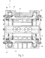
- 1 to 4 is a swing piston machine 10 in different Cuts shown.
- the oscillating piston machine 10 has a housing 12 which is made of an axially extending and substantially cylindrical central housing part 14, an axially adjoining left Housing ring flange 16 and a right housing ring flange 18 and a left housing cover 20 and a right housing cover 22 is formed (see FIG. 2).
- the left housing ring flange 16 is on the central housing part 14 by means of circumferentially distributed screws 24 and the right housing ring flange 18 on the central housing part 14 by means of the circumference distributed screws 26 attached.
- the left housing cover 20 is in turn with the left housing ring flange 16 also circumferentially distributed screws 28, and the right one Housing cover 22 is with the right housing ring flange 18 by means of screws 30 also distributed around the circumference connected.
- pistons 32, 34, 36 and 38 there are four identical pistons 32, 34, 36 and 38 in the housing 12 arranged (see. Fig. 1).
- the pistons 32, 34, 36 and 38 are in a direction of rotation 40 around a central housing axis 42 flexible, as will be explained in more detail later.
- the piston 32 is designed as a two-armed lever and has accordingly a first lever arm 44 and a second lever arm 46 on.
- the first lever arm 44 and the second lever arm 46 have radially outer surfaces 48 and 50, which have a curvature, which exactly the curvature of an inner wall 52 of correspond to the central housing part 14 so that the radial Apply outer surfaces 48 and 50 to the inner wall 52 can.
- the first lever arm 44 and the second lever arm 46 are over one radially inward curved concave section 54 rigid and connected in one piece.
- the piston 32 At the concave section 54 is the piston 32 on an axle rod 56 about a piston axis 58 pivoted so that the piston 32 between two End positions can swing back and forth, in one End position rocker-like the radially outer surface 50 and in the the other end position, as shown, the radially outer surface 48 abuts the inner wall 52.
- axle rod 56 In addition to the axle rod 56, the pistons 34, 36 and 38 are correspondingly identical axle rods 60, 62 and 64 are provided which the pistons 34, 36 and 38 just pivoted are without this having to be explained again here.
- the four axle rods 56, 60, 62 and 64 are against each other by one 90 ° offset.
- the first lever arm 44 of the piston 32 also has on it lateral end 65 on a toothing 66, the two after externally protruding, approximately semicircular teeth on average and one inward, also about in average semicircular recess is formed.
- the second lever arm 46 has one at its lateral end 67 Toothing 68 on, complementary to the toothing 66 is trained.
- the piston 32 stands with its over the toothing 66 and 68 adjacent pistons 34 and 38 in tight rolling engagement, the have corresponding complementary teeth.
- the gears roll when pivoting the pistons 32, 34, 36 and 38 into each other and at the same time have a sealing function. It can also be seen that there are always two adjacent pistons 32, 34, 36 and 38 perform opposite swiveling movements.
- Two adjacent pistons 32, 34, 36 and 38 delimit four dense workrooms 74, 76, 78 and 80, respectively Volume during operation of the oscillating piston machine 10 as a result the pivoting and orbital movement of pistons 32, 34, 36 and 38 alternately enlarged and reduced.
- the Working space 74 of the pistons 32 and 34, the axle rods 56 and 60 and a corresponding section of the inner wall 52 of the limited central housing part 14, the pistons 32, 34, 36th and 38 are also axially sealed as described later becomes.
- pistons 34, 36 and 38 have accordingly attached piston rods 78, 80 and 82.
- the piston rod 78 carries at both of its axial ends a cylindrical roller 84 and 86 (see FIG. 2), each are rotatably supported on the piston rod 78.
- the cylindrical Rollers 84 and 86 extend axially only over one Part of the length of the piston rod 78 Piston rods 74, 80 and 82 identical rollers are provided.
- the curve piece 88 has an outer contour 90 which extends in the circumferential direction alternating convex portions 92 and concave Sections 94.
- the cam piece 88 is axial End regions 96 and 98, which extends over an axial Part of the length of the curve piece 88 extend and are radially thicker than the central area of the curve piece 88.
- the axial End regions 96 and 98 form that peripheral part of the Outer contour 90 of the curve piece 88 on which the cylindrical Rollers 84 and 86 when rotating the piston 34 and the corresponding rollers of the pistons 32, 36 and 38 around the Roll the housing axis 42.
- rollers 84 and 86 accordingly form running surfaces 100 and 102 of the piston 34, respectively run along the outer contour 90 of the curve piece 88, the Treads 100 and 102 during the rotation of the piston 34 with constant contact with the outer contour 90 in the axial End areas 96 and 98 of the curve piece 88 are so that the Piston 34 continuously while rotating around the curve piece 88 to be led. The same applies to the rest Pistons 32, 36 and 38.
- a half diameter of the cylindrical rollers 84 and 86 is smaller than the area of curvature of the concave areas 94 of the axial cam piece 88.
- the outer contour of the curve piece 88 corresponds exactly to that of one closest to the housing axis 42, indicated by 104, Point of the tread 100 described trajectory, where the trajectory of point 104 is from the overlay the pivoting and orbital movement of the pistons 32, 34, 36 or 38 results in a full revolution around the housing axis 42.
- axle rods 60 and 64 (as well the axis rods 56 and 62, not visible in FIG. 3, respectively axially at the end with an annular body 106 and an annular body 108 are firmly connected, wherein the ring body 106 and 108 in the Housing 12 rotates in the direction of rotation 40 on bearing rings 110 or 112 are stored.
- the axle rods 56, 60, 62 and 64 and the Ring body 106 and 108 form a rotatable in the housing 12 Cage, with the axle rods 56, 60, 62 and 64 when rotating this cage with the pistons 32, 34, 36 and 38 with.
- axle rods 56, 60, 62 and 64 lie close together the inner wall 52 of the central housing part 14.
- the ring bodies 106 and 108 have a circumference on them arranged external toothing 120 or 122, with corresponding External teeth 124 and 126 one parallel to Housing axis 42 extending and arranged eccentrically to this Comb output shaft 126, which in a bulge 130 of the housing 12 is mounted.
- the rotation of the ring body 106 or 108 is thus in a rotational movement of the output shaft 128 transmitted.
- the output shaft 128 can, for example, with a here Gearbox of a motor vehicle, not shown be.
- the pistons 32, 34, 36 and 38 are in the axial direction one seal 132 and 134 sealed to the outside.
- the seal 132 can be seen in a plan view.
- the Seal 132 has four at right angles to each other rectilinear radially outer sections 136, 138, 140 and 142, which via connection sections 144, 146, 148 and 150 are integrally connected.
- Each of the outer sections 136, 138, 140, 142 has two axially inwardly projecting sealing beads 152 and 154, as here is exemplified for section 136 to the lateral axial ends of the pistons 32, 34, 36 and 38 sealing issue. Between the sealing beads 152 and 154 is the outer one Section 136 as well as the other sections 138, 140 and 142 recessed axially outwards.
- the connecting section 148 has a sealing bead 158 curved in accordance with the axis rod 62 on, with identical sealing beads on the connecting sections 144, 146 and 150 are provided.
- the seal 132 also has an axially outwardly extending portion 156 which embedded in corresponding recesses in the ring body 106 is (see FIG. 2).
- the seal 132 lies with the sealing beads 152 and 154 and the corresponding sealing beads of the remaining sections 138, 140 and 142 as well as with the sealing bead 158 and the Sealing beads of the other connecting sections 144, 146, 148 and 150 sealing against the pistons 32, 34, 36 and 38.
- a channel in the curve piece 88 160 is provided, which for receiving and forwarding liquid lubricants, such as motor oil, is provided can be filled through an inlet screw 162 and over additional channels 164 and 166 in the central interior of the Housing 12 pass to the treads 100 and 102 of the piston 34 and the other running surfaces of the other pistons 32, 36 and 38 and the outer contour 90 in contact therewith Lubricate curve piece 88.
- liquid lubricants such as motor oil
- the oscillating piston machine 10 has two spark plugs 168 and 170, which are embedded in the central housing part 14 are.
- a Outlet channel 174 provided in the housing 12 through which burned Mixture can be ejected. The exhaust port 174 also closes an angle with the spark plugs 168 and 170 of about 135 °.
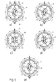
- Fig. 5a) - e) is the operation of the in 1 to 4 shown oscillating piston machine 10 as Four-stroke gasoline engine shown.
- Fig. 5a) agrees with Fig.
- the work space 78 has something downsized, so that the one already there was previously ignited fuel-air mixture by the now of the Axle rod 64 released outlet channel 166 are ejected can.
- the inlet channel 164 is in the working space 74th fresh fuel-air mixture let in, while that before fuel-air mixture let into the working space 74 now by a corresponding pivoting movement of the pistons 32 and 34 is compressed.
- the pistons 32, 34, 36 and 38 in total by 45 ° compared to that in Fig. 5a) shown starting position moves on.
- the working chambers 74, 76, 78 and 80 are pistons 32, 34, 36 in this position and 38 about the same size.
- the tread 100 of the piston 34 and the running surfaces of the other pistons 32, 36 and 38 have continue on the outer contour 90 of the curve piece 88, still rolling with the same, rolled over.
- Each of the pistons 32, 34, 36 and 38 is now in one Panning position that is roughly halfway between the two possible end positions of the pistons 32, 34, 36 and 38 corresponds.
- the pistons 30, 32, 34, 36 have a total of moved an angle of 67.5 ° in the direction of rotation 40 further.
- the fuel-air mixture present in the chamber 74 becomes by a corresponding pivoting movement of the pistons 34 and 36 further compresses while the ignited fuel-air mixture is expanded further in chamber 76. That previously in the chamber 78 contained combusted fuel-air mixture is now almost has been fully ejected from the exhaust port 166 while the chamber 80 has almost reached its maximum volume and almost completely with fresh fuel-air mixture the inlet channel 164 is filled.
- the individual elements of the oscillating piston machine 10 are included Except for the features described below with those of Swinging piston machine 10 is identical in FIGS. 1 to 5. Also the The principle of operation of the oscillating piston machine 10 'corresponds the mode of operation of the oscillating piston machine 10 according to FIG. 5.
- the Swinging piston machine 10 'in Fig. 6 on a curve piece 180 the rotatable about a housing axis 182 and in a rotated Position can be determined.
- the curve piece 180 is according to one Angular range 184 clockwise and according to an angular range 186 can be turned counterclockwise.
- the angular range 184 ranges from 0 to about + 15 °, while the angular range 186 from 0 extends to about -15 °.
- the curve piece 180 can move any position continuously take and be determined in this position.
- Fig. 6 are three positions of the curve piece as an example 180 shown.
- the normal position of the curve piece 180 is shown hatched. In this position, in which Curve piece 180 is not twisted (0 °), the ignition of the Fuel-air mixture exactly when the oscillating piston machine 10 'is in its top dead center (OT).
- OT top dead center
- a position of the curve piece 180 is 180 " shown in which the curve piece 180 clockwise is rotated between 0 and + 15 °. Under the same assumption as before, this causes the ignition of the Swing piston machine 10 '.
- the rotation of the curve piece 180 takes place in dependence on the speed of the oscillating piston machine, how to achieve this the best performance of the oscillating piston machine 10 'is required is.
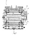
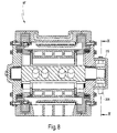
- the curve piece 180 has a shaft 188 at its left end on in a hub 190 of a left housing cover 192 is rotatably mounted. Likewise, the curve piece 180 has on its right end a shaft 194 which in a hub 196 a right housing cover 198 is also rotatably mounted.
- the oscillating piston machine 10 also has one with the general reference numeral 200 provided adjustment mechanism on.
- the adjustment mechanism 200 has a worm gear 203 on.
- the worm gear 203 is driven by a worm wheel 206 as a drive wheel and one with an outer end 202 of the shaft 194 connected gear 204 formed.
- the worm wheel 206 and that Gear 204 mesh with each other.
- the worm wheel 206 has an axis 208 that is perpendicular to the Longitudinal axis 210 of curve piece 180 or to shaft 94 is arranged.
- the adjustment mechanism 200 is covered by a cover 212 completed.
- a drive is shown schematically at 214, the the worm wheel 206 for adjusting the curve piece 180 in Offset forward or backward rotation.
- the drive 214 is also self-locking to lock the curve 180 to ensure the worm gear 203.
- the drive 214 is electronically dependent on the Speed of the oscillating piston machine 10 'controlled to, as before described, early or late ignitions depending on the To enable speed of the oscillating piston machine 10 '.
- the oscillating piston engine 10 distributes several spark plugs, i.e. 1 left and right next to the spark plug 170 in FIG.
- an early or late ignition is carried out a different control of the respective spark plugs Spark generation achieved.
- For early ignition the one required to ignite the fuel-air mixture Spark from that on the left side of spark plug 170 arranged spark plug emitted, and for a late ignition correspondingly from that on the right side of the spark plug 170 arranged spark plug.
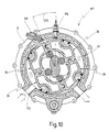
- FIG. 10 another embodiment is one with the general reference number 10 "provided swing piston machine shown.
- the oscillating piston machine 10 "has a difference from that previously described oscillating piston machines 10 and 10 'a fuel injector 218 on.
- the fuel injector 218 is in Rotation direction 40 of the pistons 32, 34, 36, 38 in the housing 12 arranged in front of the ignition point formed by the spark plug 170, namely at a circumferential angle 220 of approximately 25 °.
- the oscillating piston machine 10 is identical to that Swing piston machine 10 with non-rotatable cam piece 88 or with the oscillating piston machine 10 'with a rotatable cam piece 180 trained to change the ignition timing.
- FIG. 11 and 12 show a further embodiment of a the swing piston machine provided with the general reference number 230, which differ from the swing piston machines 10, 10 'and 10 "in terms of the geometry of individual components. In terms of its functional principle, the corresponds Swing piston machine 230, however, the previously described Swing piston machines 10, 10 'or 10 ".
- the oscillating piston machine 230 has an output shaft 232, which is arranged concentrically to the housing axis 234.
- the Output shaft 232 is on an outside of a first ring body 236 designed as a shaft flange.
- the first ring body 236 is over four axially equally distributed axis rods 238, 240 (see FIG. 12) with a second ring body 242 firmly connected.
- the ring bodies 236 and 242 and the four axle rods 238, 240 form a unit, the outer diameter of which is axially continuous is constant.
- the axle rods 238, 240 serve as in the previous ones Embodiments as bearings for the pivoting pistons, which is therefore not dealt with in more detail at this point should.
- This unit from the ring bodies 236, 242 and the axle rods 238, 240 is accommodated in a housing 244, which consists of two axially closing housing covers 246 and 248 and one cylindrical housing part 250 is formed, the cylindrical Housing part 250 has a circular inner wall with continuous has a constant cross-section.
- the inside wall of the housing is in other words, its diameter is continuous homogeneous.
- the first ring body 236 is over a bearing ring 252 and second ring body 242 via a bearing ring 254 rotatable in the Housing 244 stored.
- a curve piece engages in the first ring body 236 256 via a shaft flange 258 and is at rest in it mounted, the ring body 236 over a bearing ring 260 rotates around curve piece 256.
- the curve piece 256 is via an adjustment mechanism 262 Adjustment of the ignition timing is rotatable, the adjustment mechanism 262 in the design and function of the adjustment mechanism 200 in Figs. 6 to 9 corresponds.
- the assembly from the first ring body 236 with the Output shaft 233, from the axle rods 238, 240 and the curve piece 256 can be viewed as a whole after opening the housing cover 246 be pulled out of the housing 244. Conversely, this can Unit pre-assembled outside the housing 244 and as a whole are inserted into the housing 244.
Landscapes
- Engineering & Computer Science (AREA)
- Mechanical Engineering (AREA)
- General Engineering & Computer Science (AREA)
- Transmission Devices (AREA)
- Reciprocating Pumps (AREA)
- Hydraulic Motors (AREA)
- Lubrication Of Internal Combustion Engines (AREA)
- Toys (AREA)
- Engine Equipment That Uses Special Cycles (AREA)
- Cylinder Crankcases Of Internal Combustion Engines (AREA)
- Valve Device For Special Equipments (AREA)
Applications Claiming Priority (3)
| Application Number | Priority Date | Filing Date | Title |
|---|---|---|---|
| DE19639503A DE19639503C1 (de) | 1996-09-26 | 1996-09-26 | Schwenkkolbenmaschine |
| DE19639503 | 1996-09-26 | ||
| PCT/EP1997/005245 WO1998013583A1 (de) | 1996-09-26 | 1997-09-24 | Schwenkkolbenmaschine |
Publications (2)
| Publication Number | Publication Date |
|---|---|
| EP0874949A1 EP0874949A1 (de) | 1998-11-04 |
| EP0874949B1 true EP0874949B1 (de) | 1999-12-15 |
Family
ID=7806921
Family Applications (1)
| Application Number | Title | Priority Date | Filing Date |
|---|---|---|---|
| EP97943899A Expired - Lifetime EP0874949B1 (de) | 1996-09-26 | 1997-09-24 | Schwenkkolbenmaschine |
Country Status (13)
| Country | Link |
|---|---|
| US (1) | US6009847A (cs) |
| EP (1) | EP0874949B1 (cs) |
| JP (1) | JP3354944B2 (cs) |
| KR (1) | KR100289299B1 (cs) |
| CN (1) | CN1091488C (cs) |
| AT (1) | ATE187801T1 (cs) |
| AU (1) | AU4557297A (cs) |
| CA (1) | CA2267346C (cs) |
| CZ (1) | CZ294011B6 (cs) |
| DE (2) | DE19639503C1 (cs) |
| ES (1) | ES2141621T3 (cs) |
| RU (1) | RU2161703C1 (cs) |
| WO (1) | WO1998013583A1 (cs) |
Families Citing this family (17)
| Publication number | Priority date | Publication date | Assignee | Title |
|---|---|---|---|---|
| DE19639503C1 (de) * | 1996-09-26 | 1998-01-15 | Herbert Huettlin | Schwenkkolbenmaschine |
| DE19901110C2 (de) | 1999-01-14 | 2002-06-06 | Herbert Huettlin | Schwenkkolbenmaschine |
| DE10001962B4 (de) * | 2000-01-18 | 2004-07-22 | Hüttlin, Herbert, Dr.h.c. | Rotationskolbenmaschine |
| US7178502B2 (en) * | 2001-06-05 | 2007-02-20 | Paul D. Okulov | Balanced rotary internal combustion engine or cycling volume machine |
| US20030062020A1 (en) * | 2001-06-05 | 2003-04-03 | Okulov Paul D. | Balanced rotary internal combustion engine or cycling volume machine |
| KR200275873Y1 (ko) * | 2001-08-30 | 2002-05-16 | 김동현 | 로타리기관의 피스톤 안내장치 |
| KR20010099195A (ko) * | 2001-09-10 | 2001-11-09 | 김동현 | 로타리 피스톤 |
| DK1472435T3 (da) | 2002-02-06 | 2007-02-12 | Herbert Huettlin | Svingstempelmaskine |
| ATE260404T1 (de) | 2002-04-19 | 2004-03-15 | Herbert Dr H C Huettlin | Rotationskolbenmaschine |
| US6758188B2 (en) * | 2002-07-16 | 2004-07-06 | Joseph B. Wooldridge | Continuous torque inverse displacement asymmetric rotary engine |
| KR100514519B1 (ko) * | 2002-09-25 | 2005-09-14 | 김동현 | 압력식 로타리기관 |
| DE10345342A1 (de) * | 2003-09-19 | 2005-04-28 | Engelhard Arzneimittel Gmbh | Verfahren zur Herstellung eines lagerstabilen Extraktes aus Efeublättern, sowie ein nach diesem Verfahren hergestellter Extrakt |
| DE10361566B4 (de) * | 2003-12-23 | 2006-09-07 | Hüttlin, Herbert, Dr. h.c. | Schwenkkolbenmaschine |
| DE102005010775B3 (de) | 2005-02-25 | 2006-04-20 | Hüttlin, Herbert, Dr. h.c. | Schwenkkolbenmaschine |
| CN101384795B (zh) * | 2006-02-10 | 2012-06-06 | 阿诺德·瓦格纳 | 摆动式活塞发动机 |
| FR2936272B1 (fr) * | 2008-09-22 | 2012-07-13 | Vincent Genissieux | Machine rotative a losange deformable multifonctions |
| RU2619391C1 (ru) * | 2015-12-30 | 2017-05-15 | Общество с ограниченной ответственностью Научное инновационное предприятие "Дельта-Т" | Роторная расширительная машина |
Family Cites Families (15)
| Publication number | Priority date | Publication date | Assignee | Title |
|---|---|---|---|---|
| DE1401969A1 (de) * | 1962-11-24 | 1969-01-30 | Erich Herter | Pendelkolbenmotor |
| DE1551101A1 (de) * | 1967-05-09 | 1970-07-16 | Horst Dierolf | Fliehkolbenverbrennungsmotor |
| CA1045557A (en) * | 1974-03-11 | 1979-01-02 | Theo A.R. Bradley | Rotary engine having cam-controlled pivoted vanes |
| GB1470648A (cs) * | 1974-04-22 | 1977-04-14 | ||
| DE2439319C3 (de) * | 1974-08-16 | 1982-02-25 | Werner 7000 Stuttgart Zink | Rotationskolben-Brennkraftmaschine |
| SU1242629A1 (ru) * | 1984-06-22 | 1986-07-07 | Предприятие П/Я А-7332 | Лопастной мотор |
| SU1355731A2 (ru) * | 1986-03-03 | 1987-11-30 | В. В. Геращенко и Е. Г. Гребень | Объемна роторна машина |
| SU1518555A1 (ru) * | 1987-01-22 | 1989-10-30 | Всесоюзный научно-исследовательский институт природных газов | Роторный двигатель внутреннего сгорани |
| US5051078A (en) * | 1989-07-05 | 1991-09-24 | Lew Hyok S | Rotary pump-flowmeter |
| DE4123176C1 (cs) * | 1991-07-12 | 1992-08-27 | Herbert 7853 Steinen De Huettlin | |
| RU2033542C1 (ru) * | 1991-11-14 | 1995-04-20 | Владимир Алексеевич Булулуков | Роторно-поршневой двигатель внутреннего сгорания |
| DE4138204C1 (cs) * | 1991-11-21 | 1992-12-10 | Friedrich, Werner E., 6708 Neuhofen, De | |
| US5261365A (en) * | 1992-05-26 | 1993-11-16 | Edwards Daniel J | Rotary internal combustion engine |
| DE19639503C1 (de) * | 1996-09-26 | 1998-01-15 | Herbert Huettlin | Schwenkkolbenmaschine |
| JP5135647B2 (ja) | 2000-09-29 | 2013-02-06 | 住友化学株式会社 | ポリエチレン系樹脂組成物及び低光沢性ポリエチレンフィルム |
-
1996
- 1996-09-26 DE DE19639503A patent/DE19639503C1/de not_active Expired - Fee Related
-
1997
- 1997-09-24 AT AT97943899T patent/ATE187801T1/de not_active IP Right Cessation
- 1997-09-24 AU AU45572/97A patent/AU4557297A/en not_active Abandoned
- 1997-09-24 WO PCT/EP1997/005245 patent/WO1998013583A1/de not_active Ceased
- 1997-09-24 CZ CZ1999986A patent/CZ294011B6/cs not_active IP Right Cessation
- 1997-09-24 DE DE59700845T patent/DE59700845D1/de not_active Expired - Fee Related
- 1997-09-24 RU RU99108726/06A patent/RU2161703C1/ru not_active IP Right Cessation
- 1997-09-24 JP JP51526998A patent/JP3354944B2/ja not_active Expired - Fee Related
- 1997-09-24 ES ES97943899T patent/ES2141621T3/es not_active Expired - Lifetime
- 1997-09-24 CN CN97198285A patent/CN1091488C/zh not_active Expired - Fee Related
- 1997-09-24 EP EP97943899A patent/EP0874949B1/de not_active Expired - Lifetime
- 1997-09-24 CA CA002267346A patent/CA2267346C/en not_active Expired - Fee Related
-
1999
- 1999-03-26 US US09/277,654 patent/US6009847A/en not_active Expired - Fee Related
- 1999-03-26 KR KR1019997002586A patent/KR100289299B1/ko not_active Expired - Fee Related
Also Published As
| Publication number | Publication date |
|---|---|
| CZ294011B6 (cs) | 2004-09-15 |
| DE59700845D1 (de) | 2000-01-20 |
| AU4557297A (en) | 1998-04-17 |
| CN1231713A (zh) | 1999-10-13 |
| KR20000048644A (ko) | 2000-07-25 |
| US6009847A (en) | 2000-01-04 |
| HK1012509A1 (en) | 1999-08-06 |
| EP0874949A1 (de) | 1998-11-04 |
| RU2161703C1 (ru) | 2001-01-10 |
| JP2000503092A (ja) | 2000-03-14 |
| CA2267346A1 (en) | 1998-04-02 |
| CA2267346C (en) | 2003-07-08 |
| CN1091488C (zh) | 2002-09-25 |
| CZ98699A3 (cs) | 2000-06-14 |
| ES2141621T3 (es) | 2000-03-16 |
| DE19639503C1 (de) | 1998-01-15 |
| JP3354944B2 (ja) | 2002-12-09 |
| WO1998013583A1 (de) | 1998-04-02 |
| ATE187801T1 (de) | 2000-01-15 |
| KR100289299B1 (ko) | 2001-05-02 |
Similar Documents
| Publication | Publication Date | Title |
|---|---|---|
| DE19639503C1 (de) | Schwenkkolbenmaschine | |
| DE1299189B (de) | Kurventrieb, insbesondere zum Umwandeln von Stroemungsmittel-energie in mechanische Rotationsenergie und umgekehrt | |
| WO2003067033A1 (de) | Schwenkkolbenmaschine | |
| EP1144806B1 (de) | Schwenkkolbenmaschine | |
| EP1355053B1 (de) | Rotationskolbenmaschine | |
| DE69507128T2 (de) | Rotationskolbenmaschine insbesondere wärmekraftmaschine | |
| EP0011762B1 (de) | Rotationskolbenmotor | |
| DE2552575A1 (de) | Kolbenmaschine, insbesondere kolbenkraftmaschine | |
| DE2512547A1 (de) | Drehkolbenmaschine | |
| DE3528139C2 (de) | Verbrennungsmotor | |
| EP0136565A2 (de) | Aggregat bestehend aus einer Hubkolbenmaschine und einem Getriebe | |
| WO1995034749A1 (de) | Verbrennungsmotor | |
| EP1856375B1 (de) | Schwenkkolbenmaschine | |
| EP2205832B1 (de) | Kolbenmaschine | |
| DE10001962B4 (de) | Rotationskolbenmaschine | |
| EP0071890A1 (de) | Hub- oder Rotationskolbenmaschine mit grössenveränderlichem Endverdichtungsraum | |
| EP1226338B1 (de) | Drehkolbenmaschine | |
| DE885023C (de) | Brennkraftmaschine mit Zylindern, deren Achsen sich parallel zur Achse der Maschinenwelle erstrecken | |
| DE3444023A1 (de) | Drehkolbenmaschine | |
| EP0787251B1 (de) | Verbrennungskraftmaschine | |
| DE3819665A1 (de) | Rotationskolbenmotor | |
| DE3725806A1 (de) | Drehkolbenverdichter | |
| DE2731534C3 (de) | Rotationskolben-Brennkraftmaschine | |
| DE1526416A1 (de) | Rotations-Brennkraftmaschine | |
| DE2608057A1 (de) | Drehkolbenmotor |
Legal Events
| Date | Code | Title | Description |
|---|---|---|---|
| PUAI | Public reference made under article 153(3) epc to a published international application that has entered the european phase |
Free format text: ORIGINAL CODE: 0009012 |
|
| 17P | Request for examination filed |
Effective date: 19980818 |
|
| AK | Designated contracting states |
Kind code of ref document: A1 Designated state(s): AT BE CH DE DK ES FI FR GB IE IT LI NL PT SE |
|
| AX | Request for extension of the european patent |
Free format text: LT PAYMENT 980818;RO PAYMENT 980818;SI PAYMENT 980818 |
|
| GRAG | Despatch of communication of intention to grant |
Free format text: ORIGINAL CODE: EPIDOS AGRA |
|
| 17Q | First examination report despatched |
Effective date: 19981125 |
|
| GRAG | Despatch of communication of intention to grant |
Free format text: ORIGINAL CODE: EPIDOS AGRA |
|
| GRAH | Despatch of communication of intention to grant a patent |
Free format text: ORIGINAL CODE: EPIDOS IGRA |
|
| GRAH | Despatch of communication of intention to grant a patent |
Free format text: ORIGINAL CODE: EPIDOS IGRA |
|
| GRAA | (expected) grant |
Free format text: ORIGINAL CODE: 0009210 |
|
| AK | Designated contracting states |
Kind code of ref document: B1 Designated state(s): AT BE CH DE DK ES FI FR GB IE IT LI NL PT SE |
|
| AX | Request for extension of the european patent |
Free format text: LT PAYMENT 19980818;RO PAYMENT 19980818;SI PAYMENT 19980818 |
|
| LTIE | Lt: invalidation of european patent or patent extension | ||
| PG25 | Lapsed in a contracting state [announced via postgrant information from national office to epo] |
Ref country code: NL Free format text: LAPSE BECAUSE OF FAILURE TO SUBMIT A TRANSLATION OF THE DESCRIPTION OR TO PAY THE FEE WITHIN THE PRESCRIBED TIME-LIMIT Effective date: 19991215 Ref country code: FI Free format text: LAPSE BECAUSE OF FAILURE TO SUBMIT A TRANSLATION OF THE DESCRIPTION OR TO PAY THE FEE WITHIN THE PRESCRIBED TIME-LIMIT Effective date: 19991215 |
|
| REF | Corresponds to: |
Ref document number: 187801 Country of ref document: AT Date of ref document: 20000115 Kind code of ref document: T |
|
| REG | Reference to a national code |
Ref country code: CH Ref legal event code: EP |
|
| GBT | Gb: translation of ep patent filed (gb section 77(6)(a)/1977) |
Effective date: 19991216 |
|
| REF | Corresponds to: |
Ref document number: 59700845 Country of ref document: DE Date of ref document: 20000120 |
|
| ET | Fr: translation filed | ||
| ITF | It: translation for a ep patent filed | ||
| REG | Reference to a national code |
Ref country code: IE Ref legal event code: FG4D |
|
| PG25 | Lapsed in a contracting state [announced via postgrant information from national office to epo] |
Ref country code: PT Free format text: LAPSE BECAUSE OF FAILURE TO SUBMIT A TRANSLATION OF THE DESCRIPTION OR TO PAY THE FEE WITHIN THE PRESCRIBED TIME-LIMIT Effective date: 20000315 Ref country code: DK Free format text: LAPSE BECAUSE OF FAILURE TO SUBMIT A TRANSLATION OF THE DESCRIPTION OR TO PAY THE FEE WITHIN THE PRESCRIBED TIME-LIMIT Effective date: 20000315 |
|
| REG | Reference to a national code |
Ref country code: ES Ref legal event code: FG2A Ref document number: 2141621 Country of ref document: ES Kind code of ref document: T3 |
|
| NLV1 | Nl: lapsed or annulled due to failure to fulfill the requirements of art. 29p and 29m of the patents act | ||
| PG25 | Lapsed in a contracting state [announced via postgrant information from national office to epo] |
Ref country code: AT Free format text: LAPSE BECAUSE OF NON-PAYMENT OF DUE FEES Effective date: 20000924 |
|
| PG25 | Lapsed in a contracting state [announced via postgrant information from national office to epo] |
Ref country code: BE Free format text: LAPSE BECAUSE OF NON-PAYMENT OF DUE FEES Effective date: 20000930 |
|
| PLBE | No opposition filed within time limit |
Free format text: ORIGINAL CODE: 0009261 |
|
| STAA | Information on the status of an ep patent application or granted ep patent |
Free format text: STATUS: NO OPPOSITION FILED WITHIN TIME LIMIT |
|
| PG25 | Lapsed in a contracting state [announced via postgrant information from national office to epo] |
Ref country code: IE Free format text: LAPSE BECAUSE OF NON-PAYMENT OF DUE FEES Effective date: 20001116 |
|
| 26N | No opposition filed | ||
| REG | Reference to a national code |
Ref country code: IE Ref legal event code: FD4D |
|
| BERE | Be: lapsed |
Owner name: HUTTLIN HERBERT Effective date: 20000930 |
|
| PG25 | Lapsed in a contracting state [announced via postgrant information from national office to epo] |
Ref country code: LI Free format text: LAPSE BECAUSE OF NON-PAYMENT OF DUE FEES Effective date: 20010930 Ref country code: CH Free format text: LAPSE BECAUSE OF NON-PAYMENT OF DUE FEES Effective date: 20010930 |
|
| REG | Reference to a national code |
Ref country code: GB Ref legal event code: IF02 |
|
| REG | Reference to a national code |
Ref country code: CH Ref legal event code: PL |
|
| PGFP | Annual fee paid to national office [announced via postgrant information from national office to epo] |
Ref country code: FR Payment date: 20040625 Year of fee payment: 8 |
|
| PGFP | Annual fee paid to national office [announced via postgrant information from national office to epo] |
Ref country code: SE Payment date: 20040909 Year of fee payment: 8 |
|
| PGFP | Annual fee paid to national office [announced via postgrant information from national office to epo] |
Ref country code: GB Payment date: 20040913 Year of fee payment: 8 |
|
| PGFP | Annual fee paid to national office [announced via postgrant information from national office to epo] |
Ref country code: ES Payment date: 20040920 Year of fee payment: 8 |
|
| PG25 | Lapsed in a contracting state [announced via postgrant information from national office to epo] |
Ref country code: IT Free format text: LAPSE BECAUSE OF NON-PAYMENT OF DUE FEES Effective date: 20050924 Ref country code: GB Free format text: LAPSE BECAUSE OF NON-PAYMENT OF DUE FEES Effective date: 20050924 |
|
| PG25 | Lapsed in a contracting state [announced via postgrant information from national office to epo] |
Ref country code: SE Free format text: LAPSE BECAUSE OF NON-PAYMENT OF DUE FEES Effective date: 20050925 |
|
| PG25 | Lapsed in a contracting state [announced via postgrant information from national office to epo] |
Ref country code: ES Free format text: LAPSE BECAUSE OF NON-PAYMENT OF DUE FEES Effective date: 20050926 |
|
| EUG | Se: european patent has lapsed | ||
| GBPC | Gb: european patent ceased through non-payment of renewal fee |
Effective date: 20050924 |
|
| PG25 | Lapsed in a contracting state [announced via postgrant information from national office to epo] |
Ref country code: FR Free format text: LAPSE BECAUSE OF NON-PAYMENT OF DUE FEES Effective date: 20060531 |
|
| REG | Reference to a national code |
Ref country code: FR Ref legal event code: ST Effective date: 20060531 |
|
| PGFP | Annual fee paid to national office [announced via postgrant information from national office to epo] |
Ref country code: DE Payment date: 20061028 Year of fee payment: 10 |
|
| REG | Reference to a national code |
Ref country code: ES Ref legal event code: FD2A Effective date: 20050926 |
|
| PG25 | Lapsed in a contracting state [announced via postgrant information from national office to epo] |
Ref country code: DE Free format text: LAPSE BECAUSE OF NON-PAYMENT OF DUE FEES Effective date: 20080401 |