EP0875325A1 - Drahtsäge, Montage-, Wartungs- und Einfahrstation für eine Drahtführungsrollen-Einheit der Drahtsäge und Verfahren zum Auswechseln der Drahtführungs-rollen-Einheit - Google Patents
Drahtsäge, Montage-, Wartungs- und Einfahrstation für eine Drahtführungsrollen-Einheit der Drahtsäge und Verfahren zum Auswechseln der Drahtführungs-rollen-Einheit Download PDFInfo
- Publication number
- EP0875325A1 EP0875325A1 EP98107481A EP98107481A EP0875325A1 EP 0875325 A1 EP0875325 A1 EP 0875325A1 EP 98107481 A EP98107481 A EP 98107481A EP 98107481 A EP98107481 A EP 98107481A EP 0875325 A1 EP0875325 A1 EP 0875325A1
- Authority
- EP
- European Patent Office
- Prior art keywords
- guide roller
- wire guide
- wire
- roller unit
- saw
- Prior art date
- Legal status (The legal status is an assumption and is not a legal conclusion. Google has not performed a legal analysis and makes no representation as to the accuracy of the status listed.)
- Ceased
Links
Images



Classifications
-
- B—PERFORMING OPERATIONS; TRANSPORTING
- B28—WORKING CEMENT, CLAY, OR STONE
- B28D—WORKING STONE OR STONE-LIKE MATERIALS
- B28D5/00—Fine working of gems, jewels, crystals, e.g. of semiconductor material; apparatus or devices therefor
- B28D5/04—Fine working of gems, jewels, crystals, e.g. of semiconductor material; apparatus or devices therefor by tools other than rotary type, e.g. reciprocating tools
- B28D5/045—Fine working of gems, jewels, crystals, e.g. of semiconductor material; apparatus or devices therefor by tools other than rotary type, e.g. reciprocating tools by cutting with wires or closed-loop blades
-
- B—PERFORMING OPERATIONS; TRANSPORTING
- B23—MACHINE TOOLS; METAL-WORKING NOT OTHERWISE PROVIDED FOR
- B23D—PLANING; SLOTTING; SHEARING; BROACHING; SAWING; FILING; SCRAPING; LIKE OPERATIONS FOR WORKING METAL BY REMOVING MATERIAL, NOT OTHERWISE PROVIDED FOR
- B23D57/00—Sawing machines or sawing devices not covered by one of the preceding groups B23D45/00 - B23D55/00
- B23D57/003—Sawing machines or sawing devices working with saw wires, characterised only by constructional features of particular parts
- B23D57/0053—Sawing machines or sawing devices working with saw wires, characterised only by constructional features of particular parts of drives for saw wires; of wheel mountings; of wheels
-
- B—PERFORMING OPERATIONS; TRANSPORTING
- B23—MACHINE TOOLS; METAL-WORKING NOT OTHERWISE PROVIDED FOR
- B23D—PLANING; SLOTTING; SHEARING; BROACHING; SAWING; FILING; SCRAPING; LIKE OPERATIONS FOR WORKING METAL BY REMOVING MATERIAL, NOT OTHERWISE PROVIDED FOR
- B23D57/00—Sawing machines or sawing devices not covered by one of the preceding groups B23D45/00 - B23D55/00
- B23D57/0007—Sawing machines or sawing devices not covered by one of the preceding groups B23D45/00 - B23D55/00 using saw wires
-
- B—PERFORMING OPERATIONS; TRANSPORTING
- B23—MACHINE TOOLS; METAL-WORKING NOT OTHERWISE PROVIDED FOR
- B23D—PLANING; SLOTTING; SHEARING; BROACHING; SAWING; FILING; SCRAPING; LIKE OPERATIONS FOR WORKING METAL BY REMOVING MATERIAL, NOT OTHERWISE PROVIDED FOR
- B23D57/00—Sawing machines or sawing devices not covered by one of the preceding groups B23D45/00 - B23D55/00
- B23D57/003—Sawing machines or sawing devices working with saw wires, characterised only by constructional features of particular parts
- B23D57/0061—Sawing machines or sawing devices working with saw wires, characterised only by constructional features of particular parts of devices for guiding or feeding saw wires
Definitions
- the invention relates to a wire saw for separating Disks from a workpiece, especially a wire saw Manufacture of semiconductor wafers.
- the wire saw includes one Saw head, in which at least two wire guide rollers each are rotatably supported between a loose and a fixed bearing, with adjacent wire guide rollers along with one around they wound wire to form a wire gate.
- the wire frame acts as a cutting tool.
- a sawing suspension can be dispensed with if a saw wire with bound cutting grain is used.
- the invention further relates to an assembly station and a maintenance and entry station for a wire guide roller unit and a method for replacing the Wire guide roller unit.
- a wire saw of the type mentioned with a saw head, in which the wire guide rollers each between a lot and a fixed bearing in a saw head is, for example described in EP-733 429 A1.
- This Wire saw can be a variety of semiconductor wafers of a certain Thickness from a crystal piece during a cutting process be separated. The thickness of the wafers is determined by the distance between the turns of the saw wire have in the wire gate. This distance is again through grooves in the surface of the wire guide rollers, in which the Wire runs, essentially predetermined.
- the wire saw has also via a heating / cooling system for tempering the wire guide rollers and the associated loose and fixed bearings. Unwanted saw wire displacement due to thermal expansion machine parts should be kept as small as possible in this way will.
- a change of the covering of a wire guide roller or a Wire guide roller change is particularly necessary if the separation result deteriorates because the coating is worn or, if intended, the thickness below disks to be cut to a new value. A deterioration in the separation result can also result in damaged Point out camp.
- the present invention solves the problem with a Downtime associated with wire guide roller or bearing change shorten the wire saw and change the base simplify.
- the invention relates to a wire saw of the type mentioned, which is characterized in that each wire guide roller and the associated floating and fixed bearing a wire guide roller unit form that only as a whole from the saw head can be removed.
- the wire guide roller and the bearing shafts also form one rigid unit that is balanced as such and its bearing seats and pad holder can be manufactured in one operation can.
- wire guide roller and floating and fixed bearing not only allows for a wire guide roller unit rapid expansion of the wire guide roller and the bearings, but also opens up the possibility of the removed wire guide roller in an assembly station with a new covering provided, following and reinstalling the Wire guide roller unit retracting into the wire saw Wire saw to reach the necessary operating temperature can be omitted.
- the present invention therefore also solves the problem of misalignment to avoid simplifying the bearing construction and to ensure a smooth run.
- the downtime of the wire saw is significantly reduced if the wire guide roller unit, which is taken from the wire saw has already been opened by another in an assembly station their use prepared wire guide roller unit replaced becomes.
- the bearings of the wire guide roller unit removed from the wire saw can also be repaired outside of the wire saw or be replaced. It is suggested the wire guide roller unit following a repair or Change of bearings in a maintenance and entry station. Meanwhile, the wire saw can be used, for example prepared in another maintenance and entry station and retracted wire guide roller unit, for production of discs are used. The downtime the wire saw is shortened due to the absence of a run-in phase in the wire saw and sawing a test workpiece the duration of the exchange of wire guide roller units.
- the invention finally relates to a method for Replacing a wire guide roller unit of a wire saw for cutting slices from a workpiece.
- the procedure is characterized in that the wire guide roller unit, which is a coated wire guide roller and comprises a loose and a fixed bearing, from a working position is axially displaced into a release position and with Is removed from the wire saw using a manipulator and a preheated wire guide roller unit in the working position brought.
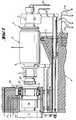
- the wire guide roller 1 is between a floating bearing 2 and a fixed bearing 3 in a saw head 4 rotatably mounted. In the saw head are preferred 2 to 4 wire guide rollers housed, of which at least one is driven.
- the cylindrical body of the Wire guide roller is on the sides to a bearing shaft 5 rejuvenated.
- the floating bearing 2 and the fixed bearing 3 sit on the Bearing shaft and form a wire guide roller unit with the wire guide roller 1 6.
- the wire guide roller shown is powered by a motor 9, the torque of which Clutch is transmitted directly, driven.
- the wire guide roller unit is tempered with Help of a heating / cooling system 12.
- This includes supply lines 13 and 14, with channels inside the wire guide roller and the floating bearing are connected, and by the one Temperature control circuit in the wire guide roller and in Floating bearing is maintained.
- the heating / cooling system also includes Temperature control segments 15 with corresponding supply lines 16 for tempering the fixed bearing from the outside. They lie on the slightly conical surface of the fixed bearing and are against the lateral surface by springs pressed. With the help of a sealing air line 17, a steady air flow into the area of the fixed bearing and In this way, components of the sawing suspension can be prevented or the abrasion generated during the separation process in the Fixed bearings can penetrate.
- an expansion aid For removing the wire guide roller unit from the wire saw an expansion aid is planned.
- this includes one with a spindle drive 18th provided linear slide system 19 with which the Wire guide roller unit 6 in a release position axially can be moved.
- the saw wire must be removed beforehand and the locking by the swing clamp 10 and clamping elements 11 be canceled.
- the supply lines 13 and 14 separated from the wire guide roller unit be, with self-closing at the separation points Valves are provided.
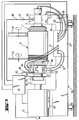
- FIG. 2 shows a situation in which the Wire guide roller unit already in the release position located.
- the embodiment of the wire saw shown has one Coupling between the drive and the fixed bearing on the when moving the wire guide roller unit to the release position into a half 20 remaining in the saw head and one with the wire guide roller unit 6 in connection Half 21 is automatically separated.
- the sealing air line 17 automatically separated.
- the wire guide roller unit In the release position the wire guide roller unit can be manipulated lifted out of the saw head in the direction of the arrow and, for example be transferred to an assembly station. To avoid long downtimes of the wire saw is preferred immediately after removing the wire guide roller unit, one already prepared for its use Wire guide roller unit in one, according to the removal reverse order, placed in the working position.
- the removed wire guide roller unit is overhauled, for example cleaned and provided with a new covering and then returned to their original location in the saw head becomes.
- the wire guide roller unit contact the temperature control segments 15 automatically on the outer surface the fixed bearing 3 (Fig. 1). There are no supply lines be connected.
- FIG. 3 shows an assembly station 22 with a wire guide roller unit 6 accommodated therein and part of a manipulator suitable for moving the wire guide roller unit.
- the manipulator expediently has pliers-like grippers 23 which laterally enclose the wire guide roller unit and an axis of rotation 24 which enables the wire guide roller unit to be rotated through 90 °.
- the wire guide roller unit removed from the saw head is rotated by the said angle and placed on supporting surfaces 25 of the assembly station or, if appropriate, hung in and fixed thereon with holding elements 26.
- the assembly station 22 is equipped with a heating / cooling system 27 for tempering the wire guide roller unit 6.
- the floating bearing is tempered from the outside via the supply lines 28.
- tempering segments 30 with corresponding supply lines 31 are provided, which can be moved to the fixed bearing with linear feed elements 32.
- a tool 33 is provided in the assembly station, with which the pad 7, which is cast onto a one-piece sleeve 34 in the exemplary embodiment shown, can be detached from the wire guide roller.
- the wire guide roller unit can also consist entirely of CFRP material.
- the assembly station can be designed as a movable assembly carriage that can be moved up to the wire saw if necessary. Another embodiment provides for the assembly station and possibly also the manipulator to be attached to the wire saw. Finally, the assembly station can also be designed so that it can accommodate more than one wire guide roller unit.
- the wire guide roller unit 6 is located outside the wire saw on a repair table 35 and is on this is supported by supports 47. After finishing the necessary The wire guide roller unit will work in one Maintenance and entry station transferred.
- FIG. 5 shows a suitable maintenance and entry station 36, in which the wire guide roller unit 6 is placed on bearing supports 46.
- a motor 37 for driving the wire guide roller unit.
- the motor is coupled to the wire guide roller unit by moving a linear guide 38.
- the repaired or replaced bearings 2 and 3 are driven by the motor according to a defined program at certain speeds.
- the test run the temperatures at the bearings and the vibrations caused by the rotating wire guide roller unit are measured.
- the test run which can take several hours, is carried out with the aim of preparing the wire guide roller unit for use in the wire saw.
- the wire guide roller unit is to be brought to a constant operating temperature and a low-vibration rotary movement of the wire guide roller unit is to be achieved.
- the test run is controlled by a device 41 for monitoring the retraction of the wire guide roller unit.
- the maintenance and entry station 36 like the assembly station according to FIG. 3, is equipped with a heating / cooling system 27 for tempering the wire guide roller unit 6.
- the temperatures of the floating and fixed bearings are measured by temperature sensors 39 and continuously reported to the monitoring device 41 via signal lines 40.
- the signal lines 40 are connected to the temperature sensors via quick-action couplings 42.
- the temperature sensors can also be connected to a wire saw controller via the quick couplings.
- Vibration sensors 43 are also connected to the monitoring device 41 and track the vibration development when the wire guide roller unit runs. If the vibration values still considered permissible are exceeded, the test run is stopped and the wire guide roller unit is balanced.
- means are also provided in the maintenance and entry station 36 with which a damaged or worn covering of the wire guide roller can be overhauled.
- These means can include, for example, a cylindrical grinding tool 44 and a groove grinding tool 45. The surface is ground using the cylindrical grinding tool, and guide grooves are ground in the surface using the groove grinding tool.
- the drive of the grinding tools is not shown in Fig.5.
- Prepared wire guide roller unit can be installed into the wire saw and covering with sawing wire immediately be used for the production of discs. Downtimes The wire saw can be used for the duration of the exchange of wire guide roller units by a wire guide roller unit after its removal from the Wire saw immediately by doing in the manner described Replaceable wire guide roller unit replaced becomes. Run-in phases in the wire saw and sawing test workpieces are saved in this way.
Landscapes
- Engineering & Computer Science (AREA)
- Mechanical Engineering (AREA)
- Finish Polishing, Edge Sharpening, And Grinding By Specific Grinding Devices (AREA)
- Processing Of Stones Or Stones Resemblance Materials (AREA)
Abstract
Description
Mit Hilfe des Heiz-/Kühlsystems wird die Drahtführungsrollen-Einheit während ihres Aufenthalts in der Montagestation vortemperiert, so daß nach einem anschließenden Einbau in die Drahtsäge keine Aufwärmphase notwendig ist, während der die Drahtführungsrolle auf Betriebstemperatur gebracht werden muß. Zur Wiederherstellung der Betriebsbereitschaft der Drahtsäge genügt es, die Drahtführungsrollen-Einheit dem umgekehrten Ablauf ihrer Entnahme entsprechend in die Arbeitsposition im Sägekopf zu bringen und die Drahtführungsrollen mit einem neuen Sägedraht zu belegen.
Die Montagestation kann als verfahrbarer Montagewagen ausgebildet sein, der bei Bedarf an die Drahtsäge herangefahren wird. Eine andere Ausführungsform sieht vor, die Montagestation und gegebenfalls auch den Manipulator an die Drahtsäge anzubauen. Schließlich kann die Montagestation auch so ausgebildet sein, daß sie mehr als eine Drahtführungsrollen-Einheit aufnehmen kann.
An die Überwachungseinrichtung 41 sind auch Schwingungssensoren 43 angeschlossen, die die Schwingungsentwicklung beim Lauf der Drahtführungsrollen-Einheit verfolgen. Bei einem Überschreiten von als noch zulässig erachteten Schwingungswerten wird der Testlauf abgebrochen, und die Drahtführungsrollen-Einheit ausgewuchtet.
Gemäß einer bevorzugten Ausführungsform sind in der Wartungs- und Einfahrstation 36 auch Mittel vorgesehen, mit denen ein beschädigter oder verschlissener Belag der Drahtführungsrolle überholt werden kann. Diese Mittel können beispielsweise ein Rundschleifwerkzeug 44 und ein Rillenschleifwerkzeug 45 umfassen. Mit dem Rundschleifwerkzeug wird der Belag überschliffen, und mit dem Rillenschleifwerkzeug werden Führungsrillen in den Belag eingeschliffen. Der Antrieb der Schleifwerkzeuge ist in Fig.5 nicht dargestellt.
Claims (15)
- Drahtsäge zum Abtrennen von Scheiben von einem Werkstück, mit einem Sägekopf, in dem mindestens zwei Drahtführungsrollen jeweils zwischen einem Los- und einem Festlager drehbar gelagert sind, wobei benachbarte Drahtführungsrollen zusammen mit einem um sie gewickelten Draht ein Drahtgatter ausbilden, dadurch gekennzeichnet, daß jede Drahtführungsrolle und das ihr zugeordnete Los- und Festlager eine Drahtführungsrollen-Einheit bilden, die nur als Ganzes aus dem Sägekopf entfernt werden kann.
- Drahtsäge nach Anspruch 1, gekennzeichnet durch eine im Sägekopf vorgesehene Ausbauhilfe, mit der die Drahtführungsrollen-Einheit axial verschoben werden kann.
- Drahtsäge nach Anspruch 1 oder Anspruch 2, gekennzeichnet durch Temperiersegmente zum Temperieren des Festlagers, die beim Entfernen der Drahtführungsrollen-Einheit im Sägekopf bleiben und bei einem Einbau der Drahtführungsrollen-Einheit in den Sägekopf automatisch an einer Mantelfläche des Festlagers kontaktieren.
- Drahtsäge nach einem der Ansprüche 1 bis 3, dadurch gekennzeichnet, daß die Drahtführungsrolle und deren Lagerwellen eine rotierende Einheit bilden, die beim Ausbau der Drahtführungsrolle aus der Drahtsäge nicht aufgetrennt werden muß.
- Montagestation für eine Drahtführungsrollen-Einheit mit einer Drahtführungsrolle, einem Los- und einem Festlager, umfassenda) Stützflächen zum Abstützen der Drahtführungsrollen-Einheit;b) Halteelemente zum Fixieren der Drahtführungsrollen-Einheit auf den Stützflächen;c) ein Heiz-/Kühlsystem zum Temperieren der Drahtführungsrollen-Einheit, undd) Mittel zum Lösen eines Belages von der Drahtführungsrolle.
- Montagestation nach Anspruch 5, dadurch gekennzeichnet, daß das Heiz-/Kühlsystem Mittel zum Temperieren der Drahtführungsrollen-Einheit von innen und des Los- und des Festlagers von außen besitzt.
- Wartungs- und Einfahrstation für eine Drahtführungsrollen-Einheit mit einer Drahtführungsrolle, einem Los- und einem Festlager, umfassenda) Lagerstützen zum Abstützen der Drahtführungsrollen-Einheit;b) ein Heiz-/Kühlsystem zum Temperieren der Drahtführungsrollen-Einheit;c) einen Antrieb zum Einfahren der Drahtführungsrollen-Einheit; undd) eine Einrichtung zur Überwachung des Einfahrens der Drahtführungsrollen-Einheit.
- Station nach Anspruch 7, dadurch gekennzeichnet, daß die Einrichtung zur Überwachung des Einfahrens der Drahtführungsrollen-Einheit mit Sensoren ausgestattet ist, die die Temperatur der Lager und den Rundlauf und die Schwingungen der Drahtführungsrollen-Einheit messen.
- Station nach Anspruch 7 oder 8, gekennzeichnet durch eine Einrichtung zum Rund- und Rillenschleifen eines Belages der Drahtführungsrolle.
- Verfahren zum Auswechseln einer Drahtführungsrollen-Einheit einer Drahtsäge zum Abtrennen von Scheiben von einem Werkstück, dadurch gekennzeichnet, daß die Drahtführungsrollen-Einheit, die eine mit einem Belag versehene Drahtführungsrolle und ein Los- und ein Festlager umfaßt, aus einer Arbeitsposition in eine Freigabeposition axial verschoben wird und mit Hilfe eines Manipulators aus der Drahtsäge entfernt wird und eine vortemperierte Drahtführungsrollen-Einheit in die Arbeitsposition gebracht wird.
- Verfahren nach Anspruch 10, dadurch gekennzeichnet, daß die aus der Drahtsäge entfernte Drahtführungsrollen-Einheit in einer Montagestation mit einem neuen Belag versehen und vortemperiert wird.
- Verfahren nach Anspruch 10, dadurch gekennzeichnet, daß die Lager der aus der Drahtsäge entfernten Drahtführungsrollen- Einheit repariert oder ausgetauscht werden, und die Drahtführungsrollen-Einheit in eine Wartungs- und Einfahrstation überführt wird, in der sie gegebenenfalls ausgewuchtet und auf Rundlauf geprüft, eingefahren und vortemperiert wird.
- Verfahren nach Anspruch 12, dadurch gekennzeichnet, daß der Belag der Drahtführungsrolle in der Wartungs- und Einfahrstation überholt wird.
- Drahtsäge nach einem der Ansprüche 1 bis 3, gekennzeichnet durch eine von einer Drahtführungsrolle lösbaren Hülse aus mit Kohlefasern verstärktem Kunststoff.
- Drahtsäge nach einem der Ansprüche 1 bis 3, gekennzeichnet durch eine Drahtführungsrollen-Einheit aus mit Kohlefasern verstärktem Kunststoff.
Applications Claiming Priority (2)
| Application Number | Priority Date | Filing Date | Title |
|---|---|---|---|
| DE19717379A DE19717379A1 (de) | 1997-04-24 | 1997-04-24 | Drahtsäge und Montagestation für eine Drahtführungsrolle einer Drahtsäge sowie Verfahren zum Auswechseln einer Drahtführungsrolle |
| DE19717379 | 1997-04-24 |
Publications (1)
| Publication Number | Publication Date |
|---|---|
| EP0875325A1 true EP0875325A1 (de) | 1998-11-04 |
Family
ID=7827653
Family Applications (1)
| Application Number | Title | Priority Date | Filing Date |
|---|---|---|---|
| EP98107481A Ceased EP0875325A1 (de) | 1997-04-24 | 1998-04-24 | Drahtsäge, Montage-, Wartungs- und Einfahrstation für eine Drahtführungsrollen-Einheit der Drahtsäge und Verfahren zum Auswechseln der Drahtführungs-rollen-Einheit |
Country Status (6)
| Country | Link |
|---|---|
| US (1) | US6050254A (de) |
| EP (1) | EP0875325A1 (de) |
| JP (1) | JP2942954B2 (de) |
| KR (1) | KR100281442B1 (de) |
| DE (1) | DE19717379A1 (de) |
| SG (1) | SG74049A1 (de) |
Cited By (4)
| Publication number | Priority date | Publication date | Assignee | Title |
|---|---|---|---|---|
| CN102689368A (zh) * | 2011-03-23 | 2012-09-26 | 硅电子股份公司 | 由工件切分晶圆的方法 |
| CN102689369A (zh) * | 2011-03-23 | 2012-09-26 | 硅电子股份公司 | 由工件切分晶圆的方法 |
| CN104690840A (zh) * | 2013-12-06 | 2015-06-10 | 硅电子股份公司 | 借助线锯从工件切分出晶片的方法 |
| CN107414650A (zh) * | 2017-07-14 | 2017-12-01 | 芜湖鼎瀚再制造技术有限公司 | 一种针对瓦楞辊再制造用的自动磨削除锈修复装置 |
Families Citing this family (10)
| Publication number | Priority date | Publication date | Assignee | Title |
|---|---|---|---|---|
| ITPR20000040A1 (it) * | 2000-06-27 | 2001-12-27 | Sasib Labelling Machinery S P | Rullo di taglio in una macchina etichettatrice con introduzione in continuo di un film di etichette in bobina |
| KR100544503B1 (ko) * | 2001-12-03 | 2006-01-24 | 주식회사 포스코 | 압연롤 간격발생장치 |
| US20030170948A1 (en) * | 2002-03-07 | 2003-09-11 | Memc Electronic Materials, Inc. | Method and apparatus for slicing semiconductor wafers |
| EP2242629A1 (de) * | 2008-02-11 | 2010-10-27 | MEMC Electronic Materials, Inc. | Mit kohlenstoffnanoröhrchen verstärkter seilsägebalken zum sägen von ingots in wafer mit einer seilsäge |
| DE102008044805B4 (de) * | 2008-08-28 | 2016-06-09 | Solarworld Industries Sachsen Gmbh | Drahtüberwachung |
| DE102009016545A1 (de) | 2009-04-06 | 2010-10-28 | Xperion Gmbh | Leitrolle für Drähte |
| JP5452124B2 (ja) * | 2009-08-04 | 2014-03-26 | Sumco Techxiv株式会社 | ワイヤソー用のメインローラ、および、ワイヤソー |
| CN102548696A (zh) * | 2009-09-18 | 2012-07-04 | 应用材料公司 | 供线锯装置所用的滑轮、线锯装置及操作方法 |
| DE102019207719A1 (de) * | 2019-05-27 | 2020-12-03 | Siltronic Ag | Verfahren zum Abtrennen einer Vielzahl von Scheiben von Werkstücken während einer Anzahl von Abtrennvorgängen mittels einer Drahtsäge und Halbleiterscheibe aus einkristallinem Silizium |
| CN111702582B (zh) * | 2020-07-02 | 2021-07-13 | 丽水学院 | 一种滑块间距调节平面磨床及使用方法 |
Citations (5)
| Publication number | Priority date | Publication date | Assignee | Title |
|---|---|---|---|---|
| JPH01177960A (ja) * | 1987-12-28 | 1989-07-14 | Sumitomo Metal Ind Ltd | ワイヤ式切断装置におけるワイヤ張設機構 |
| CH677895A5 (en) * | 1988-11-08 | 1991-07-15 | Charles Hauser | Wire cutting appts. for silicon - has steel wires passing around cylinders and through abrasive liquid mixture to slice silicon for electronic components |
| CH679136A5 (en) * | 1989-04-03 | 1991-12-31 | Charles Hauser | Abrasive wire cutting unit - has interchangeable wire guide cylinders for adjustment of spacing between wires |
| JPH0820016A (ja) * | 1994-07-07 | 1996-01-23 | Tokyo Seimitsu Co Ltd | ワイヤーソー装置 |
| EP0733429A1 (de) * | 1995-03-23 | 1996-09-25 | Wacker Siltronic Gesellschaft für Halbleitermaterialien Aktiengesellschaft | Drahtsäge und Verfahren zum Abtrennen von Scheiben von einem Werkstück |
Family Cites Families (7)
| Publication number | Priority date | Publication date | Assignee | Title |
|---|---|---|---|---|
| DE733429C (de) * | 1938-09-27 | 1943-03-26 | Heliowatt Werke Elek Zitaets A | Rundfunk-Kofferempfaenger, in dessen beweglichen Rueckendeckel eine Rahmenantenne eingebaut ist |
| US3831576A (en) * | 1971-11-22 | 1974-08-27 | Motorola Inc | Machine and method for cutting brittle materials using a reciprocating cutting wire |
| JP2516717B2 (ja) * | 1991-11-29 | 1996-07-24 | 信越半導体株式会社 | ワイヤソ―及びその切断方法 |
| JP2755907B2 (ja) * | 1994-06-28 | 1998-05-25 | 信越半導体株式会社 | ワイヤソー用溝ローラ |
| US5896851A (en) * | 1995-04-21 | 1999-04-27 | Tokyo Seimitsu Co., Ltd. | Wire saw |
| US5564409A (en) * | 1995-06-06 | 1996-10-15 | Corning Incorporated | Apparatus and method for wire cutting glass-ceramic wafers |
| CH691037A5 (fr) * | 1996-02-06 | 2001-04-12 | Hct Shaping Systems Sa | Dispositif de sciage par fil. |
-
1997
- 1997-04-24 DE DE19717379A patent/DE19717379A1/de not_active Withdrawn
-
1998
- 1998-04-07 US US09/056,831 patent/US6050254A/en not_active Expired - Fee Related
- 1998-04-09 SG SG1998000826A patent/SG74049A1/en unknown
- 1998-04-22 JP JP10112218A patent/JP2942954B2/ja not_active Expired - Lifetime
- 1998-04-23 KR KR1019980014547A patent/KR100281442B1/ko not_active Expired - Fee Related
- 1998-04-24 EP EP98107481A patent/EP0875325A1/de not_active Ceased
Patent Citations (5)
| Publication number | Priority date | Publication date | Assignee | Title |
|---|---|---|---|---|
| JPH01177960A (ja) * | 1987-12-28 | 1989-07-14 | Sumitomo Metal Ind Ltd | ワイヤ式切断装置におけるワイヤ張設機構 |
| CH677895A5 (en) * | 1988-11-08 | 1991-07-15 | Charles Hauser | Wire cutting appts. for silicon - has steel wires passing around cylinders and through abrasive liquid mixture to slice silicon for electronic components |
| CH679136A5 (en) * | 1989-04-03 | 1991-12-31 | Charles Hauser | Abrasive wire cutting unit - has interchangeable wire guide cylinders for adjustment of spacing between wires |
| JPH0820016A (ja) * | 1994-07-07 | 1996-01-23 | Tokyo Seimitsu Co Ltd | ワイヤーソー装置 |
| EP0733429A1 (de) * | 1995-03-23 | 1996-09-25 | Wacker Siltronic Gesellschaft für Halbleitermaterialien Aktiengesellschaft | Drahtsäge und Verfahren zum Abtrennen von Scheiben von einem Werkstück |
Non-Patent Citations (2)
| Title |
|---|
| PATENT ABSTRACTS OF JAPAN vol. 13, no. 458 (M - 880)<3806> 17 January 1989 (1989-01-17) * |
| PATENT ABSTRACTS OF JAPAN vol. 96, no. 5 31 May 1996 (1996-05-31) * |
Cited By (7)
| Publication number | Priority date | Publication date | Assignee | Title |
|---|---|---|---|---|
| CN102689368A (zh) * | 2011-03-23 | 2012-09-26 | 硅电子股份公司 | 由工件切分晶圆的方法 |
| CN102689369A (zh) * | 2011-03-23 | 2012-09-26 | 硅电子股份公司 | 由工件切分晶圆的方法 |
| CN102689368B (zh) * | 2011-03-23 | 2015-01-07 | 硅电子股份公司 | 由工件切分晶圆的方法 |
| CN102689369B (zh) * | 2011-03-23 | 2015-02-25 | 硅电子股份公司 | 由工件切分晶圆的方法 |
| CN104690840A (zh) * | 2013-12-06 | 2015-06-10 | 硅电子股份公司 | 借助线锯从工件切分出晶片的方法 |
| US9662804B2 (en) | 2013-12-06 | 2017-05-30 | Siltronic Ag | Method for slicing wafers from a workpiece by means of a wire saw |
| CN107414650A (zh) * | 2017-07-14 | 2017-12-01 | 芜湖鼎瀚再制造技术有限公司 | 一种针对瓦楞辊再制造用的自动磨削除锈修复装置 |
Also Published As
| Publication number | Publication date |
|---|---|
| JPH10296608A (ja) | 1998-11-10 |
| KR100281442B1 (ko) | 2001-02-01 |
| US6050254A (en) | 2000-04-18 |
| DE19717379A1 (de) | 1998-10-29 |
| JP2942954B2 (ja) | 1999-08-30 |
| KR19980081670A (ko) | 1998-11-25 |
| SG74049A1 (en) | 2000-07-18 |
Similar Documents
| Publication | Publication Date | Title |
|---|---|---|
| DE69127513T2 (de) | Palettenspeicher- und Palettenwechselvorrichtung für WZM und Drehbank mit automatisch auswechselbaren Paletten | |
| DE69918246T2 (de) | Tragbare Drehmaschinen | |
| DE69324284T2 (de) | Hochgeschwindigkeitsspindel und Mitnahme | |
| DE69332986T2 (de) | Schleifmaschine mit mehrfachen, parallelen, Schleifbändern zum gleichzeitigen Schleifen von Oberflächen eines Werkstückes | |
| DE19711317C2 (de) | Werkzeugmaschine | |
| EP2561948A1 (de) | Verfahren und Anlage zum Herstellen eines Flansch-Rohr-Flansch-Elementes mittels Rührreibschweissen | |
| EP3009229B1 (de) | Spitzenlose schleifmaschine | |
| DE19929695A1 (de) | Schleifmaschine | |
| DE2408120A1 (de) | Verfahren und vorrichtung zum verbinden zweier rohrfoermiger elemente durch reibungsschweissen | |
| EP1500451B1 (de) | Verfahren und Vorrichtung zum Entgraten von Rohren | |
| DE69808785T2 (de) | Aussenschleifmaschine | |
| DE102010032127B4 (de) | Bürstmaschine zum Bürsten von Metallbändern | |
| DE19717379A1 (de) | Drahtsäge und Montagestation für eine Drahtführungsrolle einer Drahtsäge sowie Verfahren zum Auswechseln einer Drahtführungsrolle | |
| EP1068917B1 (de) | Vorrichtung und Verfahren zur Bearbeitung von Kurbelzapfen | |
| EP1642673B2 (de) | Werkzeugmaschine | |
| DE3246168A1 (de) | Schleifmaschine | |
| EP3218137B1 (de) | Pressschweissvorrichtung und pressschweissverfahren | |
| DE2907208A1 (de) | Fraesmaschine | |
| DE602004010544T2 (de) | Vielseitige und modulare werkstückhaltevorrichtung | |
| DE19729578B4 (de) | Drahtsäge und Verfahren, bei denen die Drahtsäge eingesetzt wird | |
| DE19846260A1 (de) | Vorrichtung zum Bearbeiten optischer Linsen durch Schleifen und Polieren | |
| DE69308614T2 (de) | Spannfutter-Indexierungsvorrichtung und Verfahren | |
| DE4329610A1 (de) | Bearbeitungszentrum für Kurbelwellen | |
| EP1466684B1 (de) | Maschine zur Bearbeitung von Werkstücken, insbesondere von Kurbel- und Nockenwellen, mit mindestens einem Innen-Rundfräswerkzeug | |
| DE3106800C2 (de) | Spindelstock eines Bearbeitungszentrums |
Legal Events
| Date | Code | Title | Description |
|---|---|---|---|
| PUAI | Public reference made under article 153(3) epc to a published international application that has entered the european phase |
Free format text: ORIGINAL CODE: 0009012 |
|
| 17P | Request for examination filed |
Effective date: 19980424 |
|
| AK | Designated contracting states |
Kind code of ref document: A1 Designated state(s): CH DE FR GB IT LI |
|
| AX | Request for extension of the european patent |
Free format text: AL;LT;LV;MK;RO;SI |
|
| AKX | Designation fees paid |
Free format text: CH DE FR GB IT LI |
|
| 17Q | First examination report despatched |
Effective date: 20001218 |
|
| GRAG | Despatch of communication of intention to grant |
Free format text: ORIGINAL CODE: EPIDOS AGRA |
|
| STAA | Information on the status of an ep patent application or granted ep patent |
Free format text: STATUS: THE APPLICATION HAS BEEN REFUSED |
|
| 18R | Application refused |
Effective date: 20020608 |