EP0875352B1 - Procédé et appareil pour produire une liaison ajustable entre des pièces, avec un élément de connection connectant les pièces - Google Patents
Procédé et appareil pour produire une liaison ajustable entre des pièces, avec un élément de connection connectant les pièces Download PDFInfo
- Publication number
- EP0875352B1 EP0875352B1 EP98105930A EP98105930A EP0875352B1 EP 0875352 B1 EP0875352 B1 EP 0875352B1 EP 98105930 A EP98105930 A EP 98105930A EP 98105930 A EP98105930 A EP 98105930A EP 0875352 B1 EP0875352 B1 EP 0875352B1
- Authority
- EP
- European Patent Office
- Prior art keywords
- connecting member
- component
- connection
- connecting element
- casting compound
- Prior art date
- Legal status (The legal status is an assumption and is not a legal conclusion. Google has not performed a legal analysis and makes no representation as to the accuracy of the status listed.)
- Expired - Lifetime
Links
- 238000000034 method Methods 0.000 title claims description 17
- 150000001875 compounds Chemical class 0.000 claims description 28
- 239000000853 adhesive Substances 0.000 claims description 23
- 230000001070 adhesive effect Effects 0.000 claims description 23
- 238000005266 casting Methods 0.000 claims description 13
- 238000004519 manufacturing process Methods 0.000 claims description 4
- 239000003795 chemical substances by application Substances 0.000 claims description 3
- 238000002347 injection Methods 0.000 claims description 3
- 239000007924 injection Substances 0.000 claims description 3
- 238000011065 in-situ storage Methods 0.000 claims 2
- 238000004382 potting Methods 0.000 description 13
- 239000011521 glass Substances 0.000 description 11
- 238000000465 moulding Methods 0.000 description 11
- 238000009434 installation Methods 0.000 description 6
- 239000000463 material Substances 0.000 description 3
- 239000002184 metal Substances 0.000 description 2
- 229910052751 metal Inorganic materials 0.000 description 2
- 239000007921 spray Substances 0.000 description 2
- 238000006243 chemical reaction Methods 0.000 description 1
- 238000001514 detection method Methods 0.000 description 1
- 238000006073 displacement reaction Methods 0.000 description 1
- 238000001746 injection moulding Methods 0.000 description 1
- 150000002739 metals Chemical class 0.000 description 1
- 238000003825 pressing Methods 0.000 description 1
- 238000007789 sealing Methods 0.000 description 1
- 239000007787 solid Substances 0.000 description 1
Images




Classifications
-
- B—PERFORMING OPERATIONS; TRANSPORTING
- B60—VEHICLES IN GENERAL
- B60J—WINDOWS, WINDSCREENS, NON-FIXED ROOFS, DOORS, OR SIMILAR DEVICES FOR VEHICLES; REMOVABLE EXTERNAL PROTECTIVE COVERINGS SPECIALLY ADAPTED FOR VEHICLES
- B60J1/00—Windows; Windscreens; Accessories therefor
- B60J1/004—Mounting of windows
- B60J1/006—Mounting of windows characterised by fixation means such as clips, adhesive, etc.
-
- B—PERFORMING OPERATIONS; TRANSPORTING
- B29—WORKING OF PLASTICS; WORKING OF SUBSTANCES IN A PLASTIC STATE IN GENERAL
- B29C—SHAPING OR JOINING OF PLASTICS; SHAPING OF MATERIAL IN A PLASTIC STATE, NOT OTHERWISE PROVIDED FOR; AFTER-TREATMENT OF THE SHAPED PRODUCTS, e.g. REPAIRING
- B29C39/00—Shaping by casting, i.e. introducing the moulding material into a mould or between confining surfaces without significant moulding pressure; Apparatus therefor
- B29C39/02—Shaping by casting, i.e. introducing the moulding material into a mould or between confining surfaces without significant moulding pressure; Apparatus therefor for making articles of definite length, i.e. discrete articles
- B29C39/10—Shaping by casting, i.e. introducing the moulding material into a mould or between confining surfaces without significant moulding pressure; Apparatus therefor for making articles of definite length, i.e. discrete articles incorporating preformed parts or layers, e.g. casting around inserts or for coating articles
-
- B—PERFORMING OPERATIONS; TRANSPORTING
- B60—VEHICLES IN GENERAL
- B60J—WINDOWS, WINDSCREENS, NON-FIXED ROOFS, DOORS, OR SIMILAR DEVICES FOR VEHICLES; REMOVABLE EXTERNAL PROTECTIVE COVERINGS SPECIALLY ADAPTED FOR VEHICLES
- B60J10/00—Sealing arrangements
- B60J10/20—Sealing arrangements characterised by the shape
- B60J10/26—Sealing arrangements characterised by the shape characterised by the surface shape
- B60J10/265—Sealing arrangements characterised by the shape characterised by the surface shape the surface being primarily decorative
-
- B—PERFORMING OPERATIONS; TRANSPORTING
- B60—VEHICLES IN GENERAL
- B60J—WINDOWS, WINDSCREENS, NON-FIXED ROOFS, DOORS, OR SIMILAR DEVICES FOR VEHICLES; REMOVABLE EXTERNAL PROTECTIVE COVERINGS SPECIALLY ADAPTED FOR VEHICLES
- B60J10/00—Sealing arrangements
- B60J10/30—Sealing arrangements characterised by the fastening means
-
- B—PERFORMING OPERATIONS; TRANSPORTING
- B60—VEHICLES IN GENERAL
- B60J—WINDOWS, WINDSCREENS, NON-FIXED ROOFS, DOORS, OR SIMILAR DEVICES FOR VEHICLES; REMOVABLE EXTERNAL PROTECTIVE COVERINGS SPECIALLY ADAPTED FOR VEHICLES
- B60J10/00—Sealing arrangements
- B60J10/70—Sealing arrangements specially adapted for windows or windscreens
-
- B—PERFORMING OPERATIONS; TRANSPORTING
- B29—WORKING OF PLASTICS; WORKING OF SUBSTANCES IN A PLASTIC STATE IN GENERAL
- B29L—INDEXING SCHEME ASSOCIATED WITH SUBCLASS B29C, RELATING TO PARTICULAR ARTICLES
- B29L2031/00—Other particular articles
- B29L2031/26—Sealing devices, e.g. packaging for pistons or pipe joints
-
- B—PERFORMING OPERATIONS; TRANSPORTING
- B29—WORKING OF PLASTICS; WORKING OF SUBSTANCES IN A PLASTIC STATE IN GENERAL
- B29L—INDEXING SCHEME ASSOCIATED WITH SUBCLASS B29C, RELATING TO PARTICULAR ARTICLES
- B29L2031/00—Other particular articles
- B29L2031/727—Fastening elements
- B29L2031/7278—Couplings, connectors, nipples
-
- E—FIXED CONSTRUCTIONS
- E05—LOCKS; KEYS; WINDOW OR DOOR FITTINGS; SAFES
- E05D—HINGES OR SUSPENSION DEVICES FOR DOORS, WINDOWS OR WINGS
- E05D5/00—Construction of single parts, e.g. the parts for attachment
- E05D5/02—Parts for attachment, e.g. flaps
- E05D5/0246—Parts for attachment, e.g. flaps for attachment to glass panels
- E05D2005/0261—Parts for attachment, e.g. flaps for attachment to glass panels connecting two or more glass panels
- E05D2005/0269—Parts for attachment, e.g. flaps for attachment to glass panels connecting two or more glass panels the panels being coplanar
-
- E—FIXED CONSTRUCTIONS
- E05—LOCKS; KEYS; WINDOW OR DOOR FITTINGS; SAFES
- E05D—HINGES OR SUSPENSION DEVICES FOR DOORS, WINDOWS OR WINGS
- E05D5/00—Construction of single parts, e.g. the parts for attachment
- E05D5/02—Parts for attachment, e.g. flaps
- E05D5/0246—Parts for attachment, e.g. flaps for attachment to glass panels
-
- E—FIXED CONSTRUCTIONS
- E05—LOCKS; KEYS; WINDOW OR DOOR FITTINGS; SAFES
- E05D—HINGES OR SUSPENSION DEVICES FOR DOORS, WINDOWS OR WINGS
- E05D5/00—Construction of single parts, e.g. the parts for attachment
- E05D5/02—Parts for attachment, e.g. flaps
- E05D5/06—Bent flaps
-
- E—FIXED CONSTRUCTIONS
- E05—LOCKS; KEYS; WINDOW OR DOOR FITTINGS; SAFES
- E05D—HINGES OR SUSPENSION DEVICES FOR DOORS, WINDOWS OR WINGS
- E05D7/00—Hinges or pivots of special construction
- E05D7/04—Hinges adjustable relative to the wing or the frame
-
- E—FIXED CONSTRUCTIONS
- E05—LOCKS; KEYS; WINDOW OR DOOR FITTINGS; SAFES
- E05Y—INDEXING SCHEME ASSOCIATED WITH SUBCLASSES E05D AND E05F, RELATING TO CONSTRUCTION ELEMENTS, ELECTRIC CONTROL, POWER SUPPLY, POWER SIGNAL OR TRANSMISSION, USER INTERFACES, MOUNTING OR COUPLING, DETAILS, ACCESSORIES, AUXILIARY OPERATIONS NOT OTHERWISE PROVIDED FOR, APPLICATION THEREOF
- E05Y2600/00—Mounting or coupling arrangements for elements provided for in this subclass
- E05Y2600/50—Mounting methods; Positioning
- E05Y2600/52—Toolless
- E05Y2600/526—Gluing or cementing
-
- E—FIXED CONSTRUCTIONS
- E05—LOCKS; KEYS; WINDOW OR DOOR FITTINGS; SAFES
- E05Y—INDEXING SCHEME ASSOCIATED WITH SUBCLASSES E05D AND E05F, RELATING TO CONSTRUCTION ELEMENTS, ELECTRIC CONTROL, POWER SUPPLY, POWER SIGNAL OR TRANSMISSION, USER INTERFACES, MOUNTING OR COUPLING, DETAILS, ACCESSORIES, AUXILIARY OPERATIONS NOT OTHERWISE PROVIDED FOR, APPLICATION THEREOF
- E05Y2800/00—Details, accessories and auxiliary operations not otherwise provided for
- E05Y2800/15—Applicability
- E05Y2800/16—Applicable on combinations of fixed and movable wings
- E05Y2800/162—Applicable on combinations of fixed and movable wings the wings being coplanar when the movable wing is in the closed position
-
- E—FIXED CONSTRUCTIONS
- E05—LOCKS; KEYS; WINDOW OR DOOR FITTINGS; SAFES
- E05Y—INDEXING SCHEME ASSOCIATED WITH SUBCLASSES E05D AND E05F, RELATING TO CONSTRUCTION ELEMENTS, ELECTRIC CONTROL, POWER SUPPLY, POWER SIGNAL OR TRANSMISSION, USER INTERFACES, MOUNTING OR COUPLING, DETAILS, ACCESSORIES, AUXILIARY OPERATIONS NOT OTHERWISE PROVIDED FOR, APPLICATION THEREOF
- E05Y2900/00—Application of doors, windows, wings or fittings thereof
- E05Y2900/10—Application of doors, windows, wings or fittings thereof for buildings or parts thereof
- E05Y2900/13—Type of wing
- E05Y2900/132—Doors
Definitions
- the invention relates to a method for Establish an adjustable connection between Components, with a connecting the components Fastener.
- the invention has for its object such a connection system to develop further in such a way that the Connection is adjustable or slidable.
- a method according to claim 1 is proposed, which is characterized in that the connecting element is placed on a first component that on at least one side of the connecting element on the Component in the connection area with a to be molded Holding part is an adhesive that is applied to the component a the connection area and the connecting element overall molding is placed that under Filling potting compound into the molding that is in the Supporting joint area on the adhesive that Connecting element loosely shaped overlapping holding part and that the molded part after curing of the potting compound and setting the adhesive is removed.
- This process creates a connection in which the connecting element under that on the first Component fastened holding part is displaceable. Will with the connecting part at least one further component connected, the two components are against each other adjustable or slidable. This procedure stands out characterized by great simplicity. Especially at Series production is compared to the previous methods to create adjustable connections material savings and in particular saves time, which results in a cost reduction.
- the connecting element before molding the potting compound treated with a release agent. This will ensured that the connecting element after the Hardening of the potting compound adjustable under the holding part or is displaceable.
- a two-component material for example, can be used as casting compound be used.
- the two components are then mixed right before filling. About a chemical Reaction, the solid state is reached. But there are also one-component systems that react thermally, applicable.
- the casting compound is inserted into the molding injected.
- the molded part is one Provide injection opening. Injection molding speeds up the process.
- the molding can placed on the first component together with the spray nozzle and together after the sealing compound has hardened be removed from the component with the spray nozzle.
- a compound produced by the method according to the invention is characterized by the fact that it is a first Has component attached connector that from a U-shaped potting compound made on site Holding part overlapped and by the holding part on the first Component is kept loose, with which the connecting element slidable between the first component and the holding part is.
- Such a U-shaped design of the holding part is suitable to absorb larger forces because the holding part with its two U-flanges on both sides of the Connection part is firmly connected to the first component.
- the holding part can have any suitable shape, which fulfills the condition that the holding part on the one hand is firmly connected to the first component and on the other hand overlaps the connecting element so that the Connecting element is held on the first component, but at the same time displaceable relative to the first component or is adjustable.
- the holding part is shaped such that the Connecting element between the first component and the Holding part is rotatably held.
- Holding part made from the potting compound is not U-shaped trained, but in such a way that it is for the Connecting element forms a rotary bearing.
- a connecting element can, for example, have hollow cylindrical portion, in the Inside the holding part protrudes and with the first Component is connected and thus forms an axis.
- the holding part can at least a locking device protruding against the connecting element, preferably have locking screw with which the connecting element is determined and afterwards is then no longer displaceable or adjustable.
- suitable locking devices come, for example, also in holes Locking pins, which in corresponding holes of the Connecting element can be advanced.
- a manufactured by the method according to the invention Connection is can be used wherever adjustable connections are very should be manufactured inexpensively.
- FIGS. 1 to 7 is a Connecting element 2 adjustable on a component 1 or slidably arranged.
- a Holding part made that the connecting element on Holds component so that moving the Connecting element is possible.
- the connecting element 2 can then with one or more other components be connected so that an adjustable or Slidable connection between the components is.
- the connecting part 2 consists of a rectangular, flat, elongated cross section Base part 2a, at the ends of which are angled by 90 ° upward flanges 2b and 2c with the same Connect rectangular cross section.
- the holding part 3 with the rectangular cross section is also U-shaped educated. It overlaps the base part 2a of the Connecting element such that its U-flanges for Project component 1, with which they are connected.
- the Dimensioning of the free space of the holding part 3 between its U-flanges 3a with respect to the base part 2a of the Connecting element 2 is tuned so that the Connecting element under the holding part 3 in its Is displaceable in the longitudinal direction.
- connection is established as follows: The connection areas between component 1 and two U-flanges 3a of component 3 are with one Spread adhesive 4 (Fig. 3). As in Figs. 6 and 7 is shown, then a molded part 5, which the Includes the shape of the holding part with its U-shape the component 1 placed, which thus a portion of Base part 2a of the connecting element 2 between the Flanges 2b and 2c of the connecting element overlaps. In the molding 5 open at the top becomes a in the next step Potting compound 8 filled, with which the U-shaped part Holding part 3 trains. This connects the U-flanges 3a of the holding part 3 forming potting compound 8 in the connection areas with the adhesive 4 and thus with the Component 1.
- the base part 2a of the connecting element 2 can be coated with a release agent in order to ensure that the potting compound 8 is not on the connecting part 2 is liable.
- the connecting element can then via the flange 2b or over the flange 2c or over both flanges simultaneously with one or more more, not shown Components are connected.
- Fig. 5 shows how after Completion of the connecting element 2, for example a dimension L can be moved under the holding part 3.
- the connection between component 1 and at least one connected to the connecting element Component 2 displaceable or adjustable by dimension L.
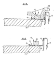
- First Component 11 is the glass pane of the window for example a passenger car. Between the Glass pane 11 and the body flange 17 should be one Aperture 9 can be held adjustable.
- Fig. 9 shows the completed arrangement of the holding part 13 and the connecting element 12 on the glass pane 11.
- a U-shaped locking bar 16 is attached on the angled flange 12b of the connecting element 12.
- Fig. 10 shows how the prepared according to Figs. 8 and 9 Glass pane 11 arranged on the body flange 17 becomes.
- the glass pane 11 connects to the body flange 17.
- the Installation adhesive 18 is arranged so that when the Glass pane 11 the flange 12c of the Connecting element 12 presses into the installation adhesive 18. After pressing the glass pane 11 onto the installation adhesive 18 and thus to the body flange 17 is in the Locking bar 16 on the flange 12 a of the connecting element 12 an aperture 9 snapped into place between Glass pane 11 and body flange 17 covered.
- the aperture 9 very much simply be aligned to point P, for example.
- the installation adhesive 18 is the other Flange 12c of the connecting element 12 in the installation adhesive firmly anchored and is at the same time that too Connecting element 12 secured against displacement, with which the position of the aperture 19 is fixed.
- FIG. 11 shows another application example of the invention Connection, namely the connection of two Components 21 and 22 with a hinge 20 Hinge straps 20a and 20b.
- the right one in the drawing Hinge band 20b has an opening 23.
- For firm connection of the hinge strap 20b to the component 22 becomes a holding block 25 which overlaps the hinge band produced, which is connected to the component 22.
- In the connection area is on the component 22 first applied an adhesive 24. Then is put on in the form, not shown, that the Envelops the end of the hinge band 20b, a potting compound 8 filled, which encloses the end of the hinge band 20b and also extends through the opening 23 and which connects with the adhesive 24 below. After this The casting compound cures and the adhesive sets the shape not shown removed and is the holding block 25 formed, the hinge band 20b with the component 22 firmly connects.
- the other hinge band 20a of the hinge 20 is with the Component 21 adjustable using the invention connected, according to the training and how they work in the first embodiment according to FIGS. 1 to 7 is described.
- the U-shaped hinge band 20a comprehensive and connected to the component 21 holding part is designated 33 here. This is under the holding part 33 Hinge band 20a of the hinge 20 in the longitudinal direction slidable. With 34 is in the holding part 33 arranged adjustable against the hinge band 20a Designated locking screw. By turning the locking screw 34 can this against the hinge band 20a are moved, whereby the hinge band 20a is determined can be, so that it is then no longer displaceable. This allows the hinge connection between the two Components 21 and 22 during assembly by moving the Hinge strap 20a and subsequent detection of the Hinge strap with the locking screw 34 exactly be aligned, i.e. the width of the gap S. to be changed.
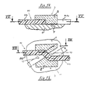
- FIGS. 12 and 13 is the connecting element 40 from a hollow cylinder 40a and a radially attached to the hollow cylinder 40a Flange 40b formed. That from the potting compound 8 by means of a molding, not shown, according to the embodiment 1 to 7 designed holding part 3rd engages over the one forming the hollow cylinder 40a Section of the connecting element 40 Holding element 3 in the of the hollow cylinder 40a enclosed interior 42 in front. The holding part 3 is there connected to the first component 1 with the adhesive 4.
- the holding part 3 is formed from the potting compound 8 is preferably by the molding, not shown in Area of the radially attached flange 40b of the Connecting element 40 formed a cavity 43. With the cavity 43 is a pivoting space for the radial attached flange 40b formed. To swivel the Flange 40b is the hollow cylinder 40a by the Holding part 3 formed, filling the interior 42 Axis of rotation rotated.
- the Connecting element 40 consists of two flat bands 41a, 41b each with a rectangular cross section, which has a Z-shaped Bend 44 are connected to each other.
- the end the potting compound 8 shaped holding part 3 overlaps Connecting element 40 in the region of the Z-shaped fold 44 and is with the first component 1 with the adhesive 4th connected.
- a is not Shown molding used.
- the molding is like this formed that in the region of the connecting element 40th Cavities 43 are formed, the rotation of the Connecting element 40 by a through the Z-shaped Folding 44 extending from the drawing level allow emerging axis of rotation.
Landscapes
- Engineering & Computer Science (AREA)
- Mechanical Engineering (AREA)
- Physical Or Chemical Processes And Apparatus (AREA)
- Lining Or Joining Of Plastics Or The Like (AREA)
- Connection Of Plates (AREA)
- Casting Or Compression Moulding Of Plastics Or The Like (AREA)
- Mutual Connection Of Rods And Tubes (AREA)
Claims (11)
- Procédé de réalisation d'une liaison réglable entre des composants, au moyen d'un élément de liaison reliant les composants, dans lequel l'élément de liaison (2) est placé sur un premier composant (1), sur au moins un côté de l'élément de liaison une colle (4) est appliquée sur le composant dans la zone de liaison avec un élément de maintien (3) à mouler, sur le composant (1) est placé un élément de moulage (5) qui passe sur la zone de liaison et sur l'élément de liaison, dans lequel par introduction d'une masse de scellement (8) dans l'élément de moulage (5), l'élément de maintien (3) qui prend appui sur la colle (4) dans la zone de liaison et qui passe librement sur l'élément de liaison (2), est moulé et dans lequel l'élément façonné (5) est enlevé après durcissement de la masse de scellement et prise de la colle.
- Procédé selon la revendication 1, caractérisé en ce que l'élément de liaison (2) est traité avec un agent de démoulage avant le moulage de l'élément de maintien (3) dans la masse de scellement (8).
- Procédé selon la revendication 1 ou 2, caractérisé en ce que la masse de scellement (8) est injectée dans l'élément de moulage (5).
- Procédé selon la revendication 3, caractérisé en ce que l'élément de moulage (5) est abaissé sur le lieu d'utilisation avec la buse d'injection de la base de scellement (8) et, après durcissement de la base de scellement, il est à nouveau relevé avec la buse d'injection.
- Liaison réglable pouvant être réalisée avec le procédé selon l'une des revendications 1 à 4, caractérisée en ce qu'elle comporte un élément de liaison (2) placé sur un premier composant (1), sur lequel passe un élément de maintien (3) en U fabriqué sur place dans la masse de scellement (8), et qui est maintenu librement par l'élément de maintien (3) sur le premier composant (1), ce qui fait que l'élément de liaison (3) peut coulisser entre le premier composant (1) et l'élément de maintien (3).
- Liaison selon la revendication 5, caractérisée en ce que l'élément de liaison (2) est réalisé sous la forme d'une bande plate de section transversale rectangulaire et en ce que les extrémités de l'élément de liaison présentent des brides (2b, 2c) repliées à angle droit.
- Liaison réglable pouvant être réalisée avec le procédé selon l'une des revendications 1 à 4, caractérisée en ce qu'elle comporte un élément de liaison (40) placé sur un premier composant (1), sur lequel passe par endroits un élément de maintien (3) fabriqué sur place dans la masse de scellement (8), et qui est maintenu librement par l'élément de maintien (3) sur le premier composant (1), ce qui fait que l'élément de liaison (40) peut tourner entre le premier composant (1) et l'élément de maintien (3).
- Liaison selon la revendication 7, caractérisée en ce que l'élément de liaison (40) est constitué d'un cylindre creux (40a) et d'une bride (40b) placée radialement sur le cylindre creux (40a).
- Liaison selon la revendication 7, caractérisée en ce que l'élément de liaison (40) est constitué de deux bandes plates (41a, 41b), reliées entre elles par une pliure en Z (44) et de section transversale rectangulaire.
- Liaison selon l'une des revendications 5 à 9, caractérisée en ce qu'elle comporte un dispositif de blocage pour le blocage de l'élément de liaison (2, 40).
- Liaison selon la revendication 10, caractérisée en ce qu'une vis de blocage (34), déplaçable par rapport à l'élément de liaison (2, 40), est disposée dans l'élément de maintien (3).
Applications Claiming Priority (4)
| Application Number | Priority Date | Filing Date | Title |
|---|---|---|---|
| DE19717934 | 1997-04-29 | ||
| DE19717934 | 1997-04-29 | ||
| DE19748831A DE19748831A1 (de) | 1997-04-29 | 1997-11-05 | Verfahren und Vorrichtung zum Herstellen einer verstellbaren Verbindung zwischen Bauteilen, mit einem die Bauteile verbindenden Verbindungselement |
| DE19748831 | 1997-11-05 |
Publications (3)
| Publication Number | Publication Date |
|---|---|
| EP0875352A2 EP0875352A2 (fr) | 1998-11-04 |
| EP0875352A3 EP0875352A3 (fr) | 1998-11-11 |
| EP0875352B1 true EP0875352B1 (fr) | 2000-06-07 |
Family
ID=26036152
Family Applications (1)
| Application Number | Title | Priority Date | Filing Date |
|---|---|---|---|
| EP98105930A Expired - Lifetime EP0875352B1 (fr) | 1997-04-29 | 1998-04-01 | Procédé et appareil pour produire une liaison ajustable entre des pièces, avec un élément de connection connectant les pièces |
Country Status (2)
| Country | Link |
|---|---|
| EP (1) | EP0875352B1 (fr) |
| ES (1) | ES2149028T3 (fr) |
Families Citing this family (1)
| Publication number | Priority date | Publication date | Assignee | Title |
|---|---|---|---|---|
| DE10322637A1 (de) * | 2003-05-20 | 2004-12-09 | Henniges Elastomer- Und Kunststofftechnik Gmbh & Co Kg | Verfahren zur Befestigung eines Funktionselementes, insbesondere einer Dichtung, an einer Glasscheibe einer Fahrzeugverglasung |
Family Cites Families (5)
| Publication number | Priority date | Publication date | Assignee | Title |
|---|---|---|---|---|
| IT1010031B (it) * | 1973-04-25 | 1977-01-10 | Saint Gobain | Procedimento per il montaggio di guarnizioni in particolare a cer niera su pannelli in particolare di vetro e guarnizione a cerniera predisposte per l esecuzione del procedimento |
| FR2641311B1 (fr) * | 1988-12-30 | 1991-04-19 | Kester Ste Civile | Charniere apparente pour ameublement |
| DE4304209A1 (de) * | 1993-02-12 | 1994-08-18 | Henniges Elastomer Kunststoff | Ausstellbares Karosseriefenster für Kraftfahrzeuge |
| US5522636A (en) * | 1994-10-05 | 1996-06-04 | Ford Motor Company | Method and apparatus for adjustably positioning window assemblies in automotive vehicles |
| JPH09100670A (ja) * | 1995-10-06 | 1997-04-15 | Shinkansai Bearing Kk | ドアヒンジおよびドアヒンジ用の調整具 |
-
1998
- 1998-04-01 ES ES98105930T patent/ES2149028T3/es not_active Expired - Lifetime
- 1998-04-01 EP EP98105930A patent/EP0875352B1/fr not_active Expired - Lifetime
Also Published As
| Publication number | Publication date |
|---|---|
| EP0875352A2 (fr) | 1998-11-04 |
| ES2149028T3 (es) | 2000-10-16 |
| EP0875352A3 (fr) | 1998-11-11 |
Similar Documents
| Publication | Publication Date | Title |
|---|---|---|
| DE3811427C2 (fr) | ||
| DE19929057B4 (de) | Fahrzeugtragstruktur und Verfahren zu deren Herstellung | |
| EP0671985A1 (fr) | Outil de pressage. | |
| DE3147939A1 (de) | Form und verfahren zum herstellen von speichenraedern | |
| DE3340634A1 (de) | Verfahren und vorrichtung zum vorab- und/oder endgueltigen anschlagen einer fahrzeugtuer | |
| EP4594074A1 (fr) | Élément latéral en plastique creux et procédé de production d'un tel élément latéral en plastique creux | |
| EP1920899A1 (fr) | Procédé destiné à la fabrication de composants hybrides en matière synthétique, outil correspondant et utilisation d'un tel outil | |
| EP0870933B1 (fr) | Dispositif et procédé pour réaliser une connection entre deux éléments | |
| DE3347503A1 (de) | Selbstsichernder sperrbolzen | |
| EP1554099A1 (fr) | Procede pour la production d'un papillon dans un boitier de papillon traversant | |
| DE19730560A1 (de) | Verfahren zum Herstellen einer Klebeverbindung | |
| DE1806665C3 (de) | Verfahren und Vorrichtung zum Befestigen von Muffen aus Metall an gerippten Bewehrungsstäben und nach dem Verfahren hergestellte Stoßverbindung | |
| WO2009068129A1 (fr) | Structure porteuse et procédé de fabrication | |
| EP0875352A2 (fr) | Procédé et appareil pour produire une liaison ajustable entre des pièces, avec un élément de connection connectant les pièces | |
| DE19748831A1 (de) | Verfahren und Vorrichtung zum Herstellen einer verstellbaren Verbindung zwischen Bauteilen, mit einem die Bauteile verbindenden Verbindungselement | |
| DE102010028294A1 (de) | Positionierungsvorrichtung und Verfahren zur Herstellung einer Bauteilanordnung | |
| DE19906758A1 (de) | Fenster- und Türflügelbeschlag und Verfahren zu dessen Herstellung | |
| DE3322572A1 (de) | Verfahren und vorrichtung zum bogenfoermigen umformen eines aus einem thermoplastischen kunststoff bestehenden profilstrangabschnittes mit hohlkammern | |
| WO1999049986A1 (fr) | Profile en matiere plastique pour etancheifier un interstice entre deux elements de carrosserie de vehicules | |
| EP3460161B1 (fr) | Procédé et dispositif de raccord destiné à raccorder un jambage à un profilé de cadre d'une fenêtre ou d'une porte en matière plastique | |
| DE10326609B4 (de) | Hohlprofil und Verfahren zur Herstellung eines Hohlprofils | |
| EP4146459A1 (fr) | Procédé de fabrication d'un élément de renforcement | |
| EP4069577A1 (fr) | Cloison | |
| DE2814433A1 (de) | Verbesserungen zur herstellung eines kugelgelenkes zur verbindung von zwei roehren | |
| EP0610691A1 (fr) | Fenêtre ouvrante de carrosserie pour véhicules à moteur |
Legal Events
| Date | Code | Title | Description |
|---|---|---|---|
| PUAI | Public reference made under article 153(3) epc to a published international application that has entered the european phase |
Free format text: ORIGINAL CODE: 0009012 |
|
| PUAL | Search report despatched |
Free format text: ORIGINAL CODE: 0009013 |
|
| AK | Designated contracting states |
Kind code of ref document: A2 Designated state(s): DE ES FR GB IT |
|
| AX | Request for extension of the european patent |
Free format text: AL;LT;LV;MK;RO;SI |
|
| AK | Designated contracting states |
Kind code of ref document: A3 Designated state(s): AT BE CH CY DE DK ES FI FR GB GR IE IT LI LU MC NL PT SE |
|
| AX | Request for extension of the european patent |
Free format text: AL;LT;LV;MK;RO;SI |
|
| 17P | Request for examination filed |
Effective date: 19990408 |
|
| AKX | Designation fees paid |
Free format text: DE ES FR GB IT |
|
| GRAG | Despatch of communication of intention to grant |
Free format text: ORIGINAL CODE: EPIDOS AGRA |
|
| 17Q | First examination report despatched |
Effective date: 19990827 |
|
| GRAG | Despatch of communication of intention to grant |
Free format text: ORIGINAL CODE: EPIDOS AGRA |
|
| GRAH | Despatch of communication of intention to grant a patent |
Free format text: ORIGINAL CODE: EPIDOS IGRA |
|
| GRAH | Despatch of communication of intention to grant a patent |
Free format text: ORIGINAL CODE: EPIDOS IGRA |
|
| GRAA | (expected) grant |
Free format text: ORIGINAL CODE: 0009210 |
|
| AK | Designated contracting states |
Kind code of ref document: B1 Designated state(s): DE ES FR GB IT |
|
| REF | Corresponds to: |
Ref document number: 59800170 Country of ref document: DE Date of ref document: 20000713 |
|
| ITF | It: translation for a ep patent filed | ||
| ET | Fr: translation filed | ||
| GBT | Gb: translation of ep patent filed (gb section 77(6)(a)/1977) |
Effective date: 20000907 |
|
| REG | Reference to a national code |
Ref country code: ES Ref legal event code: FG2A Ref document number: 2149028 Country of ref document: ES Kind code of ref document: T3 |
|
| PLBE | No opposition filed within time limit |
Free format text: ORIGINAL CODE: 0009261 |
|
| STAA | Information on the status of an ep patent application or granted ep patent |
Free format text: STATUS: NO OPPOSITION FILED WITHIN TIME LIMIT |
|
| 26N | No opposition filed | ||
| REG | Reference to a national code |
Ref country code: GB Ref legal event code: IF02 |
|
| PGFP | Annual fee paid to national office [announced via postgrant information from national office to epo] |
Ref country code: DE Payment date: 20050308 Year of fee payment: 8 |
|
| PGFP | Annual fee paid to national office [announced via postgrant information from national office to epo] |
Ref country code: GB Payment date: 20050321 Year of fee payment: 8 |
|
| PGFP | Annual fee paid to national office [announced via postgrant information from national office to epo] |
Ref country code: FR Payment date: 20050419 Year of fee payment: 8 |
|
| PGFP | Annual fee paid to national office [announced via postgrant information from national office to epo] |
Ref country code: ES Payment date: 20050421 Year of fee payment: 8 |
|
| PG25 | Lapsed in a contracting state [announced via postgrant information from national office to epo] |
Ref country code: GB Free format text: LAPSE BECAUSE OF NON-PAYMENT OF DUE FEES Effective date: 20060401 |
|
| PG25 | Lapsed in a contracting state [announced via postgrant information from national office to epo] |
Ref country code: ES Free format text: LAPSE BECAUSE OF NON-PAYMENT OF DUE FEES Effective date: 20060403 |
|
| PGFP | Annual fee paid to national office [announced via postgrant information from national office to epo] |
Ref country code: IT Payment date: 20060430 Year of fee payment: 9 |
|
| PG25 | Lapsed in a contracting state [announced via postgrant information from national office to epo] |
Ref country code: DE Free format text: LAPSE BECAUSE OF NON-PAYMENT OF DUE FEES Effective date: 20061101 |
|
| GBPC | Gb: european patent ceased through non-payment of renewal fee |
Effective date: 20060401 |
|
| REG | Reference to a national code |
Ref country code: FR Ref legal event code: ST Effective date: 20061230 |
|
| REG | Reference to a national code |
Ref country code: ES Ref legal event code: FD2A Effective date: 20060403 |
|
| PG25 | Lapsed in a contracting state [announced via postgrant information from national office to epo] |
Ref country code: FR Free format text: LAPSE BECAUSE OF NON-PAYMENT OF DUE FEES Effective date: 20060502 |
|
| PG25 | Lapsed in a contracting state [announced via postgrant information from national office to epo] |
Ref country code: IT Free format text: LAPSE BECAUSE OF NON-PAYMENT OF DUE FEES Effective date: 20070401 |