EP0875359A2 - Anlage zur Herstellung einer orientierten Folie und Verfahren zum Messen der Doppelbrechung - Google Patents
Anlage zur Herstellung einer orientierten Folie und Verfahren zum Messen der Doppelbrechung Download PDFInfo
- Publication number
- EP0875359A2 EP0875359A2 EP98107950A EP98107950A EP0875359A2 EP 0875359 A2 EP0875359 A2 EP 0875359A2 EP 98107950 A EP98107950 A EP 98107950A EP 98107950 A EP98107950 A EP 98107950A EP 0875359 A2 EP0875359 A2 EP 0875359A2
- Authority
- EP
- European Patent Office
- Prior art keywords
- film
- extremum
- thickness
- wavelength
- orientation
- Prior art date
- Legal status (The legal status is an assumption and is not a legal conclusion. Google has not performed a legal analysis and makes no representation as to the accuracy of the status listed.)
- Withdrawn
Links
Images


Classifications
-
- G—PHYSICS
- G01—MEASURING; TESTING
- G01N—INVESTIGATING OR ANALYSING MATERIALS BY DETERMINING THEIR CHEMICAL OR PHYSICAL PROPERTIES
- G01N21/00—Investigating or analysing materials by the use of optical means, i.e. using sub-millimetre waves, infrared, visible or ultraviolet light
- G01N21/17—Systems in which incident light is modified in accordance with the properties of the material investigated
- G01N21/21—Polarisation-affecting properties
- G01N21/23—Bi-refringence
-
- B—PERFORMING OPERATIONS; TRANSPORTING
- B29—WORKING OF PLASTICS; WORKING OF SUBSTANCES IN A PLASTIC STATE IN GENERAL
- B29C—SHAPING OR JOINING OF PLASTICS; SHAPING OF MATERIAL IN A PLASTIC STATE, NOT OTHERWISE PROVIDED FOR; AFTER-TREATMENT OF THE SHAPED PRODUCTS, e.g. REPAIRING
- B29C48/00—Extrusion moulding, i.e. expressing the moulding material through a die or nozzle which imparts the desired form; Apparatus therefor
- B29C48/03—Extrusion moulding, i.e. expressing the moulding material through a die or nozzle which imparts the desired form; Apparatus therefor characterised by the shape of the extruded material at extrusion
- B29C48/07—Flat, e.g. panels
- B29C48/08—Flat, e.g. panels flexible, e.g. films
-
- B—PERFORMING OPERATIONS; TRANSPORTING
- B29—WORKING OF PLASTICS; WORKING OF SUBSTANCES IN A PLASTIC STATE IN GENERAL
- B29C—SHAPING OR JOINING OF PLASTICS; SHAPING OF MATERIAL IN A PLASTIC STATE, NOT OTHERWISE PROVIDED FOR; AFTER-TREATMENT OF THE SHAPED PRODUCTS, e.g. REPAIRING
- B29C48/00—Extrusion moulding, i.e. expressing the moulding material through a die or nozzle which imparts the desired form; Apparatus therefor
- B29C48/25—Component parts, details or accessories; Auxiliary operations
- B29C48/92—Measuring, controlling or regulating
-
- B—PERFORMING OPERATIONS; TRANSPORTING
- B29—WORKING OF PLASTICS; WORKING OF SUBSTANCES IN A PLASTIC STATE IN GENERAL
- B29C—SHAPING OR JOINING OF PLASTICS; SHAPING OF MATERIAL IN A PLASTIC STATE, NOT OTHERWISE PROVIDED FOR; AFTER-TREATMENT OF THE SHAPED PRODUCTS, e.g. REPAIRING
- B29C55/00—Shaping by stretching, e.g. drawing through a die; Apparatus therefor
- B29C55/02—Shaping by stretching, e.g. drawing through a die; Apparatus therefor of plates or sheets
- B29C55/10—Shaping by stretching, e.g. drawing through a die; Apparatus therefor of plates or sheets multiaxial
- B29C55/12—Shaping by stretching, e.g. drawing through a die; Apparatus therefor of plates or sheets multiaxial biaxial
- B29C55/14—Shaping by stretching, e.g. drawing through a die; Apparatus therefor of plates or sheets multiaxial biaxial successively
- B29C55/143—Shaping by stretching, e.g. drawing through a die; Apparatus therefor of plates or sheets multiaxial biaxial successively firstly parallel to the direction of feed and then transversely thereto
-
- B—PERFORMING OPERATIONS; TRANSPORTING
- B29—WORKING OF PLASTICS; WORKING OF SUBSTANCES IN A PLASTIC STATE IN GENERAL
- B29C—SHAPING OR JOINING OF PLASTICS; SHAPING OF MATERIAL IN A PLASTIC STATE, NOT OTHERWISE PROVIDED FOR; AFTER-TREATMENT OF THE SHAPED PRODUCTS, e.g. REPAIRING
- B29C37/00—Component parts, details, accessories or auxiliary operations, not covered by group B29C33/00 or B29C35/00
- B29C2037/90—Measuring, controlling or regulating
-
- B—PERFORMING OPERATIONS; TRANSPORTING
- B29—WORKING OF PLASTICS; WORKING OF SUBSTANCES IN A PLASTIC STATE IN GENERAL
- B29C—SHAPING OR JOINING OF PLASTICS; SHAPING OF MATERIAL IN A PLASTIC STATE, NOT OTHERWISE PROVIDED FOR; AFTER-TREATMENT OF THE SHAPED PRODUCTS, e.g. REPAIRING
- B29C2948/00—Indexing scheme relating to extrusion moulding
- B29C2948/92—Measuring, controlling or regulating
- B29C2948/92009—Measured parameter
- B29C2948/92114—Dimensions
- B29C2948/92152—Thickness
-
- B—PERFORMING OPERATIONS; TRANSPORTING
- B29—WORKING OF PLASTICS; WORKING OF SUBSTANCES IN A PLASTIC STATE IN GENERAL
- B29C—SHAPING OR JOINING OF PLASTICS; SHAPING OF MATERIAL IN A PLASTIC STATE, NOT OTHERWISE PROVIDED FOR; AFTER-TREATMENT OF THE SHAPED PRODUCTS, e.g. REPAIRING
- B29C2948/00—Indexing scheme relating to extrusion moulding
- B29C2948/92—Measuring, controlling or regulating
- B29C2948/92323—Location or phase of measurement
- B29C2948/92438—Conveying, transporting or storage of articles
-
- B—PERFORMING OPERATIONS; TRANSPORTING
- B29—WORKING OF PLASTICS; WORKING OF SUBSTANCES IN A PLASTIC STATE IN GENERAL
- B29C—SHAPING OR JOINING OF PLASTICS; SHAPING OF MATERIAL IN A PLASTIC STATE, NOT OTHERWISE PROVIDED FOR; AFTER-TREATMENT OF THE SHAPED PRODUCTS, e.g. REPAIRING
- B29C2948/00—Indexing scheme relating to extrusion moulding
- B29C2948/92—Measuring, controlling or regulating
- B29C2948/92504—Controlled parameter
- B29C2948/9258—Velocity
- B29C2948/9259—Angular velocity
-
- B—PERFORMING OPERATIONS; TRANSPORTING
- B29—WORKING OF PLASTICS; WORKING OF SUBSTANCES IN A PLASTIC STATE IN GENERAL
- B29C—SHAPING OR JOINING OF PLASTICS; SHAPING OF MATERIAL IN A PLASTIC STATE, NOT OTHERWISE PROVIDED FOR; AFTER-TREATMENT OF THE SHAPED PRODUCTS, e.g. REPAIRING
- B29C2948/00—Indexing scheme relating to extrusion moulding
- B29C2948/92—Measuring, controlling or regulating
- B29C2948/92504—Controlled parameter
- B29C2948/92609—Dimensions
- B29C2948/92647—Thickness
-
- B—PERFORMING OPERATIONS; TRANSPORTING
- B29—WORKING OF PLASTICS; WORKING OF SUBSTANCES IN A PLASTIC STATE IN GENERAL
- B29C—SHAPING OR JOINING OF PLASTICS; SHAPING OF MATERIAL IN A PLASTIC STATE, NOT OTHERWISE PROVIDED FOR; AFTER-TREATMENT OF THE SHAPED PRODUCTS, e.g. REPAIRING
- B29C2948/00—Indexing scheme relating to extrusion moulding
- B29C2948/92—Measuring, controlling or regulating
- B29C2948/92504—Controlled parameter
- B29C2948/92704—Temperature
-
- B—PERFORMING OPERATIONS; TRANSPORTING
- B29—WORKING OF PLASTICS; WORKING OF SUBSTANCES IN A PLASTIC STATE IN GENERAL
- B29C—SHAPING OR JOINING OF PLASTICS; SHAPING OF MATERIAL IN A PLASTIC STATE, NOT OTHERWISE PROVIDED FOR; AFTER-TREATMENT OF THE SHAPED PRODUCTS, e.g. REPAIRING
- B29C2948/00—Indexing scheme relating to extrusion moulding
- B29C2948/92—Measuring, controlling or regulating
- B29C2948/92819—Location or phase of control
- B29C2948/92857—Extrusion unit
- B29C2948/92876—Feeding, melting, plasticising or pumping zones, e.g. the melt itself
- B29C2948/92885—Screw or gear
-
- B—PERFORMING OPERATIONS; TRANSPORTING
- B29—WORKING OF PLASTICS; WORKING OF SUBSTANCES IN A PLASTIC STATE IN GENERAL
- B29C—SHAPING OR JOINING OF PLASTICS; SHAPING OF MATERIAL IN A PLASTIC STATE, NOT OTHERWISE PROVIDED FOR; AFTER-TREATMENT OF THE SHAPED PRODUCTS, e.g. REPAIRING
- B29C2948/00—Indexing scheme relating to extrusion moulding
- B29C2948/92—Measuring, controlling or regulating
- B29C2948/92819—Location or phase of control
- B29C2948/92857—Extrusion unit
- B29C2948/92904—Die; Nozzle zone
-
- B—PERFORMING OPERATIONS; TRANSPORTING
- B29—WORKING OF PLASTICS; WORKING OF SUBSTANCES IN A PLASTIC STATE IN GENERAL
- B29C—SHAPING OR JOINING OF PLASTICS; SHAPING OF MATERIAL IN A PLASTIC STATE, NOT OTHERWISE PROVIDED FOR; AFTER-TREATMENT OF THE SHAPED PRODUCTS, e.g. REPAIRING
- B29C2948/00—Indexing scheme relating to extrusion moulding
- B29C2948/92—Measuring, controlling or regulating
- B29C2948/92819—Location or phase of control
- B29C2948/92933—Conveying, transporting or storage of articles
Definitions
- the present invention relates to a drawing system in which a thermoplastic resin such as polypropylene, polyethylene or the like is molded into a shape of a film through a die by melt-extrusion with an extruder, a not-oriented film thus molded is drawn at a temperature equal to or lower than a melting point in longitudinal and lateral directions to orient molecules, and to an oriented film producing facility which comprises the drawing system, a measuring apparatus for measuring a thickness and an degree of orientation of a drawn film, and in which facility a predetermined control operation is performed on the drawing system based on measured values.
- a thermoplastic resin such as polypropylene, polyethylene or the like
- the present invention further relates to a high speed measuring method for measuring a birefringence, especially a birefringence, whose retardation which is larger than a measuring wavelength.
- a film used for packaging and the like has conventionally been produced in such a manner that a not-oriented film which is already molded into a shape of a thin film through die mounted on an extruder is subjected to drawing in longitudinal and lateral directions to orient molecules, whereby a bi-axially oriented film, whose mechanical characteristic, especially a strength is improved, made of polypropylene, vinylidene chloride resin, vinyl chloride resin, polystyrene, polyethylene terephthalate, polyethylene naphthalate, polyethylene, polyamide or the like is produced.
- the not-oriented film to be bi-axially oriented and the like are categorized in a crystalline resin and an amorphous resin and in the case of the crystalline rein, a film is extruded at a temperature equal to or higher than a melting point and subjected to a rapid cooling while an amorphous condition is maintained in order to facilitate orientation. Then, the not-oriented film is drawn at a temperature equal to or lower than a melting point for orientation.
- a film is extruded by an extruder at a temperature higher than a glass transition temperature so as to give the maximum degree of transparency.
- the not-oriented film is cooled to a temperature in an elasticity range and drawn at the temperature for orientation.
- a drawing machine which is used for orientation of a not-oriented film is, in a broad sense, categorized in a sequential bi-axial drawing type in which a longitudinal drawing is followed by a lateral drawing and a simultaneous bi-axial drawing type in which longitudinal and lateral drawings are simultaneously conducted. These two type machines are desired that a film which is oriented in a uniform manner in the two directions can be produced.
- sequential drawing while drawings are conducted in two stages, it is desirable that draw ratios of longitudinal and lateral directions and a temperature in respective stages can independently be changed in order to improve controllability on an degree of orientation and that the draw ratios can independently be changed in simultaneous drawing as well.
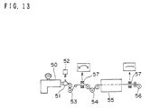
- a measuring apparatus for measuring a film thickness included in a drawing system and a film automatic control apparatus by which an extruder and a die are subjected to a predetermined control while a thickness is measured by the measuring apparatus.
- the film automatic thickness control apparatus comprises: an extruder 50 which enables adjustment of a rotation number of a screw thereof, a die 51 mounted to the extruder, a die adjusting apparatus 52 for adjusting an opening degree of an extrusion mouth, a base film shaping apparatus 53 in which a not-oriented film is cooled to be hard, drawing machines 54, 55 which draws the not-oriented film which has been cooled to be hard is drawn in longitudinal and lateral directions, and a take-up apparatus 56 which takes up a drawn film, and ⁇ ray thickness gauges 57, 57 for measuring a thickness are respectively deployed at positions upstream of the longitudinal drawing machine 54 and downstream of a lateral drawing machine 55.
- a thickness of a film is measured by these gauges 57, 57 and not only is a screw rotational number of the extruder 50 controlled based on a measuring data but an opening degree of the die 51 is controlled by an adjust bolt or the like.
- birefringence As one of the means for evaluating a degree of orientation in an oriented high polymer film.
- a retardation caused by a birefringence is larger than a measuring wavelength, a birefringence has to be computed from a spectrum of transmitted light when a high polymer film which is a specimen showing a birefringence is placed between a polarizing elements and therefore, as a high speed measuring method for measuring a birefringence, there has been known a method in which data of transmitted light spectrum measured by a multi-channel spectrometer are analyzed by use of a data processor such as a computer.
- a thickness in a width direction can be controlled, but it entails reduction of a mass per a unit time of a not-oriented film during a time when the die extrusion mouth is narrowed, which is not to maintain a uniform degree of orientation over all the surface area.
- the present invention has been made as improvement in light of the above mentioned problems.
- the present invention have objects to seek to achieve that a thickness and degree of orientation of a drawn film are maintained constant at a high speed, and that there is provided a drawing system, in which there is shortened a time elapsed from a time when a molding material is input to an extruder to a time when a film is drawn and taken-up in a take-up apparatus, and with which a high quality film or the like is produced at a high speed.
- the present invention has an object to seek to achieve that there is provided a drawing system which has a reduced probability at which a film, whether drawn or not, or the like, is broken down in a drawing operation.
- the present invention has adopted the following means to achieve the objects:
- An oriented film producing facility comprises: a facility for melting a molding material; an extruder having a die for shaping the molding material to a not-oriented film; a base film molding apparatus for producing a base film by cooling the not-oriented film shaped through the die; a longitudinal drawing machine for drawing the cooled base film in a longitudinal direction with a low speed roll and a high speed roll; and a lateral drawing machine for drawing the longitudinally drawn film in a lateral direction by holding both ends of the longitudinally drawn film.
- the oriented film producing facility further comprises: a thickness gauge for measuring a thickness of the longitudinally drawn film in real time after the cooled base film is drawn in the longitudinal direction and an film orientation measuring apparatus for measuring an degree of orientation of the longitudinally drawn film in real time after the cooled base film is drawn in the longitudinal direction, wherein a signal corresponding to a thickness measured by the thickness gauge is output to a computer, a signal corresponding to an degree of orientation measured by a orientation measuring apparatus is output to the computer, the computer comprising a thickness comparison operation to compare a preset thickness with the measured thickness and an orientation comparison operation to compare a preset degree of orientation with the measured degree of orientation, and a control signal to change a longitudinal draw ratio in longitudinal drawing is output based on results of the respective comparison operations so as to coincide with a preset target value and a drawing condition is controlled in accordance with the control signal.
- a thickness and degree of orientation of a film after a longitudinal drawing and a lateral drawing or independently measured in a continuous manner by a thickness gauge and an film orientation measuring apparatus, and measured values are input to a computer.
- the computer which has been input with the measured values compares preset values with the respective measured values of a thickness and an degree of orientation and performs a control operation to change a longitudinal draw ratio if the measured values are different from the respective preset values based on comparative results.
- a thickness of a film after longitudinal drawing can be controlled, a thickness and degree of orientation may be measured at any positions on the film and can be measured during the longitudinal drawing.
- a computer stores preset target values of a thickness as a profile in its memory, wherein the profile of thickness means a distribution of thickness in a width direction (lateral direction).
- a change in a longitudinal draw ratio is realized by a control operation of slowing or accelerating a rotational speed or speeds of a low speed roll or/and a high speed roll.
- Control of a rotational speed can be attained by slowing a low speed roll singly, accelerating a high speed roll singly, slowing the low speed and accelerating the high speed roll, or slowing or accelerating both speeds in a proportional manner.
- a rotational speed control of these rolls can be achieved by adjusting a rotational speed of a motor responsible for rotational drive of each roll.
- a change is achieved by adjusting a draw gap between a low speed roll and a high speed roll or adjusting a draw angle of these rolls is available.
- the draw gap or draw angle is adjusted by displacing only a low speed roll in a direction, upward or downward, or leftward or rightward, or displacing only a high speed roll in a direction, upward or downward, or leftward or rightward.
- both rolls may be displaced in a direction, upward or downward, and a direction, leftward or rightward. Movements of the rolls can be achieved such that a servo motor or the like is equipped to a roll displacement mechanism and the roll displacement mechanism is driven by rotation of the motor.
- a longitudinal draw ratio can alternately be adjusted by adjusting pressing force of the cooled base film acting upon the high speed roll and the low speed roll.
- an air conditioner which sucks or jets air is provided in the vicinity of a contact position of the film to any or both of a high speed roll and low speed roll, and air is jet to reduce a press-bonding strength if the strength is large or air is sucked to increase a press-bonding strength if the strength is small.
- a cold air is jet if a press-bonding strength is large, or hot air is jet or a flame is shot if a press-bonding strength is small.
- a plurality of nozzles are desirably provided to one roll.
- the thickness gauge for measuring a thickness of the longitudinally drawn film measures the thickness of the longitudinally drawn film on respective divided regions of the longitudinally drawn film along the lateral direction thereof after the longitudinal drawing and the orientation measuring apparatus measures the degree of orientation of the longitudinally drawn film on respective divided regions of the longitudinally drawn film along the lateral direction thereof after the longitudinal drawing.
- a control operation to change a longitudinal draw ratio is conducted so that thicknesses and degree of orientations in the respective blocks coincide with the respective target values. While a thickness and degree of orientation are measured by dividing a width of the film in a lateral direction into some regions, it is also possible that a film is divided into squares like those on a checkerboard by setting constant distances between adjacent boundaries in longitudinal and lateral directions on the film or regions at a constant distance between boundaries in a longitudinal direction only.
- An oriented film producing facility comprises: a facility for melting a molding material; an extruder having a die for shaping the molding material to a not-oriented film; a base film molding apparatus for producing a base film by cooling a not-oriented film shaped through the die; a longitudinal drawing machine for drawing the cooled base film in a longitudinal direction with a low speed roll and a high speed roll; and a lateral drawing machine for drawing the longitudinally drawn film in a lateral direction by holding both ends of the longitudinally drawn film.
- the oriented film producing facility further comprises: a thickness gauge for measuring a thickness of the laterally drawn film in real time after the longitudinally drawn film is drawn in a lateral direction and an film orientation measuring apparatus for measuring an degree of orientation of the laterally drawn film in real time after the longitudinally drawn film is drawn in the lateral direction, wherein a signal corresponding to a thickness measured by the thickness gauge is output to a computer, a signal corresponding to an degree of orientation measured by the orientation measuring apparatus is output to the computer, the computer comprising a thickness comparison operation to compare a preset thickness with the measured thickness and an orientation comparison operation to compare a preset degree of orientation and the measured degree of orientation, and a control signal to change a lateral draw ratio in lateral drawing is output based on results of the respective comparison operations so as to coincide with a preset target value and a drawing condition is controlled in accordance with the control signal.
- a thickness gauge for measuring a thickness of the laterally drawn film in real time after the longitudinally drawn film is drawn in a lateral direction
- a thickness and degree of orientation of a film after each of a longitudinal drawing and a lateral drawing are independently measured in a continuous manner by a thickness gauge and an film orientation measuring apparatus and measured values are input to a computer.
- the computer which has been input with the measured values compares preset values with the respective values of a thickness and an degree of orientation and performs a control operation to change a longitudinal draw ratio if the measured values are different from the respective preset values based on comparative results.
- the change in lateral draw ratio is achieved by adjusting a lateral draw angle in the lateral drawing.
- adjustment in a lateral draw angle is performed by adjusting only a leftward lateral draw angle if only a value of the leftward angle is different from a target value, or by adjusting only a rightward lateral draw angle if only a rightward value of the angle is different from a target value. Both draw angles, leftward and rightward, are simultaneously adjusted if both draw angles are respectively different from targets values.
- Adjustment in draw angle can be achieved such that a servo motor or the like is equipped to an angle adjustment mechanism and the motor is rotated and the mechanism is driven by the rotation.
- lateral draw ratios As another means for changing a lateral draw ratio, lateral draw ratios, left side and right side, are precisely adjusted.
- the adjustment in lateral draw speed is achieved by adjusting a rotational speed of a motor, which drives running rails to which a clip holding both ends of a film is fixedly mounted, for the purpose to adjust a magnitude of a moving speed of the clip.
- the thickness gauge for measuring a thickness of the laterally drawn film measures the thickness by dividing the laterally drawn film after the lateral drawing into regions along a lateral direction and the film orientation measuring apparatus measures the degree of orientation by dividing the laterally drawn film after the lateral drawing into regions along the lateral direction.
- a control operation to change a longitudinal draw ratio is conducted so that thicknesses and degree of orientations in the respective blocks coincide with the respective target values. While a thickness and degree of orientation are measured by dividing a width of the film in a lateral direction into regions, it is also possible that a film is divided into squares like those on a checkerboard by setting constant distances between adjacent boundaries in longitudinal and lateral directions on the film or regions at a constant distance between boundaries in a longitudinal direction only.
- the oriented film producing facility has a function that, by the control signal, a heating temperature of the longitudinally drawn film is adjusted in correspondence to blocks of a heating apparatus for heating the longitudinally drawn film in the lateral drawing, the blocks being formed by dividing the heating apparatus in a predetermined manner.
- An oriented film producing facility comprises: a facility for melting a molding material; an extruder having a die for shaping the molding material to a not-oriented film; a base film molding apparatus for producing a base film by cooling the not-oriented film shaped through the die; a longitudinal drawing machine for drawing the cooled base film in a longitudinal direction with a low speed roll and a high speed roll; and a lateral drawing machine for drawing the longitudinally drawn film in a lateral direction by holding both ends of the longitudinally drawn film.
- a heating apparatus for the longitudinally drawn film in lateral drawing is divided into predetermined blocks, the thickness of the portion of the film corresponding to each of the blocks is measured by the thickness gauge in real time and the degree of orientation of the portion of the film corresponding to each of the blocks is measured in real time by the film orientation measuring apparatus, a signal corresponding to the thickness measured by the thickness gauge is output to the computer, a signal corresponding to an degree of orientation measured by the orientation measuring apparatus is output to the computer, the computer comprising a thickness comparison operation to compare a preset thickness of each block with the measured thickness of the block and an orientation comparison operation to compare a preset degree of orientation of each block and the measured degree of orientation of the block, and a control signal for each block is output based on respective results of the respective comparison operations so as to coincide with a preset target value and a drawing condition is controlled in accordance with the control signal.
- the oriented film producing facility has a function to a heating temperature of each block is controlled in accordance with the control signal output for each block.
- a heating area of a heating apparatus for heating a film in lateral drawing is divided at a predetermined distance between adjacent boundaries and a temperature is controlled in each heating region.
- An oriented film producing facility has a function to adjust an opening degree of the die lips in accordance with the control signal.
- a magnitude of an opening degree is controlled in operation if a measured thickness and degree of orientation are different from respective preset values.
- a magnitude of an opening degree of die lips are adjusted by an adjust bolt such as a heat bolt or the like and a local adjustment of the opening degree of a die lips is conducted by a plurality of heat bolts positioned along the directions, leftward and rightward, of the die lips.
- An oriented film producing facility has a function to adjust a screw speed of the extruder in the case where a screw is equipped in the extruder in accordance with the control signal.
- a rotational speed of the screw inserted inside of the extruder is controlled in operation if a measured thickness and degree of orientation are different from respective preset values.
- a rotational speed of a screw is controlled by adjustment of a rotational speed of a motor responsible for rotational drive of the screw.
- An oriented film producing facility is a facility in which the thickness gauge measures the thickness of a film by use of near-infrared absorption and a detective function of the thickness gauge outputs a signal corresponding to a thickness in 50 m sec, and the film orientation measuring apparatus measures a birefringence based on a principle for measuring a transmitted light spectrum of a film sandwiched by polarizing elements and measures data corresponding to the birefringence in 50 m sec to output a signal showing the data measured.
- An oriented film producing facility uses the following the steps of: melting a molding material; extruding a not-oriented film by shaping the molding material with a die; molding a base film by cooling a not-oriented film shaped through the die; longitudinally drawing the cooled base film with a low speed roll and a high speed roll; laterally drawing the longitudinally drawn film by holding both ends; measuring a thickness of the longitudinally drawn film in real time after longitudinal drawing; measuring an degree of orientation of the laterally drawn film in real time after lateral drawing; outputting a signal corresponding to a thickness measured by the thickness measuring step to a computing step; outputting a signal corresponding to an degree of orientation measured by the degree of orientation measuring step to the computing step; comparing the preset thickness with the measured thickness, while comparing the preset degree of orientation with the measured degree of orientation in the computing step; outputting a control signal to change a longitudinal draw ratio in the longitudinal drawing based on results of the comparison operation so as to coincide with a preset target value; and controlling a drawing condition in accordance with
- An oriented film producing facility uses the following the steps of: melting a molding material; extruding a not-oriented film by shaping the molding material with a die; molding a base film by cooling a not-oriented film shaped through the die; longitudinally drawing the cooled base film with a low speed roll and a high speed roll; laterally drawing the longitudinally drawn film by holding both ends; measuring a thickness of the laterally drawn film in real time after longitudinal drawing; measuring an degree of orientation of the laterally drawn film in real time after lateral drawing; outputting a signal corresponding to a thickness measured by the thickness measuring step to a computing step; outputting a signal corresponding to a measured degree of orientation measured by the degree of orientation measuring step to the computing step; comparing the preset thickness with the measured thickness, while comparing the preset degree of orientation with the measured degree of orientation in the computing step; outputting a control signal to change a lateral draw ratio in the lateral drawing based on results of the comparison operation so as to coincide with a preset target value; and controlling a drawing condition
- the oriented film producing facility further uses the following steps of: measuring the thickness of the film by use of near-infrared absorption; outputting a signal corresponding to the thickness measured in 50 m sec by its detective function; measuring a birefringence based on a principle for measuring a transmitted light spectrum of the film sandwiched by polarizing elements; measuring a data corresponding to the birefringence measured in 50 m sec to output a signal showing the data measured.
- a birefringence measuring method is a method having a feature that a specimen having a birefringence is placed between a pair of polarizing elements, white light is projected from a side of one polarizing element of the polarizing elements contrary to the other side thereof opposed to the specimen and an interference spectrum of transmitted light emitted from a side of the other polarizing element contrary to the other side opposed to the specimen is analyzed to measure a birefringence and the method uses an apparatus comprising spectrum producing means for producing a spectrum from transmitted light; and a retardation computing circuit for outputting results of three parameters of a first extremum wavelength ⁇ 1 and a second extremum wavelength ⁇ 2 assuming extrema in the transmitted light spectrum, and the number M of extrema between the first and second extremum wavelengths, wherein a retardation R caused by the birefringence is computed from the three parameters, which are the outputs from the retardation computing circuit, according to the following equation and the birefringence of the specimen is further computed based on the retardation R
- a birefringence measuring method is a method having a feature that a specimen having a birefringence is placed between a pair of polarizing elements, white light is projected from a side of one polarizing element contrary to the other side thereof opposed to the specimen and an interference spectrum of transmitted light emitted from a side of the other polarizing element contrary to the other side opposed to the specimen is analyzed to measure a birefringence and the method uses an apparatus comprising spectrum producing means for producing a spectrum from transmitted light; and a retardation computing circuit for outputting results of detection of three parameters of a first extremum wavelength ⁇ 1 and a second maximum wavelength ⁇ 2 assuming either maxima or minima in the transmitted light spectrum, and one number N of the numbers of maxima and minima between the first and second extremum wavelengths ⁇ 1, ⁇ 2, wherein a retardation R caused by the birefringence is computed from the three parameters, which are the outputs from the retardation computing circuit, according to the following equation and the birefringence of the specimen is
- the three parameters that is a first extremum wavelength ⁇ 1 and a second maximum wavelength ⁇ 2, and the number M or N of extrema between the first and second extremum wavelengths, necessary for computation of a birefringence can be detected and output in real time, and besides the three parameters are detected by a exclusive-use retardation computing circuit and thereby a load imposed on a computer is reduced, so that a measurement of a birefringence can in real time be realized.
- a birefringence measuring method is the spectrum producing means for producing a spectrum from transmitted light uses a multi-channel spectrometer as a spectroscopic method and an output signal from the multi-channel spectrometer can be output as an output of time-series in which an output time of the output signal corresponds to a wavelength and an output intensity of the output signal corresponds to an intensity of the transmitted light.
- the retardation computing circuit for outputting results of detection of three parameters of a first extremum wavelength ⁇ 1 and a second extremum wavelength ⁇ 2 assuming extrema in the transmitted light spectrum, and the number M or N of extrema between the first and second extremum wavelengths can comprise: a wavelength detecting section for computing a wavelength corresponding to an output time of a signal from the multi-channel spectrometer; a extremum detecting circuit for detecting a wavelength assuming an extremum in the transmitted light spectrum and outputting an extremum wavelength identification signal at a time corresponding to an extremum wavelength; a first extremum wavelength storage section for storing and outputting the first extremum wavelength ⁇ 1; a second extremum wavelength storage section for Storing and outputting the second extremum wavelength ⁇ 2; and an extrema count section for counting and outputting the number M or N of extrema between the first extremum wavelength ⁇ 1 and the second extremum wavelength ⁇ 2.
- the extremum detecting circuit for detecting a wavelength assuming an extremum in a transmitted light spectrum can comprise: at least a differentiating circuit; a comparison operation circuit; and an extremum wavelength identification pulse generating section for generating a pulse at a time corresponding to an extremum wavelength according to a result of the comparison operation circuit, wherein the output of time-series output from the multi-channel spectrometer is differentiated in the differentiating circuit, a result of differentiation is compared with 0 V in the comparator; and an extremum wavelength identification pulse is generated in the extremum wavelength identification pulse generating section when the output of the comparator is changed.
- the first extremum wavelength storage section for storing and outputting the first extremum wavelength ⁇ 1 comprises: an input section for inputting two pieces of information of wavelength information from the wavelength detecting section and an extremum wavelength identification signal from the extremum detecting circuit; and an output section for outputting the first extremum wavelength ⁇ 1 stored, wherein the first extremum wavelength storage section is a circuit in which wavelength information is stored in synchronization with a first extremum wavelength identification signal in a range, in which detection of an extremum wavelength is conducted, among extremum wavelength identification signals output from the extremum detecting circuit at a time corresponding to an extremum wavelength according to a result in the extremum detecting circuit and there is updated an output value of an extremum wavelength information stored in synchronization with completion on the range in which detection of an extremum wavelength is conducted, the second extremum wavelength storage section for storing and outputting the second extremum wavelength ⁇ 2 comprises: an input section for inputting two pieces of information of wavelength information from the wavelength detecting section and an extremum
- Fig. 1 is a view showing an oriented film drawing system according to the embodiment.
- Fig. 2 is a view showing an degree of orientation computer.
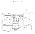
- Fig. 3 is a block diagram showing a constitution of control apparatus.
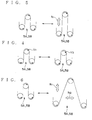
- Fig. 4 is a representation illustrating a speed control of low and high speed rolls.
- Fig. 5 is a representation illustrating a distance adjustment in directions, upward or downward, of low and high speed rolls.
- Fig. 6 is a representation illustrating distance adjustment in directions, upward or downward, and leftward or rightward, of low and high speed rolls.
- Fig. 7 is a representation illustrating air jet to low and high speed rolls.
- Fig. 8 is a representation illustrating air suction at low and high speed rolls.
- Fig. 9 is a representation illustrating adjustment in drawing in a lateral drawing machine.
- Fig. 10 is a plan view showing a lateral drawing machine.
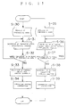
- Fig. 11 is a flow chart showing a control operation for a longitudinal drawing machine.
- Fig. 12 is a flow chart showing a control operation for a lateral drawing machine.
- Fig. 13 is a view showing a constitution of a conventional drawing machine.
- a predetermined control is conducted in a drawing system through comparison of a thickness
- a program stored in a memory of the PC 11 is activated and a target value after longitudinal drawing is read to a register as a comparative data (step 30).
- the thickness gauge 8A disposed at a downstream position of the longitudinal drawing machine 5 measures a film thickness after longitudinal drawing on each block of the film and outputs the measured value.
- the measured thickness is input to the PC 11 (step 31) and comparison processing is conducted between the comparative data and a thickness (step 32).
- the thickness gauge 8 measures a thickness at a predetermined interval based on a timing pulse generated by a CCD timing pulse generating section to input the measured thickness to the PC 11 as occasion demands.
- a comparison processing is conducted and as a result, if a thickness is larger or smaller than a comparative data, a control object and a control quantity to be output to the drawing system are selected (step 33).
- a predetermined control command is output to the drawing system based on the selection result (step 34).
- Target values after longitudinal and lateral drawings are read to a register as comparative data (step 35).
- the thickness gauge 8B disposed at a downstream position of the lateral drawing machine 6 measures thickness of a film after the longitudinal and lateral drawings on each block and outputs the measured values.
- the thickness measured is input to the PC 11 (step 36) and comparison processing is conducted between the comparative data and the thickness (step 37).
- a comparison processing is conducted and as a result, if a thickness is larger or smaller than a comparative data, a control object and a control quantity to be output to the drawing system are selected (step 38).
- a predetermined control command is output to the drawing system based on the selection result (step 39).
- a predetermined control is conducted in a drawing system through comparison of an degree of orientation.
- a control operation is started, a target value after longitudinal drawing stored in a memory of the PC 11 is read in a register as a comparative data (step 40).
- a birefringence is computed in the retardation computing apparatus 10 for computing a retardation from a film thickness of each block from the thickness gauge 8A disposed at a downstream position of the longitudinal drawing machine 5 and optical information of transmitted light through each block of the film read from the spectrometer 9A and the birefringence retardation is input (step 41).
- An degree of orientation of each film block is computed from these parameters (step 42). Thereafter, comparative processing between the comparative data and the degree of orientation is conducted (step 43).
- step 42 if the degree of orientation falls in the range of a comparative data, a current state is maintained and an degree of orientation is again computed from new parameters (step 42) and comparison processing is conducted (step 43).
- measurement of parameters is conducted at a predetermined interval based on a timing pulse generated by the timing pulse generating section 10A and an degree of orientation is computed based on the parameters as occasion demands.
- a control object and a control quantity to be output to the drawing system are selected (step 44).
- a predetermined control demand is output to the drawing system based on the selection result (step 45).
- target values after longitudinal and lateral drawings are read in a register as a comparative data (step 46).
- a birefringence retardation is computed in the retardation computing apparatus 10 for computing a retardation from a film thickness of each block from the thickness gauge 8A disposed at a downstream position of the lateral drawing machine 6 and optical information of transmitted light through each block of the film read from the spectrometer 9A and the birefringence retardation is input (step 47).
- step 48 an degree of orientation of each block film is computed from these parameters. Thereafter, comparison processing is conducted between the comparative data and the degree of orientation (step 49).
- a control object and a control quantity to be output to the drawing system are selected (step 50).
- a predetermined control command is output to the drawing system based on the selection result (step 51).
- a thickness and degree of orientation of a film after longitudinal drawing are independently measured on each blocks divided of the film in a continuous manner and a thickness and degree of orientation of a film after longitudinal and lateral drawings are independently measured on each blocks divided of the film in a continuous manner, and a predetermined control operation is conducted in the drawing system, whereby a thickness and degree of orientation of an oriented film are controlled in a uniform manner. Breakdown or the like of a film is, as describe above, prevented from occurring by controlling a thickness and degree of orientation in a uniform manner in a high speed molding.
- a birefringence measuring method of the present invention three parameters required for computation of a birefringence retardation, that is three parameter of a first extremum wavelength ⁇ 1 and a second extremum wavelength ⁇ 2 assuming extrema in the transmitted light spectrum, and the number M (including extrema of the first and second extremum wavelengths ⁇ 1, ⁇ 2) of extrema between the first and second extremum wavelengths can be detected and output in real time and the three parameters are detected by an exclusive use of retardation computing circuit and thereby a load on a computer can be reduced and as a result, measurement of a birefringence in real time can be realized.
Landscapes
- Engineering & Computer Science (AREA)
- Mechanical Engineering (AREA)
- General Health & Medical Sciences (AREA)
- Chemical & Material Sciences (AREA)
- Analytical Chemistry (AREA)
- Biochemistry (AREA)
- Physics & Mathematics (AREA)
- General Physics & Mathematics (AREA)
- Immunology (AREA)
- Pathology (AREA)
- Life Sciences & Earth Sciences (AREA)
- Health & Medical Sciences (AREA)
- Shaping By String And By Release Of Stress In Plastics And The Like (AREA)
- Length Measuring Devices By Optical Means (AREA)
Applications Claiming Priority (6)
| Application Number | Priority Date | Filing Date | Title |
|---|---|---|---|
| JP113958/97 | 1997-05-01 | ||
| JP11395897 | 1997-05-01 | ||
| JP11395897 | 1997-05-01 | ||
| JP32474297 | 1997-11-26 | ||
| JP32474297A JP3858101B2 (ja) | 1997-05-01 | 1997-11-26 | 延伸フィルム製造設備、及び製造方法 |
| JP324742/97 | 1997-11-26 |
Publications (2)
| Publication Number | Publication Date |
|---|---|
| EP0875359A2 true EP0875359A2 (de) | 1998-11-04 |
| EP0875359A3 EP0875359A3 (de) | 1999-11-24 |
Family
ID=26452819
Family Applications (1)
| Application Number | Title | Priority Date | Filing Date |
|---|---|---|---|
| EP98107950A Withdrawn EP0875359A3 (de) | 1997-05-01 | 1998-04-30 | Anlage zur Herstellung einer orientierten Folie und Verfahren zum Messen der Doppelbrechung |
Country Status (5)
| Country | Link |
|---|---|
| US (1) | US6190153B1 (de) |
| EP (1) | EP0875359A3 (de) |
| JP (1) | JP3858101B2 (de) |
| CN (1) | CN1198377A (de) |
| TW (1) | TW436420B (de) |
Cited By (2)
| Publication number | Priority date | Publication date | Assignee | Title |
|---|---|---|---|---|
| WO2006063641A1 (de) | 2004-12-16 | 2006-06-22 | Brückner Maschinenbau GmbH | Vorrichtung und verfahren zum antrieb einer vorheizwalzenanordnung in einer kalander-vorrichtung |
| WO2016192698A1 (de) * | 2015-06-03 | 2016-12-08 | Reifenhäuser GmbH & Co. KG Maschinenfabrik | Anlage zum herstellen einer folienbahn und verfahren zum betreiben einer solchen anlage |
Families Citing this family (42)
| Publication number | Priority date | Publication date | Assignee | Title |
|---|---|---|---|---|
| JP4856830B2 (ja) * | 2001-09-28 | 2012-01-18 | 株式会社クラレ | 延伸された積層体の製造方法とその装置 |
| DE10300375B4 (de) * | 2003-01-06 | 2013-06-13 | Windmöller & Hölscher Kg | Verfahren zur Regelung der Dicke extrudierter Folie I |
| US7738993B2 (en) * | 2003-10-10 | 2010-06-15 | Boston Scientific Scimed, Inc. | Extrusion of articles |
| JP2005257508A (ja) * | 2004-03-12 | 2005-09-22 | Nokodai Tlo Kk | 複屈折特性測定装置および複屈折特性測定方法 |
| US7749411B2 (en) * | 2004-12-01 | 2010-07-06 | Konica Minolta Opto, Inc. | Optical film and production method of the same |
| US7298492B2 (en) * | 2004-12-29 | 2007-11-20 | Honeywell International Inc. | Method and system for on-line measurement of thickness and birefringence of thin plastic films |
| JP4652853B2 (ja) * | 2005-03-09 | 2011-03-16 | 三井化学東セロ株式会社 | 容器及びその製造方法 |
| TW200702156A (en) | 2005-03-28 | 2007-01-16 | Konica Minolta Opto Inc | Optical film, method for producing the same and polarizing plate using the same |
| KR101236591B1 (ko) * | 2005-06-01 | 2013-02-22 | 쓰리엠 이노베이티브 프로퍼티즈 컴파니 | 채널 차단기를 이용한 웨브 횡단 열분배 시스템 및 방법 |
| EP1899141A1 (de) * | 2005-06-01 | 2008-03-19 | 3M Innovative Properties Company | Querbahnwärmeverteilsystem und neupositionierbare heizvorrichtungen verwendendes verfahren |
| EP1890861B1 (de) * | 2005-06-01 | 2016-03-30 | 3M Innovative Properties Company | Verfahren zur steuerung des querbahnstärkenprofils biaxial orientierter polymerfolien |
| US8206633B2 (en) | 2005-07-26 | 2012-06-26 | Hunter Douglas Inc. | Method and apparatus for forming slats for fabric in coverings for architectural openings |
| WO2007046228A1 (ja) * | 2005-10-19 | 2007-04-26 | Konica Minolta Opto, Inc. | 光学フィルムの製造方法、光学フィルムの製造装置、及び光学フィルム |
| US7829855B2 (en) * | 2006-01-17 | 2010-11-09 | University Of Northern British Columbia | Methods and apparatus for determining fibre orientation |
| JP2007285871A (ja) * | 2006-04-17 | 2007-11-01 | Fujifilm Corp | 複屈折測定装置 |
| JP5019110B2 (ja) * | 2007-06-07 | 2012-09-05 | 横河電機株式会社 | 赤外線厚さ計 |
| JP5366426B2 (ja) * | 2008-04-04 | 2013-12-11 | 東芝機械株式会社 | 多孔性フィルムの製膜方法及び多孔性フィルム製膜用の逐次二軸延伸装置 |
| JP2008290780A (ja) * | 2008-08-12 | 2008-12-04 | Tohcello Co Ltd | ガスバリア性膜及びその積層体 |
| JP4966996B2 (ja) * | 2009-05-19 | 2012-07-04 | 東芝機械株式会社 | レール支持装置およびシートの延伸方法 |
| DE102009033171B4 (de) * | 2009-07-13 | 2016-03-03 | Hosokawa Alpine Ag | Verfahren zur Regelung der Foliendicke von verstreckten Schlauchfolien sowie Vorrichtung zur Durchführung des Verfahrens |
| CN102725114B (zh) * | 2010-01-26 | 2014-10-08 | 宇部兴产株式会社 | 聚酰亚胺膜的制造方法及制造装置 |
| CN102401633B (zh) * | 2010-09-10 | 2014-04-16 | 国家纳米科学中心 | 多孔氧化铝薄膜的阻挡层厚度的检测方法 |
| JP5653747B2 (ja) * | 2010-12-24 | 2015-01-14 | 富士フイルム株式会社 | 光学フィルムの製造方法 |
| JP5660026B2 (ja) * | 2011-12-28 | 2015-01-28 | 信越半導体株式会社 | 膜厚分布測定方法 |
| KR20150013865A (ko) * | 2012-05-22 | 2015-02-05 | 닛토덴코 가부시키가이샤 | 비수전해질 축전 디바이스용 세퍼레이터의 제조 방법 및 에폭시 수지 다공질막의 제조 방법 |
| CN103674848B (zh) * | 2013-12-09 | 2016-04-20 | 东南大学 | 一种薄膜取向特性检测装置及其应用 |
| CN104441750B (zh) * | 2014-12-05 | 2016-06-29 | 苏州均华精密机械有限公司 | 具测厚能力的压合机及其方法 |
| JP6681244B2 (ja) * | 2016-03-30 | 2020-04-15 | キヤノン株式会社 | 画像処理装置、その制御方法、及びプログラム |
| US20180036936A1 (en) * | 2016-08-04 | 2018-02-08 | General Electric Company | Apparatus and method of processing a continuous sheet of polymer material |
| EP3995284B1 (de) * | 2017-02-08 | 2024-11-13 | Cryovac, LLC | Verfahren und systeme zur inline-inspektion einer funktionalen folienschicht mit detektierbarer komponente |
| US11426914B2 (en) * | 2019-03-15 | 2022-08-30 | The Japan Steel Works, Ltd. | Resin film manufacturing device and resin film manufacturing method |
| US11718011B2 (en) * | 2019-05-10 | 2023-08-08 | The Royal Institution For The Advancement Of Learning/Mcgill University | Method and system for regulating an extrusion process |
| CN112140440A (zh) * | 2019-06-27 | 2020-12-29 | 安徽省众望科希盟科技有限公司 | 一种压延膜厚度自动控制方法 |
| CN111208136B (zh) * | 2020-01-16 | 2023-04-07 | 东莞维科电池有限公司 | 一种在线检查涂层隔膜朝向的方法及装置 |
| CN113686682B (zh) * | 2021-09-14 | 2024-05-28 | 宁波勤邦新材料科技股份有限公司 | 一种太阳能背板基膜的在线检测装置及其工作方法 |
| KR102581872B1 (ko) * | 2021-10-01 | 2023-09-25 | 금호타이어 주식회사 | 에이펙스 압출 라인 속도 자동 피드백 제어 장치 |
| JP7096943B1 (ja) * | 2021-10-29 | 2022-07-06 | 日東電工株式会社 | 延伸フィルムの製造方法および光学積層体の製造方法 |
| JP7645770B2 (ja) * | 2021-11-01 | 2025-03-14 | カナデビア株式会社 | 成形条件調整装置および成形条件調整方法 |
| KR102667886B1 (ko) * | 2022-01-07 | 2024-05-22 | 주식회사 케이엔제이 | 롤투롤 실시간 검사 시스템 |
| CN116638722B (zh) * | 2023-05-29 | 2026-02-06 | 浙江恒熙高新材料科技有限公司 | 高阻隔mdope膜的制备设备及方法 |
| CN117484817B (zh) * | 2023-12-06 | 2024-10-18 | 江苏新义薄膜有限公司 | 超薄防静电聚丙烯薄膜的制备方法及装置 |
| CN121552643B (zh) * | 2026-01-21 | 2026-04-28 | 泉州嘉德利电子材料股份公司 | 抗拉伸聚丙烯薄膜的生产方法 |
Family Cites Families (19)
| Publication number | Priority date | Publication date | Assignee | Title |
|---|---|---|---|---|
| GB1448669A (en) * | 1972-09-08 | 1976-09-08 | Bakelite Xylonite Ltd | Profile determining and/or controlling system |
| JPS5247070A (en) * | 1975-10-13 | 1977-04-14 | Mitsubishi Plastics Ind | Method for elongation of linear polyester films |
| GB1594710A (en) | 1977-12-21 | 1981-08-05 | Lippke Gmbh Co Kg Paul | Manufacture of films of plastics material |
| JPS56133135A (en) * | 1980-03-21 | 1981-10-19 | Mitsubishi Heavy Ind Ltd | Controlling method for thickness of film |
| US4432917A (en) * | 1981-11-18 | 1984-02-21 | Mobil Oil Corporation | Method for improving thickness uniformity of stretch oriented polyacrylonitrile film |
| JPS59224547A (ja) * | 1983-06-03 | 1984-12-17 | Kanzaki Paper Mfg Co Ltd | 繊維シ−トの繊維配向測定方法 |
| DE3543632A1 (de) * | 1985-12-11 | 1987-06-19 | Hoechst Ag | Verfahren und vorrichtung zur bestimmung von dicken- und/oder orientierungsaenderungen innerhalb einer optisch aktiven materialbahn |
| JPS63315221A (ja) * | 1987-06-19 | 1988-12-22 | Diafoil Co Ltd | 熱可塑性フイルムの延伸制御方法 |
| DE3875433T2 (de) * | 1987-07-17 | 1993-04-22 | Toray Industries | Methode der schichtdickenregelung eines bandfoermigen materials. |
| JP2612244B2 (ja) * | 1988-12-29 | 1997-05-21 | 王子油化合成紙株式会社 | 延伸樹脂フィルムの肉厚制御方法 |
| JPH0465222A (ja) * | 1990-07-05 | 1992-03-02 | Mitsubishi Heavy Ind Ltd | フィルム・シートの配向度インライン計測装置 |
| JPH0534911Y2 (de) * | 1990-09-27 | 1993-09-03 | ||
| JPH04283650A (ja) * | 1991-03-12 | 1992-10-08 | Kanzaki Paper Mfg Co Ltd | 複屈折測定装置 |
| DE9212406U1 (de) | 1992-09-15 | 1992-12-17 | Röhm GmbH, 6100 Darmstadt | Vorrichtung zur Ermittlung und Einstellung der Wulsthöhe im Glättwerkspalt bei der Extrusion von Kunststoff-Folien |
| JP3342517B2 (ja) * | 1992-10-27 | 2002-11-11 | 株式会社クラレ | Pva系フィルム及び光学用フィルムの製造方法 |
| KR0171637B1 (ko) * | 1993-09-13 | 1999-03-20 | 사또오 후미오 | 배향막 평가 장치 |
| JP3379287B2 (ja) * | 1995-06-26 | 2003-02-24 | 松下電器産業株式会社 | 複屈折層ギャップ厚測定方法 |
| JPH09218307A (ja) * | 1996-02-13 | 1997-08-19 | Sekisui Chem Co Ltd | 位相差フィルムの製造方法 |
| US5779962A (en) * | 1996-04-01 | 1998-07-14 | Minnesota Mining And Manufacturing Company | Extruding thin multiphase polymer films |
-
1997
- 1997-11-26 JP JP32474297A patent/JP3858101B2/ja not_active Expired - Fee Related
-
1998
- 1998-04-30 EP EP98107950A patent/EP0875359A3/de not_active Withdrawn
- 1998-04-30 US US09/069,732 patent/US6190153B1/en not_active Expired - Fee Related
- 1998-04-30 TW TW087106691A patent/TW436420B/zh not_active IP Right Cessation
- 1998-05-01 CN CN98109459A patent/CN1198377A/zh active Pending
Cited By (4)
| Publication number | Priority date | Publication date | Assignee | Title |
|---|---|---|---|---|
| WO2006063641A1 (de) | 2004-12-16 | 2006-06-22 | Brückner Maschinenbau GmbH | Vorrichtung und verfahren zum antrieb einer vorheizwalzenanordnung in einer kalander-vorrichtung |
| JP2008524011A (ja) * | 2004-12-16 | 2008-07-10 | ブリュックナー マシーネンバウ ゲーエムベーハー | カレンダ装置の予熱ローラ装置を駆動する装置及び方法 |
| US7752961B2 (en) | 2004-12-16 | 2010-07-13 | Bruckner Maschinenbau Gmbh | Device and method for driving a preheating roll assembly in a calender unit |
| WO2016192698A1 (de) * | 2015-06-03 | 2016-12-08 | Reifenhäuser GmbH & Co. KG Maschinenfabrik | Anlage zum herstellen einer folienbahn und verfahren zum betreiben einer solchen anlage |
Also Published As
| Publication number | Publication date |
|---|---|
| CN1198377A (zh) | 1998-11-11 |
| JP3858101B2 (ja) | 2006-12-13 |
| EP0875359A3 (de) | 1999-11-24 |
| JPH1110728A (ja) | 1999-01-19 |
| TW436420B (en) | 2001-05-28 |
| US6190153B1 (en) | 2001-02-20 |
Similar Documents
| Publication | Publication Date | Title |
|---|---|---|
| US6190153B1 (en) | Oriented film producing facility with thickness and orientation control means | |
| US5158724A (en) | Bank quantity monitoring method and apparatus, sheet forming method and apparatus, and sheet temperature measuring method and apparatus | |
| CA1333001C (en) | Method of and apparatus for manufacturing biaxially oriented film | |
| JP4525326B2 (ja) | フィルム延伸装置およびフィルム延伸方法 | |
| US5262101A (en) | Bank quantity monitoring method and apparatus, sheet forming method and apparatus, and sheet temperature measuring method and apparatus | |
| TWI859388B (zh) | 相位差薄膜之製造方法 | |
| JPH08501506A (ja) | カレンダにおける膨隆大きさの調整のための方法とその装置 | |
| JP5136490B2 (ja) | 光学フィルムの製造装置 | |
| JP4115536B2 (ja) | フィルム加熱方法及び加熱装置並びにフィルム温度測定装置 | |
| US6863517B2 (en) | Apparatus and method for measuring and of controlling the gap between polymer sheet cooling rolls | |
| US6406285B1 (en) | Apparatus for measuring and of controlling the gap between polymer sheet cooling rolls | |
| EP0160488A2 (de) | Verfahren zur Messung der Orientierung von Bestandteilen in Folien | |
| KR102531094B1 (ko) | 연신 필름의 제조 방법 및 광학 적층체의 제조 방법 | |
| JP2023046840A (ja) | 延伸フィルムの製造方法および光学積層体の製造方法 | |
| CA2043655C (en) | Reduction of sag in a flattened web of tubular film | |
| KR102461852B1 (ko) | 연신 필름의 제조 방법 및 광학 적층체의 제조 방법 | |
| KR102555876B1 (ko) | 연신 필름의 제조 방법 및 광학 적층체의 제조 방법 | |
| KR102530417B1 (ko) | 연신 필름의 제조 방법, 광학 적층체의 제조 방법 및 필름 연신 장치 | |
| KR19980086693A (ko) | 연신 필름 제조 설비 및 복굴절 측정 방법 | |
| JPH0534911Y2 (de) | ||
| US20250135703A1 (en) | Resin film manufacturing apparatus and its control method | |
| JPH0812144A (ja) | ウエブの製造方法および製造装置 | |
| CN115122621A (zh) | 延伸膜的制造方法 | |
| JP5561345B2 (ja) | 光学フィルムの製造方法 | |
| JPH10311803A (ja) | 異方性分布の測定方法とその装置 |
Legal Events
| Date | Code | Title | Description |
|---|---|---|---|
| PUAI | Public reference made under article 153(3) epc to a published international application that has entered the european phase |
Free format text: ORIGINAL CODE: 0009012 |
|
| AK | Designated contracting states |
Kind code of ref document: A2 Designated state(s): DE FR GB IT NL |
|
| AX | Request for extension of the european patent |
Free format text: AL;LT;LV;MK;RO;SI |
|
| PUAL | Search report despatched |
Free format text: ORIGINAL CODE: 0009013 |
|
| AK | Designated contracting states |
Kind code of ref document: A3 Designated state(s): AT BE CH CY DE DK ES FI FR GB GR IE IT LI LU MC NL PT SE |
|
| AX | Request for extension of the european patent |
Free format text: AL;LT;LV;MK;RO;SI |
|
| 17P | Request for examination filed |
Effective date: 20000330 |
|
| AKX | Designation fees paid |
Free format text: DE FR GB IT NL |
|
| 17Q | First examination report despatched |
Effective date: 20010313 |
|
| STAA | Information on the status of an ep patent application or granted ep patent |
Free format text: STATUS: THE APPLICATION IS DEEMED TO BE WITHDRAWN |
|
| 18D | Application deemed to be withdrawn |
Effective date: 20011218 |