EP0875362A2 - Mittels HF-Schweissen hergestellte Verbindung zwischen Rohr und Anbindungselement - Google Patents
Mittels HF-Schweissen hergestellte Verbindung zwischen Rohr und Anbindungselement Download PDFInfo
- Publication number
- EP0875362A2 EP0875362A2 EP98104079A EP98104079A EP0875362A2 EP 0875362 A2 EP0875362 A2 EP 0875362A2 EP 98104079 A EP98104079 A EP 98104079A EP 98104079 A EP98104079 A EP 98104079A EP 0875362 A2 EP0875362 A2 EP 0875362A2
- Authority
- EP
- European Patent Office
- Prior art keywords
- connection
- connecting element
- tube
- pipe
- electrode
- Prior art date
- Legal status (The legal status is an assumption and is not a legal conclusion. Google has not performed a legal analysis and makes no representation as to the accuracy of the status listed.)
- Withdrawn
Links
Images
Classifications
-
- B—PERFORMING OPERATIONS; TRANSPORTING
- B29—WORKING OF PLASTICS; WORKING OF SUBSTANCES IN A PLASTIC STATE IN GENERAL
- B29C—SHAPING OR JOINING OF PLASTICS; SHAPING OF MATERIAL IN A PLASTIC STATE, NOT OTHERWISE PROVIDED FOR; AFTER-TREATMENT OF THE SHAPED PRODUCTS, e.g. REPAIRING
- B29C65/00—Joining or sealing of preformed parts, e.g. welding of plastics materials; Apparatus therefor
- B29C65/02—Joining or sealing of preformed parts, e.g. welding of plastics materials; Apparatus therefor by heating, with or without pressure
- B29C65/04—Dielectric heating, e.g. high-frequency welding, i.e. radio frequency welding of plastic materials having dielectric properties, e.g. PVC
-
- F—MECHANICAL ENGINEERING; LIGHTING; HEATING; WEAPONS; BLASTING
- F16—ENGINEERING ELEMENTS AND UNITS; GENERAL MEASURES FOR PRODUCING AND MAINTAINING EFFECTIVE FUNCTIONING OF MACHINES OR INSTALLATIONS; THERMAL INSULATION IN GENERAL
- F16L—PIPES; JOINTS OR FITTINGS FOR PIPES; SUPPORTS FOR PIPES, CABLES OR PROTECTIVE TUBING; MEANS FOR THERMAL INSULATION IN GENERAL
- F16L13/00—Non-disconnectable pipe joints, e.g. soldered, adhesive, or caulked joints
- F16L13/02—Welded joints
-
- B—PERFORMING OPERATIONS; TRANSPORTING
- B29—WORKING OF PLASTICS; WORKING OF SUBSTANCES IN A PLASTIC STATE IN GENERAL
- B29C—SHAPING OR JOINING OF PLASTICS; SHAPING OF MATERIAL IN A PLASTIC STATE, NOT OTHERWISE PROVIDED FOR; AFTER-TREATMENT OF THE SHAPED PRODUCTS, e.g. REPAIRING
- B29C66/00—General aspects of processes or apparatus for joining preformed parts
- B29C66/01—General aspects dealing with the joint area or with the area to be joined
- B29C66/05—Particular design of joint configurations
- B29C66/10—Particular design of joint configurations particular design of the joint cross-sections
- B29C66/11—Joint cross-sections comprising a single joint-segment, i.e. one of the parts to be joined comprising a single joint-segment in the joint cross-section
- B29C66/112—Single lapped joints
- B29C66/1122—Single lap to lap joints, i.e. overlap joints
-
- B—PERFORMING OPERATIONS; TRANSPORTING
- B29—WORKING OF PLASTICS; WORKING OF SUBSTANCES IN A PLASTIC STATE IN GENERAL
- B29C—SHAPING OR JOINING OF PLASTICS; SHAPING OF MATERIAL IN A PLASTIC STATE, NOT OTHERWISE PROVIDED FOR; AFTER-TREATMENT OF THE SHAPED PRODUCTS, e.g. REPAIRING
- B29C66/00—General aspects of processes or apparatus for joining preformed parts
- B29C66/50—General aspects of joining tubular articles; General aspects of joining long products, i.e. bars or profiled elements; General aspects of joining single elements to tubular articles, hollow articles or bars; General aspects of joining several hollow-preforms to form hollow or tubular articles
- B29C66/51—Joining tubular articles, profiled elements or bars; Joining single elements to tubular articles, hollow articles or bars; Joining several hollow-preforms to form hollow or tubular articles
- B29C66/52—Joining tubular articles, bars or profiled elements
- B29C66/522—Joining tubular articles
-
- B—PERFORMING OPERATIONS; TRANSPORTING
- B29—WORKING OF PLASTICS; WORKING OF SUBSTANCES IN A PLASTIC STATE IN GENERAL
- B29C—SHAPING OR JOINING OF PLASTICS; SHAPING OF MATERIAL IN A PLASTIC STATE, NOT OTHERWISE PROVIDED FOR; AFTER-TREATMENT OF THE SHAPED PRODUCTS, e.g. REPAIRING
- B29C66/00—General aspects of processes or apparatus for joining preformed parts
- B29C66/50—General aspects of joining tubular articles; General aspects of joining long products, i.e. bars or profiled elements; General aspects of joining single elements to tubular articles, hollow articles or bars; General aspects of joining several hollow-preforms to form hollow or tubular articles
- B29C66/51—Joining tubular articles, profiled elements or bars; Joining single elements to tubular articles, hollow articles or bars; Joining several hollow-preforms to form hollow or tubular articles
- B29C66/53—Joining single elements to tubular articles, hollow articles or bars
- B29C66/534—Joining single elements to open ends of tubular or hollow articles or to the ends of bars
- B29C66/5344—Joining single elements to open ends of tubular or hollow articles or to the ends of bars said single elements being substantially annular, i.e. of finite length, e.g. joining flanges to tube ends
-
- B—PERFORMING OPERATIONS; TRANSPORTING
- B29—WORKING OF PLASTICS; WORKING OF SUBSTANCES IN A PLASTIC STATE IN GENERAL
- B29C—SHAPING OR JOINING OF PLASTICS; SHAPING OF MATERIAL IN A PLASTIC STATE, NOT OTHERWISE PROVIDED FOR; AFTER-TREATMENT OF THE SHAPED PRODUCTS, e.g. REPAIRING
- B29C66/00—General aspects of processes or apparatus for joining preformed parts
- B29C66/50—General aspects of joining tubular articles; General aspects of joining long products, i.e. bars or profiled elements; General aspects of joining single elements to tubular articles, hollow articles or bars; General aspects of joining several hollow-preforms to form hollow or tubular articles
- B29C66/61—Joining from or joining on the inside
- B29C66/612—Making circumferential joints
-
- B—PERFORMING OPERATIONS; TRANSPORTING
- B29—WORKING OF PLASTICS; WORKING OF SUBSTANCES IN A PLASTIC STATE IN GENERAL
- B29C—SHAPING OR JOINING OF PLASTICS; SHAPING OF MATERIAL IN A PLASTIC STATE, NOT OTHERWISE PROVIDED FOR; AFTER-TREATMENT OF THE SHAPED PRODUCTS, e.g. REPAIRING
- B29C66/00—General aspects of processes or apparatus for joining preformed parts
- B29C66/50—General aspects of joining tubular articles; General aspects of joining long products, i.e. bars or profiled elements; General aspects of joining single elements to tubular articles, hollow articles or bars; General aspects of joining several hollow-preforms to form hollow or tubular articles
- B29C66/63—Internally supporting the article during joining
-
- B—PERFORMING OPERATIONS; TRANSPORTING
- B29—WORKING OF PLASTICS; WORKING OF SUBSTANCES IN A PLASTIC STATE IN GENERAL
- B29C—SHAPING OR JOINING OF PLASTICS; SHAPING OF MATERIAL IN A PLASTIC STATE, NOT OTHERWISE PROVIDED FOR; AFTER-TREATMENT OF THE SHAPED PRODUCTS, e.g. REPAIRING
- B29C66/00—General aspects of processes or apparatus for joining preformed parts
- B29C66/70—General aspects of processes or apparatus for joining preformed parts characterised by the composition, physical properties or the structure of the material of the parts to be joined; Joining with non-plastics material
- B29C66/73—General aspects of processes or apparatus for joining preformed parts characterised by the composition, physical properties or the structure of the material of the parts to be joined; Joining with non-plastics material characterised by the intensive physical properties of the material of the parts to be joined, by the optical properties of the material of the parts to be joined, by the extensive physical properties of the parts to be joined, by the state of the material of the parts to be joined or by the material of the parts to be joined being a thermoplastic or a thermoset
- B29C66/739—General aspects of processes or apparatus for joining preformed parts characterised by the composition, physical properties or the structure of the material of the parts to be joined; Joining with non-plastics material characterised by the intensive physical properties of the material of the parts to be joined, by the optical properties of the material of the parts to be joined, by the extensive physical properties of the parts to be joined, by the state of the material of the parts to be joined or by the material of the parts to be joined being a thermoplastic or a thermoset characterised by the material of the parts to be joined being a thermoplastic or a thermoset
- B29C66/7392—General aspects of processes or apparatus for joining preformed parts characterised by the composition, physical properties or the structure of the material of the parts to be joined; Joining with non-plastics material characterised by the intensive physical properties of the material of the parts to be joined, by the optical properties of the material of the parts to be joined, by the extensive physical properties of the parts to be joined, by the state of the material of the parts to be joined or by the material of the parts to be joined being a thermoplastic or a thermoset characterised by the material of the parts to be joined being a thermoplastic or a thermoset characterised by the material of at least one of the parts being a thermoplastic
- B29C66/73921—General aspects of processes or apparatus for joining preformed parts characterised by the composition, physical properties or the structure of the material of the parts to be joined; Joining with non-plastics material characterised by the intensive physical properties of the material of the parts to be joined, by the optical properties of the material of the parts to be joined, by the extensive physical properties of the parts to be joined, by the state of the material of the parts to be joined or by the material of the parts to be joined being a thermoplastic or a thermoset characterised by the material of the parts to be joined being a thermoplastic or a thermoset characterised by the material of at least one of the parts being a thermoplastic characterised by the materials of both parts being thermoplastics
-
- B—PERFORMING OPERATIONS; TRANSPORTING
- B29—WORKING OF PLASTICS; WORKING OF SUBSTANCES IN A PLASTIC STATE IN GENERAL
- B29C—SHAPING OR JOINING OF PLASTICS; SHAPING OF MATERIAL IN A PLASTIC STATE, NOT OTHERWISE PROVIDED FOR; AFTER-TREATMENT OF THE SHAPED PRODUCTS, e.g. REPAIRING
- B29C66/00—General aspects of processes or apparatus for joining preformed parts
- B29C66/80—General aspects of machine operations or constructions and parts thereof
- B29C66/83—General aspects of machine operations or constructions and parts thereof characterised by the movement of the joining or pressing tools
- B29C66/832—Reciprocating joining or pressing tools
- B29C66/8322—Joining or pressing tools reciprocating along one axis
- B29C66/83221—Joining or pressing tools reciprocating along one axis cooperating reciprocating tools, each tool reciprocating along one axis
-
- F—MECHANICAL ENGINEERING; LIGHTING; HEATING; WEAPONS; BLASTING
- F16—ENGINEERING ELEMENTS AND UNITS; GENERAL MEASURES FOR PRODUCING AND MAINTAINING EFFECTIVE FUNCTIONING OF MACHINES OR INSTALLATIONS; THERMAL INSULATION IN GENERAL
- F16L—PIPES; JOINTS OR FITTINGS FOR PIPES; SUPPORTS FOR PIPES, CABLES OR PROTECTIVE TUBING; MEANS FOR THERMAL INSULATION IN GENERAL
- F16L47/00—Connecting arrangements or other fittings specially adapted to be made of plastics or to be used with pipes made of plastics
- F16L47/06—Connecting arrangements or other fittings specially adapted to be made of plastics or to be used with pipes made of plastics with sleeve or socket formed by or in the pipe end
-
- F—MECHANICAL ENGINEERING; LIGHTING; HEATING; WEAPONS; BLASTING
- F16—ENGINEERING ELEMENTS AND UNITS; GENERAL MEASURES FOR PRODUCING AND MAINTAINING EFFECTIVE FUNCTIONING OF MACHINES OR INSTALLATIONS; THERMAL INSULATION IN GENERAL
- F16L—PIPES; JOINTS OR FITTINGS FOR PIPES; SUPPORTS FOR PIPES, CABLES OR PROTECTIVE TUBING; MEANS FOR THERMAL INSULATION IN GENERAL
- F16L9/00—Rigid pipes
- F16L9/12—Rigid pipes of plastics with or without reinforcement
- F16L9/125—Rigid pipes of plastics with or without reinforcement electrically conducting
-
- B—PERFORMING OPERATIONS; TRANSPORTING
- B29—WORKING OF PLASTICS; WORKING OF SUBSTANCES IN A PLASTIC STATE IN GENERAL
- B29C—SHAPING OR JOINING OF PLASTICS; SHAPING OF MATERIAL IN A PLASTIC STATE, NOT OTHERWISE PROVIDED FOR; AFTER-TREATMENT OF THE SHAPED PRODUCTS, e.g. REPAIRING
- B29C66/00—General aspects of processes or apparatus for joining preformed parts
- B29C66/70—General aspects of processes or apparatus for joining preformed parts characterised by the composition, physical properties or the structure of the material of the parts to be joined; Joining with non-plastics material
- B29C66/71—General aspects of processes or apparatus for joining preformed parts characterised by the composition, physical properties or the structure of the material of the parts to be joined; Joining with non-plastics material characterised by the composition of the plastics material of the parts to be joined
-
- B—PERFORMING OPERATIONS; TRANSPORTING
- B29—WORKING OF PLASTICS; WORKING OF SUBSTANCES IN A PLASTIC STATE IN GENERAL
- B29C—SHAPING OR JOINING OF PLASTICS; SHAPING OF MATERIAL IN A PLASTIC STATE, NOT OTHERWISE PROVIDED FOR; AFTER-TREATMENT OF THE SHAPED PRODUCTS, e.g. REPAIRING
- B29C66/00—General aspects of processes or apparatus for joining preformed parts
- B29C66/70—General aspects of processes or apparatus for joining preformed parts characterised by the composition, physical properties or the structure of the material of the parts to be joined; Joining with non-plastics material
- B29C66/72—General aspects of processes or apparatus for joining preformed parts characterised by the composition, physical properties or the structure of the material of the parts to be joined; Joining with non-plastics material characterised by the structure of the material of the parts to be joined
- B29C66/723—General aspects of processes or apparatus for joining preformed parts characterised by the composition, physical properties or the structure of the material of the parts to be joined; Joining with non-plastics material characterised by the structure of the material of the parts to be joined being multi-layered
-
- B—PERFORMING OPERATIONS; TRANSPORTING
- B29—WORKING OF PLASTICS; WORKING OF SUBSTANCES IN A PLASTIC STATE IN GENERAL
- B29K—INDEXING SCHEME ASSOCIATED WITH SUBCLASSES B29B, B29C OR B29D, RELATING TO MOULDING MATERIALS OR TO MATERIALS FOR MOULDS, REINFORCEMENTS, FILLERS OR PREFORMED PARTS, e.g. INSERTS
- B29K2071/00—Use of polyethers, e.g. PEEK, i.e. polyether-etherketone or PEK, i.e. polyetherketone or derivatives thereof, as moulding material
Definitions
- the invention relates to a welded connection between a plastic tube and a connecting element, which by means of an electrical high-frequency field will be produced.
- connection element to the pipe to be attached acts.
- the geometrical Design of the mandrel has z. B. the shape of a pine cone, the Outside diameter of the mandrel is larger than the inside diameter of the tube.
- the Mandrel of the connection element is inserted into the tube at high speed introduced, the tube expands due to the smaller inner diameter.
- connection technology due to the expansion of the Circumferential stress caused by the pipe can be caused due to Relaxation processes over time, but especially with higher ones Usage temperatures, such as. B. prevail in coolant lines mechanical loads (vibrations) or due to the influence of fuel fuel-carrying pipe systems become smaller.
- higher ones Usage temperatures such as. B. prevail in coolant lines mechanical loads (vibrations) or due to the influence of fuel fuel-carrying pipe systems become smaller.
- connection techniques have been developed to solve this problem
- e.g. B. a suitably designed quick connector into the pipe introduced and then set in rotation. Due to the frictional forces between The quick connector and pipe heat up the plastics in the joint surface and can be welded together if the melting temperature is exceeded.
- This allows leak-free connections between a pipe and a pipe Connection element are made; due to the high friction forces between the pipe and Quick Connector is this connection method with a high Torsional stress connected in particular to the tube, which negatively affects the Properties of the pipe can affect.
- Another disadvantage of Rotational welding is the welding process, that is, by the friction effect Liquefied material in the joint area between Quick Connector and pipe.
- connection between the connecting element and tube both made consist of thermoplastic, by welding using an electrical High frequency field (RF welding) is produced.
- RF welding electrical High frequency field
- the connection point is surrounded by an electrode, for example consists of two electrode jaws, which may be designed at the same time are that they can apply pressure.
- an electrode for example consists of two electrode jaws, which may be designed at the same time are that they can apply pressure.
- As a counterpart to the outside arranged electrode becomes an electrode in one embodiment of the invention pushed inside the connector.
- the tube can consist of one layer or it can be a multi-layer tube available.
- Multi-layer pipes are state of the art; they are from a variety of Patent applications are known and are used in particular in the automotive industry used to a large extent (see, for example, EP-A-0 730 115 and those mentioned therein Writings).
- the choice of material for the connecting element depends on the material of the pipe or in the case of multi-layer pipes according to the material with the connecting element welding layer.
- the materials must be identical or at least be compatible with each other, the welded joint both inside the tube and can also be done on the outside of the pipe, depending on whether the connecting element is inserted or is postponed.
- Molding compounds are used, which are mainly made of polyamide 6 (PA6), PA6.6, PA6.12, PA11, PA12, polyketone, polybutylene terephthalate, polyvinylidene fluoride or Polyvinyl chloride exist.
- a multilayer connection element can be used one or more layers of polyoxymethylene, polyethylene or Polypropylene included. All molding compounds used can, according to the State of the art, fillers, fibrous reinforcing agents and / or electrical contain conductive additives.
- connection element made of a conductive material
- the tube as a whole can be made electrically conductive or contain a conductive layer.
- Such pipes are state of the art (e.g. DE-C-40 01 125 and EP-A-0 730 115). All in all, some or all of them can of the materials used must be electrically conductive.
- the welded connection produced according to the invention is highly axially loadable and permanently leak-free. It is used, for example, in pipe systems to guide gaseous or liquid media, such as in coolant, fuel or Air conditioning duct systems, the duct system depending on the requirements can either contain one or more of these welded joints.
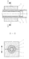
- a tube (2) made of a similar polyamide molding compound is pushed over the mandrel of a connector (1) made of a polyamide molding compound and is surrounded by two jaws (3) .
- the joining pressure required for welding is applied with the help of the two jaws.
- the jaws serve as an electrode.
- the counter electrode (4) is inserted into the connector.
- a high-frequency field is then generated between the two electrodes for about 3 to 4 seconds, with which both the molding compound of the connector and that of the pipe is heated, so that the weld takes place in the interface between the pipe and the connector. After a brief cooling, the weld is mechanically resilient .
Landscapes
- Engineering & Computer Science (AREA)
- Mechanical Engineering (AREA)
- General Engineering & Computer Science (AREA)
- Lining Or Joining Of Plastics Or The Like (AREA)
- Branch Pipes, Bends, And The Like (AREA)
- Infusion, Injection, And Reservoir Apparatuses (AREA)
Abstract
Description
Claims (16)
- Verbindung zwischen einem Anbindungselement und einem Rohr, die beide aus thermoplastischem Kunststoff bestehen,
dadurch gekennzeichnet,
daß sie durch Schweißen mittels eines elektrischen Hochfrequenzfeldes hergestellt wird. - Verbindung gemäß Anspruch 1,
dadurch gekennzeichnet,
daß das Rohr aus einer Schicht besteht oder als Mehrschichtrohr vorliegt. - Verbindung gemäß einem der vorhergehenden Ansprüche,
dadurch gekennzeichnet,
daß sich die Schweißnaht an der Außenfläche und/oder Innenfläche des Rohres befindet. - Verbindung gemäß einem der vorhergehenden Ansprüche,
dadurch gekennzeichnet,
daß das Anbindungselement aus einer Formmasse aufgebaut ist die in der Hauptsache aus PA6, PA6.6, PA6.12, PA11, PA12, Polyketon, Polybutylenterephthalat, Polyvinylidenfluorid oder Polyvinylchlorid besteht - Verbindung gemäß einem der vorhergehenden Ansprüche,
dadurch gekennzeichnet,
daß ein mehrschichtiges Anbindungselement eingesetzt wird, das eine oder mehrere Schichten aus Polyoxymethylen, Polyethylen bzw. Polypropylen enthalt. - Verbindung gemaß einem der vorhergehenden Ansprüche,
dadurch gekennzeichnet,
daß ein Teil oder alle der zum Einsatz kommenden Materialien elektrisch leitfähig ausgerüstet sind. - Verbindung gemäß einem der vorhergehenden Ansprüche,
dadurch gekennzeichnet,
daß das Anbindungselement ein Quick Connector ist. - Verfahren zur Herstellung einer Verbindung gemäß einem der vorhergehenden Ansprüche,
dadurch gekennzeichnet,
daß die Verbindung durch Schweißen mittels eines elektrischen Hochfrequenzfeldes hergestellt wird. - Verfahren gemäß Anspruch 8,
dadurch gekennzeichnet,
daß der Dorn des Anbindungselements in das Rohr geschoben wird und die Verbindungsstelle von einer Elektrode von außen umfaßt wird. - Verfahren gemäß Anspruch 9,
dadurch gekennzeichnet,
daß zusätzlich eine Elektrode in das Innere des Anbindungselements geschoben wird. - Verfahren gemäß Anspruch 9,
dadurch gekennzeichnet,
daß das elektrisch leitfähig ausgerüstete Anbindungselement und/oder das elektrisch leitfähig ausgerüstete Rohr als zweite Elektrode fungieren. - Verfahren gemäß einem der Ansprüche 9 bis 11,
dadurch gekennzeichnet,
daß die äußere Elektrode einen Anpreßdruck ausübt. - Verfahren gemaß Anspruch 8,
dadurch gekennzeichnet,
daß das Anbindungselement über das Rohr geschoben wird. - Verfahren gemäß Anspruch 13,
dadurch gekennzeichnet,
daß durch die Innenelektrode oder durch außen angelegte Backen ein Anpreßdruck realisiert wird. - Verwendung der Verbindung gemäß einem der Ansprüche 1 bis 7 beziehungsweise einer nach einem der Ansprüche 8 bis 14 hergestellten Verbindung in einem Leitungssystem zur Führung gasförmiger oder flüssiger Medien.
- Verwendung eines Leitungssystems, welches eine oder mehrere der Verbindungen gemäß einem der Ansprüche 1 bis 7 beziehungsweise eine oder mehrere der nach einem der Ansprüche 8 bis 14 hergestellten Verbindungen enthält, zur Führung gasförmiger oder flüssiger Medien.
Applications Claiming Priority (2)
| Application Number | Priority Date | Filing Date | Title |
|---|---|---|---|
| DE19718503A DE19718503A1 (de) | 1997-05-02 | 1997-05-02 | Mittels HF-Schweißen hergestellte Verbindung zwischen Rohr und Anbindungselement |
| DE19718503 | 1997-05-02 |
Publications (2)
| Publication Number | Publication Date |
|---|---|
| EP0875362A2 true EP0875362A2 (de) | 1998-11-04 |
| EP0875362A3 EP0875362A3 (de) | 1998-12-23 |
Family
ID=7828372
Family Applications (1)
| Application Number | Title | Priority Date | Filing Date |
|---|---|---|---|
| EP98104079A Withdrawn EP0875362A3 (de) | 1997-05-02 | 1998-03-07 | Mittels HF-Schweissen hergestellte Verbindung zwischen Rohr und Anbindungselement |
Country Status (5)
| Country | Link |
|---|---|
| EP (1) | EP0875362A3 (de) |
| JP (1) | JPH10315331A (de) |
| KR (1) | KR19980086668A (de) |
| BR (1) | BR9801521A (de) |
| DE (1) | DE19718503A1 (de) |
Cited By (2)
| Publication number | Priority date | Publication date | Assignee | Title |
|---|---|---|---|---|
| WO2012096613A1 (en) * | 2010-12-22 | 2012-07-19 | Forsstrom High Frequency Ab | A method of arranging mounting devices on weldable polymers and suitable strap parts |
| EP3106298A1 (de) * | 2015-06-18 | 2016-12-21 | Veritas Ag | Kraftstoffleitung mit leitungsverbindern |
Families Citing this family (2)
| Publication number | Priority date | Publication date | Assignee | Title |
|---|---|---|---|---|
| ATE342466T1 (de) * | 2002-07-03 | 2006-11-15 | Ems Chemie Ag | Schnellverbindung zum verbinden von zwei rohrenden |
| CN104149333A (zh) * | 2014-08-26 | 2014-11-19 | 华东理工大学 | 一种薄壁塑料管与球囊的密封连接方法 |
Family Cites Families (14)
| Publication number | Priority date | Publication date | Assignee | Title |
|---|---|---|---|---|
| GB574656A (en) * | 1943-12-23 | 1946-01-15 | Georg Haim | Improvements in or relating to the flanging of pipes, conduits and the like of plastic materials |
| US3322590A (en) * | 1964-03-09 | 1967-05-30 | Plastronics Inc | Method for making a sealed connection between a tube and a container |
| GB1581955A (en) * | 1977-08-25 | 1980-12-31 | Matburn Holdings Ltd | Catheter |
| US4251310A (en) * | 1977-11-25 | 1981-02-17 | Baxter Travenol Laboratories, Inc. | Method for rebonding tubing elements used in needle assemblies |
| US4628168A (en) * | 1980-05-14 | 1986-12-09 | Shiley, Inc. | Dielectric heating device for heating cannula members |
| JPS5942921A (ja) * | 1982-09-03 | 1984-03-09 | Kyoraku Co Ltd | 合成樹脂製管状部材の接合方法 |
| SE436255B (sv) * | 1983-01-04 | 1984-11-26 | Fiab System Ab | Forfarande for skarvning av foretredesvis rorformiga kroppar ende mot ende samt en anordning for genomforande av forfarandet |
| JPS59178214A (ja) * | 1983-03-30 | 1984-10-09 | Kyoraku Co Ltd | プラスチツク部材の溶着方法 |
| US4900389A (en) * | 1986-10-10 | 1990-02-13 | Baxter Travenol Laboratories, Inc. | Method of sealing an article via radio frequency |
| JP2554733B2 (ja) * | 1989-01-20 | 1996-11-13 | 積水化学工業株式会社 | 樹脂チューブの接合方法 |
| DE4001125C1 (de) * | 1989-11-20 | 1990-12-13 | Technoform Caprano + Brunnhofer Kg, 3501 Fuldabrueck, De | |
| JPH07145898A (ja) * | 1993-11-24 | 1995-06-06 | Fujipura Seiko:Kk | 高周波誘電加熱融着接合用熱可塑性合成樹脂管 |
| DE19507025A1 (de) * | 1995-03-01 | 1996-09-05 | Huels Chemische Werke Ag | Mehrschichtrohr mit elektrisch leitfähiger Innenschicht |
| EP0853546B1 (de) * | 1995-06-15 | 2002-12-04 | The Whitaker Corporation | Verschweisste kappe an einem elektrischen kabel |
-
1997
- 1997-05-02 DE DE19718503A patent/DE19718503A1/de not_active Withdrawn
-
1998
- 1998-03-07 EP EP98104079A patent/EP0875362A3/de not_active Withdrawn
- 1998-04-29 BR BR9801521-4A patent/BR9801521A/pt not_active Application Discontinuation
- 1998-04-30 KR KR1019980015438A patent/KR19980086668A/ko not_active Withdrawn
- 1998-05-01 JP JP10122164A patent/JPH10315331A/ja active Pending
Cited By (3)
| Publication number | Priority date | Publication date | Assignee | Title |
|---|---|---|---|---|
| WO2012096613A1 (en) * | 2010-12-22 | 2012-07-19 | Forsstrom High Frequency Ab | A method of arranging mounting devices on weldable polymers and suitable strap parts |
| US9334889B2 (en) | 2010-12-22 | 2016-05-10 | Forsstrom High Frequency Ab | Method of arranging mounting devices on weldable polymers and suitable strap parts |
| EP3106298A1 (de) * | 2015-06-18 | 2016-12-21 | Veritas Ag | Kraftstoffleitung mit leitungsverbindern |
Also Published As
| Publication number | Publication date |
|---|---|
| BR9801521A (pt) | 1999-09-28 |
| JPH10315331A (ja) | 1998-12-02 |
| DE19718503A1 (de) | 1998-11-05 |
| EP0875362A3 (de) | 1998-12-23 |
| KR19980086668A (ko) | 1998-12-05 |
Similar Documents
| Publication | Publication Date | Title |
|---|---|---|
| DE69621207T2 (de) | Rohrleitungssysteme für Flüssigkeiten und Verfahren zu ihrer Herstellung | |
| DE102007014049B3 (de) | Ausgleichselement zum Verbinden von Bauteilen | |
| WO2010022885A1 (de) | Verbindungs- oder abzweigelement zum verbinden mit einem rohrendabschnitt im laserdurchstrahlverfahren | |
| DE69621306T2 (de) | Mehrschichtige Flüssigkeitsleitungen | |
| EP2172328A1 (de) | Induktionsverbindungsmuffe zum Schmelzverbinden schweißbarer Thermoplastkörper | |
| DE68922648T2 (de) | Verfahren zum Verbinden von Gegenständen aus Polyolefin. | |
| EP0875362A2 (de) | Mittels HF-Schweissen hergestellte Verbindung zwischen Rohr und Anbindungselement | |
| WO2009033608A1 (de) | Heizwendelmuffe | |
| CH674890A5 (de) | ||
| DE102009048578B4 (de) | Verbindungselement zum Verschweißen von Kunststoffrohren | |
| EP1752699A2 (de) | Leitungsverbund zwischen einem Fitting und einem Verbundrohr sowie ein Verfahren zur Herstellung des Leitungsverbundes | |
| DE102004046797B4 (de) | Vorrichtung, Anordnung und Verfahren zum Verbinden von Leitungen | |
| DE19814314A1 (de) | Verfahren zur Herstellung von Hohlkörpern aus thermoplastischem Kunststoff sowie nach diesem Verfahren hergestellter Hohlkörper | |
| EP3298316B1 (de) | Flanschverbindung für bauteile aus kunststoff, insbesondere für rohrförmige bauteile aus kunststoff | |
| EP0465419A1 (de) | Elektrisch heizbare Schweissmuffe | |
| DE19911705C1 (de) | Verfahren zur Verbindung eines Rohres aus PE-X und eines Rohrformstücks aus PE durch Heizelement-Muffenschweißen, Vorrichtung zur Durchführung des Verfahrens und nach dem Verfahren hergestellte Verbindung | |
| EP1637792B1 (de) | Verfahren zum Verbinden von Leitungen | |
| WO2015058849A2 (de) | Verfahren zur herstellung eines schlauchförmigen halbzeuges aus einem verbund-schlauch aus thermoplastischen matrixfasern und temperaturstabilen endlos-verstärkungsfasern sowie ein schlauchförmiges halbzeug | |
| DE102013223166A1 (de) | Sonotrode zum Ultraschallschweißen, Ultraschallschweißanlage, Verfahren zum Ultraschallschweißen, sowie Schweißverbindung | |
| DE19719282C2 (de) | Verfahren zur Herstellung einer Verbindung zweier Materialbahnen | |
| DE2239503A1 (de) | Verfahren zur herstellung von glasrohrleitungssystemen durch verschweissen von glasrohren | |
| DE19913836C2 (de) | Verfahren zur Herstellung einer Rohrverbindung sowie Rohrverbindung | |
| DE69921187T2 (de) | Verfahren zum herstellen einer anordnung zur verbindung von doppelwandigen kunststoffrohren | |
| EP4235008B1 (de) | Heizwendelmuffe zum verbinden sowie verfahren zum verbinden von zwei rohrstücken mit nachlaufendem medium | |
| DE69324230T2 (de) | Verfahren zum verbinden vernetzter polyolefinkörper |
Legal Events
| Date | Code | Title | Description |
|---|---|---|---|
| PUAI | Public reference made under article 153(3) epc to a published international application that has entered the european phase |
Free format text: ORIGINAL CODE: 0009012 |
|
| AK | Designated contracting states |
Kind code of ref document: A2 Designated state(s): AT BE CH DE DK ES FI FR GB GR IE IT LI LU MC NL PT SE |
|
| AX | Request for extension of the european patent |
Free format text: AL;LT;LV;MK;RO;SI |
|
| PUAL | Search report despatched |
Free format text: ORIGINAL CODE: 0009013 |
|
| AK | Designated contracting states |
Kind code of ref document: A3 Designated state(s): AT BE CH DE DK ES FI FR GB GR IE IT LI LU MC NL PT SE |
|
| AX | Request for extension of the european patent |
Free format text: AL;LT;LV;MK;RO;SI |
|
| STAA | Information on the status of an ep patent application or granted ep patent |
Free format text: STATUS: THE APPLICATION HAS BEEN WITHDRAWN |
|
| 18W | Application withdrawn |
Withdrawal date: 19990211 |