EP0875406B1 - Luftregler für Kraftfahrzeuge - Google Patents
Luftregler für Kraftfahrzeuge Download PDFInfo
- Publication number
- EP0875406B1 EP0875406B1 EP98107890A EP98107890A EP0875406B1 EP 0875406 B1 EP0875406 B1 EP 0875406B1 EP 98107890 A EP98107890 A EP 98107890A EP 98107890 A EP98107890 A EP 98107890A EP 0875406 B1 EP0875406 B1 EP 0875406B1
- Authority
- EP
- European Patent Office
- Prior art keywords
- air
- heater
- mix damper
- air regulator
- air mix
- Prior art date
- Legal status (The legal status is an assumption and is not a legal conclusion. Google has not performed a legal analysis and makes no representation as to the accuracy of the status listed.)
- Expired - Lifetime
Links
Images




Classifications
-
- B—PERFORMING OPERATIONS; TRANSPORTING
- B60—VEHICLES IN GENERAL
- B60H—ARRANGEMENTS OF HEATING, COOLING, VENTILATING OR OTHER AIR-TREATING DEVICES SPECIALLY ADAPTED FOR PASSENGER OR GOODS SPACES OF VEHICLES
- B60H1/00—Heating, cooling or ventilating devices
- B60H1/00642—Control systems or circuits; Control members or indication devices for heating, cooling or ventilating devices
- B60H1/00664—Construction or arrangement of damper doors
- B60H1/00692—Damper doors moved by translation, e.g. curtain doors
-
- B—PERFORMING OPERATIONS; TRANSPORTING
- B60—VEHICLES IN GENERAL
- B60H—ARRANGEMENTS OF HEATING, COOLING, VENTILATING OR OTHER AIR-TREATING DEVICES SPECIALLY ADAPTED FOR PASSENGER OR GOODS SPACES OF VEHICLES
- B60H1/00—Heating, cooling or ventilating devices
- B60H1/00642—Control systems or circuits; Control members or indication devices for heating, cooling or ventilating devices
- B60H1/00664—Construction or arrangement of damper doors
- B60H2001/007—Manufacturing or assembling
-
- B—PERFORMING OPERATIONS; TRANSPORTING
- B60—VEHICLES IN GENERAL
- B60H—ARRANGEMENTS OF HEATING, COOLING, VENTILATING OR OTHER AIR-TREATING DEVICES SPECIALLY ADAPTED FOR PASSENGER OR GOODS SPACES OF VEHICLES
- B60H1/00—Heating, cooling or ventilating devices
- B60H1/00642—Control systems or circuits; Control members or indication devices for heating, cooling or ventilating devices
- B60H1/00664—Construction or arrangement of damper doors
- B60H2001/00707—Details of pivots of damper doors
Definitions
- the present invention relates to an air regulator for vehicles which is optimal for use in passenger vehicles according to the preamble of claim 1.
- a further example of a vehicular air regulator which is employed in passenger vehicles is the device for which the present applicants have submitted a Japanese patent application (Japanese Patent Application No. HEI 8-209177).
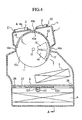
- Figure 4 is a cross sectional view showing this air regulator for vehicles
- Figure 5 is a cross sectional view taken along the line A - A in Figure 4
- Figure 6 is a view taken along the B - B arrows in Figure 5
- Figure 7 is an angle view showing the blowout mode changeover damper.
- An evaporator 4, a heater 5, an air mix damper 6, a blowout mode changeover damper 10, and the like are disposed within a casing 1 which is provided within the center console.
- the evaporator 4 is affixed to the bottom portion of the casing 1 in such a posture as to angle upwards gradually in the direction of the air intake port 25.
- the heater 5 is provided so as to be slightly angled at a position to one side within the casing 1.
- the air mix damper 6 is a slide type air mix damper and is provided on the downstream side of the evaporator 4 and on the upstream side of heater 5 so as to be in close proximity thereto.
- a pair of racks 100 are provided in a parallel manner at the bottom surface of the air mix damper 6 so as to maintain a gap therebetween, and pinions 101, 101 which engage with this pair of racks 100 are affixed to a rotational axle 102.
- This rotational axle 102 is accepted by the left and right side walls 1b, 1c of casing 1 via bearings and the like, and gears 103 which are affixed to the projecting ends thereof engage with teeth 107 which are formed on the outer circumference of a drive plate 104.
- drive plate 104 rotates about the axle 106, and in accordance with this, the air mix damper 6 is driven via gears 103, rotational axle 102, pinions 101 and racks 100, and is caused to slide in a direction perpendicular to the direction of air flow, guided in guide 26.
- Drive plate 104 may be rotated by hand about axle 106 instead of being driven by motor 105.
- Blowout mode changeover damper 10 is provided in the air mix region above heater 5 so as to be freely rotatable about a rotational axle 15.
- this damper 10 has the overall shape of a hollow barrel, and on the cylindrical part 10a thereof, a defrost exit 12, a face exit 13, and an inlet 11 which is in constant communication with the air mix region, are formed with predetermined gaps therebetween in the circumferencial direction, and fan shaped foot exits 14 are formed in the side walls 10b and 10c thereof, and a rotational axle 15 is provided in the center thereof.
- This rotational axle 15 is accepted by the left and right side walls 1b and 1c of the casing 1.
- partitions 16a, 16b, and 16c which form seals by close contact with the outer surface of cylindrical part 10a with a predetermined spacing in the circumferencial direction thereof, are formed in casing 1.
- a face blowout port 2 is formed in the upper surface 1a of casing 1 so as to be positioned between projections 16a and 16b, and a defrost blowout port 3 is also therein to so as to be positioned between projections 16b and 16c, and foot blowout ports 19 are formed on the left and right side walls 1b and 1c of casing 1 so as to engage with foot exits 14.
- a face duct 21, which communicates with face blowout port 2, a defrost duct 22, which communicates with defrost blowout port 3, and a foot duct 23, which communicates with foot blowout port 19, are coupled.
- the air within the vehicle and/or external air which is motivated by a blower not depicted, enters casing 1 from air intake port 25, and in the process of passing through evaporator 4, this air is cooled by means of heat exchange with a cooling medium.
- air mix damper 6 The flow of this air is split by air mix damper 6; the air flowing on the right side of air mix damper 6 enters heater 5 and is heated by means of heat exchange with engine coolant, and after this is combined with air flowing through a bypass path 27 formed on the left side of air mix damper 6, and becomes air regulated at a specified temperature.
- This regulated air passes through the intake port 11 of blowout mode changeover damper 10, and is blown out from one or two of the blowout ports 2, 3, and 19, which are selected by means of rotating damper 10 about rotational axle 15.
- damper 10 When damper 10 is rotated slightly in a counter clockwise direction in Figure 3, face exit 13 is partially sealed, and face exit 14 partially engages with foot blowout port 19, so that a portion of the regulated air is blown out of the face blowout port 2, while the remainder simultaneously passes through foot exit 14, foot blowout port 19, and foot duct 23 and is blown out in the direction of the feet of the passengers of the vehicle.
- damper 10 When damper 10 is further rotated in a counter clockwise direction, the communication between face exit 13 and face blowout port 2 is cut off, and only foot exit 14 engages with foot blowout port 19, so that the regulated air is blown solely out of the foot blowout port 19.
- defrost exit 12 When damper 10 is further rotated, foot exit 14 and foot blowout port 19 are partially engaged, and defrost exit 12 partially communicates with defrost blowout port 3, so that a portion of the regulated air is blown out of the foot blowout port 19, while simultaneously, the remainder of the regulated air passes through defrost exit 12, defrost blowout port 3, and defrost duct 22, and is blown out in the direction of the interior surface of the windshield and the like.
- the air mix damper 6 is on the downstream side of the evaporator 4, and is installed on the upstream side of heater 5 and is in close proximity therewith, so that the upper surface thereof is heated by the radiation from the heater 5, and the lower surface thereof is cooled by the air flowing through the evaporator 4.
- air mix damper 6 is upwardly thermally deformed in a convex manner as a result of the difference in temperature between the upper and lower surfaces thereof, and the racks 100 cease to engage with the pinions 101, so that it becomes impossible to slide the air mix damper 6.
- the present invention solves the problems described above; it comprises an air regulator for vehicles which is provided with, in a casing: an evaporator, which cools air; a heater, which reheats the air cooled by the evaporator; and an air mix damper, which is disposed on the downstream side of the evaporator and on the upstream side of the heater and in close proximity thereto, and which regulates the amount of air flowing through the heater; and in which a heat reflecting surface is formed on the heater side of the air mix damper.
- a heat reflecting surface is formed on the heater side of the air mix damper, so that the radiation from the heater side is reflected by the heat reflecting surface, and it is thus possible to prevent the thermal deformation of the air mix damper. Accordingly, the sliding problems of the air mix damper can be prevented.
- Figure 1 is a cross sectional view showing an embodiment of the air regulator for vehicles of the present invention.
- Figure 2 is an angle view showing the air mix damper of an embodiment of the present invention.
- Figure 3 shows the relationship between the amount of deformation of the air mix damper and the temperature of the heater.
- Figure 4 is a cross sectional view showing a conventional air regulator for vehicles.
- Figure 5 is a cross sectional view taken along the line A - A of Figure 4.
- Figure 6 is a view taken along the arrows of the B - B line in Figure 5.
- Figure 7 is an angle view showing the blowout mode changeover damper of a conventional air regulator for vehicles.
- Figure 1 is a cross sectional view showing this air regulator for vehicles, while Figure 2 is an angled view showing the air mix damper of this device; Figure 1 corresponds to Figure 4, which shows a conventional device.
- a heat reflecting surface 116 comprising a polished metal surface or the like is formed at the upper surface of the air mix damper 6 of this device at the side of the heater 5.
- This heat reflecting surface 116 is formed either by applying a material having a high heat reflection ratio to the upper surface on the side of heater 5, or by conducting surface treatment such as metallic plating treatment or the like on the upper surface.
- Metal leaf such as aluminum leaf or the like, or metallic plate such as thin aluminum plate or the like, may be preferentially employed as the material having a high heat reflection ratio.
- the radiation from heater 5 is reflected by the heat reflecting surface 116 formed on the upper surface of air mix damper 6 at the side of heater 5, so that the temperature increase of the upper surface of air mix damper 6 is controlled, and accordingly, it is possible to prevent the thermal deformation of air mix damper 6.
- Figure 3 shows the relationship between the temperature of heater 5 and the amount of deformation of the air mix damper 6, both with respect to the present invention and the conventional technology; the region S in the figure shows the range of operational suitability.
- the conventional device B comprising a black colored resin surface
- the conventional device C comprising a brown colored resin surface
Landscapes
- Physics & Mathematics (AREA)
- Thermal Sciences (AREA)
- Engineering & Computer Science (AREA)
- Mechanical Engineering (AREA)
- Air-Conditioning For Vehicles (AREA)
- Filling Or Discharging Of Gas Storage Vessels (AREA)
Claims (7)
- Luftregler für Fahrzeuge, der in einem Gehäuse Folgendes aufweist: einen Verdampfer, der Luft kühlt; ein Heizgerät, das die vom Verdampfer gekühlte Luft wieder erwärmt; und eine Luftmischklappe, die an der stromabwärtigen Seite des Verdampfers und an der stromaufwärtigen Seite des Heizgeräts und in dessen unmittelbarer Nähe angeordnet ist, und die die durch das Heizgerät strömende Luftmenge regelt,
dadurch gekennzeichnet, dass
eine Wärme reflektierende Oberfläche ausgeformt wird, indem ein Material mit einem hohen Wärmereflexionsverhältnis auf der heizgerätseitigen Oberfläche der Luftmischklappe aufgebracht wird, um eine Wärmeverformung derselben zu verhindern. - Luftregler für Fahrzeuge gemäß Anspruch 1,
dadurch gekennzeichnet, dass
das Material entweder aus Metallblattmaterial oder Metallblech besteht. - Luftregler für Fahrzeuge gemäß Anspruch 2,
dadurch gekennzeichnet, dass
das Metallblattmaterial Aluminiumblattmaterial aufweist. - Luftregler für Fahrzeuge gemäß Anspruch 2,
dadurch gekennzeichnet, dass
das Metallblech Aluminiumblech aufweist. - Luftregler für Fahrzeuge gemäß Anspruch 1,
dadurch gekennzeichnet, dass
die Wärme reflektierende Oberfläche durch Oberflächenbehandlung der Oberfläche der Luftmischklappe an der Seite des Heizgeräts gebildet wird. - Luftregler für Fahrzeuge gemäß Anspruch 1,
dadurch gekennzeichnet, dass
die Oberflächenbehandlung eine Metallbeschichtungsbehandlung aufweist. - Luftregler für Fahrzeuge gemäß Anspruch 1,
dadurch gekennzeichnet, dass
die Luftmischklappe eine Luftmischklappe des Gleittyps aufweist.
Applications Claiming Priority (3)
| Application Number | Priority Date | Filing Date | Title |
|---|---|---|---|
| JP9122841A JPH10297246A (ja) | 1997-04-28 | 1997-04-28 | 車両用空気調和装置 |
| JP12284197 | 1997-04-28 | ||
| JP122841/97 | 1997-04-28 |
Publications (3)
| Publication Number | Publication Date |
|---|---|
| EP0875406A2 EP0875406A2 (de) | 1998-11-04 |
| EP0875406A3 EP0875406A3 (de) | 2000-03-29 |
| EP0875406B1 true EP0875406B1 (de) | 2002-03-06 |
Family
ID=14845964
Family Applications (1)
| Application Number | Title | Priority Date | Filing Date |
|---|---|---|---|
| EP98107890A Expired - Lifetime EP0875406B1 (de) | 1997-04-28 | 1998-04-27 | Luftregler für Kraftfahrzeuge |
Country Status (10)
| Country | Link |
|---|---|
| US (1) | US5899806A (de) |
| EP (1) | EP0875406B1 (de) |
| JP (1) | JPH10297246A (de) |
| KR (1) | KR100299505B1 (de) |
| CN (1) | CN1108937C (de) |
| AU (1) | AU704017B2 (de) |
| CA (1) | CA2235839C (de) |
| DE (1) | DE69804045T2 (de) |
| ES (1) | ES2173524T3 (de) |
| TW (1) | TW390849B (de) |
Families Citing this family (31)
| Publication number | Priority date | Publication date | Assignee | Title |
|---|---|---|---|---|
| WO1998034805A1 (en) | 1997-02-06 | 1998-08-13 | Calsonic Corporation | Door mechanism for automobile air conditioner |
| JP2000238525A (ja) * | 1998-12-25 | 2000-09-05 | Denso Corp | 車両用空調装置 |
| KR100559183B1 (ko) * | 1998-12-31 | 2006-05-29 | 한라공조주식회사 | 차량용공조장치의템프도어 |
| US6453991B1 (en) | 1999-03-29 | 2002-09-24 | Calsonickansei Corporation | Automotive air conditioner |
| JP4166393B2 (ja) * | 1999-04-13 | 2008-10-15 | カルソニックカンセイ株式会社 | 自動車用空気調和装置のドア駆動用歯車 |
| JP4084911B2 (ja) | 1999-08-23 | 2008-04-30 | カルソニックカンセイ株式会社 | 自動車用空気調和装置 |
| EP1092572B1 (de) * | 1999-10-14 | 2005-12-07 | Calsonic Kansei Corporation | Schiebetüreinheit einer Kraftfahrzeug-Klimaanlage |
| DE10012975C1 (de) * | 2000-03-16 | 2001-03-08 | Daimler Chrysler Ag | Heizungs- oder Klimaanlage |
| US6736190B2 (en) * | 2001-04-03 | 2004-05-18 | Denso Corporation | Vehicle air conditioner |
| KR20030047362A (ko) * | 2001-12-10 | 2003-06-18 | 현대자동차주식회사 | 자동차의 공조장치 |
| CN1248877C (zh) * | 2001-12-11 | 2006-04-05 | 株式会社电装 | 具有旋转风门的汽车空调器 |
| JP4089390B2 (ja) | 2002-11-05 | 2008-05-28 | 株式会社デンソー | 車両用空調装置 |
| US7766078B2 (en) | 2003-01-11 | 2010-08-03 | Halla Climate Control Corp. | Mode door for the automotive vehicle air conditioning system |
| JP4147949B2 (ja) * | 2003-01-23 | 2008-09-10 | 株式会社デンソー | 空気通路開閉装置および車両用空調装置 |
| JP3841063B2 (ja) * | 2003-04-25 | 2006-11-01 | 株式会社デンソー | 空気通路開閉装置および車両用空調装置 |
| KR100958423B1 (ko) | 2003-05-29 | 2010-05-18 | 한라공조주식회사 | 도어조립체 |
| EP1634736B1 (de) | 2003-06-09 | 2009-07-29 | Valeo Thermal Systems Japan Corporation | Schiebetürvorrichtung für klimaanlage |
| US6899614B1 (en) * | 2003-12-08 | 2005-05-31 | Behr Gmbh & Co. | Ventilation unit for a motor vehicle |
| US7527551B2 (en) | 2004-08-27 | 2009-05-05 | Delphi Technologies, Inc. | Sliding valve, especially for heating, ventilation and air conditioning system |
| US7371161B2 (en) * | 2004-08-27 | 2008-05-13 | Delphi Technologies, Inc. | Sliding film valve driven at edge |
| KR101220968B1 (ko) * | 2006-07-24 | 2013-01-10 | 한라공조주식회사 | 차량용 공조장치의 온도조절도어 조립구조 |
| JP4596046B2 (ja) * | 2008-06-19 | 2010-12-08 | 株式会社デンソー | 空気通路開閉装置 |
| US8721408B2 (en) * | 2009-11-18 | 2014-05-13 | Keihin Corporation | Air conditioner for vehicle |
| US8840452B2 (en) * | 2010-04-27 | 2014-09-23 | Halla Visteon Climate Control Corporation | Air conditioner for vehicle |
| JP2012002335A (ja) * | 2010-06-21 | 2012-01-05 | Keihin Corp | スライドドア装置 |
| KR101571905B1 (ko) * | 2010-10-04 | 2015-11-26 | 현대자동차주식회사 | 자동차의 보조 냉난방장치 |
| CN111002787B (zh) * | 2018-10-08 | 2023-04-11 | 翰昂汽车零部件有限公司 | 带贯通孔的部件及具备该部件的车辆用空调装置 |
| CN112440679B (zh) * | 2019-08-31 | 2023-01-06 | 比亚迪股份有限公司 | 车辆的空调出风结构、车辆空调系统及车辆 |
| US11718150B2 (en) * | 2021-05-26 | 2023-08-08 | Valeo North America, Inc. | Heating ventilation and air-conditioning system with an intermediate door |
| WO2023071263A1 (zh) * | 2021-10-29 | 2023-05-04 | 青岛海尔空调器有限总公司 | 导风板组件及用于控制导风板组件的方法、处理系统 |
| CN116123686B (zh) * | 2021-11-12 | 2025-12-19 | 青岛海尔空调器有限总公司 | 一种导风板与面板之间间隙的控制方法及组件 |
Family Cites Families (10)
| Publication number | Priority date | Publication date | Assignee | Title |
|---|---|---|---|---|
| DE1192537B (de) * | 1960-03-12 | 1965-05-06 | Firth Cleveland Ltd | Vorrichtung zur Belueftung und/oder Beheizung von Fahrzeugkabinen |
| SE8001514L (sv) * | 1980-02-27 | 1981-08-28 | Saab Scania Ab | Uppvermnings- och ventilationssytem for fordon |
| DE3211148C2 (de) * | 1982-03-26 | 1984-05-03 | Ford-Werke AG, 5000 Köln | Heizungs- und Belüftungsanlage für Kraftfahrzeuge |
| DE3536133A1 (de) * | 1985-10-10 | 1987-04-16 | Bosch Gmbh Robert | Waermestrahlungssensor |
| CN2057271U (zh) * | 1989-07-30 | 1990-05-16 | 瓯海县工矿机械厂 | 多功能冷暖风机 |
| DE4120093A1 (de) * | 1991-06-18 | 1992-12-24 | Lindner Ag | Heiz- und/oder kuehlvorrichtung fuer den fahrgastraum eines fahrzeugs |
| EP0545320B1 (de) * | 1991-11-29 | 1997-01-29 | Nippondenso Co., Ltd. | Luftwege-Umschaltvorrichtung |
| JPH06328927A (ja) * | 1993-05-21 | 1994-11-29 | Nippondenso Co Ltd | 開閉装置 |
| CN2198547Y (zh) * | 1994-02-02 | 1995-05-24 | 青岛市崂山区东李稳压设备厂 | 换气供热两用机 |
| JP3510368B2 (ja) | 1995-01-31 | 2004-03-29 | 東燃ゼネラル石油株式会社 | 内燃機関用潤滑油組成物 |
-
1997
- 1997-04-28 JP JP9122841A patent/JPH10297246A/ja not_active Withdrawn
-
1998
- 1998-04-10 US US09/058,179 patent/US5899806A/en not_active Expired - Fee Related
- 1998-04-24 CA CA002235839A patent/CA2235839C/en not_active Expired - Fee Related
- 1998-04-27 ES ES98107890T patent/ES2173524T3/es not_active Expired - Lifetime
- 1998-04-27 EP EP98107890A patent/EP0875406B1/de not_active Expired - Lifetime
- 1998-04-27 TW TW087106444A patent/TW390849B/zh not_active IP Right Cessation
- 1998-04-27 AU AU63627/98A patent/AU704017B2/en not_active Ceased
- 1998-04-27 DE DE69804045T patent/DE69804045T2/de not_active Expired - Fee Related
- 1998-04-28 CN CN98115110A patent/CN1108937C/zh not_active Expired - Fee Related
- 1998-04-28 KR KR1019980015205A patent/KR100299505B1/ko not_active Expired - Fee Related
Also Published As
| Publication number | Publication date |
|---|---|
| EP0875406A2 (de) | 1998-11-04 |
| AU6362798A (en) | 1998-10-29 |
| KR100299505B1 (ko) | 2001-10-19 |
| CA2235839C (en) | 2002-07-16 |
| DE69804045T2 (de) | 2002-08-22 |
| ES2173524T3 (es) | 2002-10-16 |
| DE69804045D1 (de) | 2002-04-11 |
| EP0875406A3 (de) | 2000-03-29 |
| US5899806A (en) | 1999-05-04 |
| JPH10297246A (ja) | 1998-11-10 |
| CA2235839A1 (en) | 1998-10-28 |
| AU704017B2 (en) | 1999-04-01 |
| CN1199675A (zh) | 1998-11-25 |
| CN1108937C (zh) | 2003-05-21 |
| TW390849B (en) | 2000-05-21 |
| KR19980081813A (ko) | 1998-11-25 |
Similar Documents
| Publication | Publication Date | Title |
|---|---|---|
| EP0875406B1 (de) | Luftregler für Kraftfahrzeuge | |
| EP1078791B1 (de) | Kraftfahrzeug-Klimaanlage | |
| US6463998B1 (en) | Vehicle air conditioning ventilation system and apparatus having positional doors and blow-switching modes | |
| US5701949A (en) | Air conditioner for an automobile | |
| US5934989A (en) | Air conditioning apparatus for vehicle | |
| EP1070611B1 (de) | Klimatisierungseinheit einer fahrzeugklimaanlage | |
| US5335718A (en) | Space-efficient air conditioning/heating module | |
| JP3758262B2 (ja) | 空気調和装置 | |
| US5632672A (en) | Air conditioning apparatus with film member | |
| EP0993974B1 (de) | Luft-Handhabungssystem für Kraftfahrzeuge | |
| US6079484A (en) | Air conditioning apparatus for vehicle | |
| US7478666B2 (en) | Vehicle air conditioner | |
| US5964658A (en) | Air passage opening/closing system for air conditioning apparatus | |
| GB2300043A (en) | Air-conditioning system for a vehicle | |
| US6568200B2 (en) | Air-conditioning system for a vehicle | |
| US6920921B2 (en) | Air conditioner for vehicles with right steering wheel and left steering wheel | |
| EP1835827A1 (de) | Luftsteuerungstür mit integrierter schichtungsfunktion | |
| EP1437243B1 (de) | Ventilsitze für Ventilfolien | |
| GB2329465A (en) | Air conditioner for vehicle | |
| US6877550B2 (en) | Vehicle air conditioner | |
| JP3873433B2 (ja) | 車両用空調装置 | |
| JP3692636B2 (ja) | 車両用空調装置 | |
| JPH11198629A (ja) | 車両用空調装置 | |
| JPH0345846Y2 (de) | ||
| JP3637679B2 (ja) | 車両用空調装置 |
Legal Events
| Date | Code | Title | Description |
|---|---|---|---|
| PUAI | Public reference made under article 153(3) epc to a published international application that has entered the european phase |
Free format text: ORIGINAL CODE: 0009012 |
|
| 17P | Request for examination filed |
Effective date: 19980427 |
|
| AK | Designated contracting states |
Kind code of ref document: A2 Designated state(s): BE DE ES FR GB NL |
|
| AX | Request for extension of the european patent |
Free format text: AL;LT;LV;MK;RO;SI |
|
| PUAL | Search report despatched |
Free format text: ORIGINAL CODE: 0009013 |
|
| AK | Designated contracting states |
Kind code of ref document: A3 Designated state(s): AT BE CH CY DE DK ES FI FR GB GR IE IT LI LU MC NL PT SE |
|
| AX | Request for extension of the european patent |
Free format text: AL;LT;LV;MK;RO;SI |
|
| AKX | Designation fees paid |
Free format text: BE DE ES FR GB NL |
|
| 17Q | First examination report despatched |
Effective date: 20001115 |
|
| GRAG | Despatch of communication of intention to grant |
Free format text: ORIGINAL CODE: EPIDOS AGRA |
|
| GRAG | Despatch of communication of intention to grant |
Free format text: ORIGINAL CODE: EPIDOS AGRA |
|
| GRAH | Despatch of communication of intention to grant a patent |
Free format text: ORIGINAL CODE: EPIDOS IGRA |
|
| GRAH | Despatch of communication of intention to grant a patent |
Free format text: ORIGINAL CODE: EPIDOS IGRA |
|
| REG | Reference to a national code |
Ref country code: GB Ref legal event code: IF02 |
|
| GRAA | (expected) grant |
Free format text: ORIGINAL CODE: 0009210 |
|
| AK | Designated contracting states |
Kind code of ref document: B1 Designated state(s): BE DE ES FR GB NL |
|
| REF | Corresponds to: |
Ref document number: 69804045 Country of ref document: DE Date of ref document: 20020411 |
|
| ET | Fr: translation filed | ||
| REG | Reference to a national code |
Ref country code: ES Ref legal event code: FG2A Ref document number: 2173524 Country of ref document: ES Kind code of ref document: T3 |
|
| PLBE | No opposition filed within time limit |
Free format text: ORIGINAL CODE: 0009261 |
|
| STAA | Information on the status of an ep patent application or granted ep patent |
Free format text: STATUS: NO OPPOSITION FILED WITHIN TIME LIMIT |
|
| 26N | No opposition filed |
Effective date: 20021209 |
|
| PGFP | Annual fee paid to national office [announced via postgrant information from national office to epo] |
Ref country code: NL Payment date: 20040406 Year of fee payment: 7 |
|
| PGFP | Annual fee paid to national office [announced via postgrant information from national office to epo] |
Ref country code: FR Payment date: 20040408 Year of fee payment: 7 |
|
| PGFP | Annual fee paid to national office [announced via postgrant information from national office to epo] |
Ref country code: ES Payment date: 20040416 Year of fee payment: 7 |
|
| PGFP | Annual fee paid to national office [announced via postgrant information from national office to epo] |
Ref country code: GB Payment date: 20040421 Year of fee payment: 7 |
|
| PGFP | Annual fee paid to national office [announced via postgrant information from national office to epo] |
Ref country code: BE Payment date: 20040617 Year of fee payment: 7 |
|
| PGFP | Annual fee paid to national office [announced via postgrant information from national office to epo] |
Ref country code: DE Payment date: 20050421 Year of fee payment: 8 |
|
| PG25 | Lapsed in a contracting state [announced via postgrant information from national office to epo] |
Ref country code: GB Free format text: LAPSE BECAUSE OF NON-PAYMENT OF DUE FEES Effective date: 20050427 |
|
| PG25 | Lapsed in a contracting state [announced via postgrant information from national office to epo] |
Ref country code: ES Free format text: LAPSE BECAUSE OF NON-PAYMENT OF DUE FEES Effective date: 20050428 |
|
| PG25 | Lapsed in a contracting state [announced via postgrant information from national office to epo] |
Ref country code: BE Free format text: LAPSE BECAUSE OF NON-PAYMENT OF DUE FEES Effective date: 20050430 |
|
| BERE | Be: lapsed |
Owner name: *MITSUBISHI HEAVY INDUSTRIES LTD Effective date: 20050430 |
|
| PG25 | Lapsed in a contracting state [announced via postgrant information from national office to epo] |
Ref country code: NL Free format text: LAPSE BECAUSE OF NON-PAYMENT OF DUE FEES Effective date: 20051101 |
|
| GBPC | Gb: european patent ceased through non-payment of renewal fee |
Effective date: 20050427 |
|
| PG25 | Lapsed in a contracting state [announced via postgrant information from national office to epo] |
Ref country code: FR Free format text: LAPSE BECAUSE OF NON-PAYMENT OF DUE FEES Effective date: 20051230 |
|
| NLV4 | Nl: lapsed or anulled due to non-payment of the annual fee |
Effective date: 20051101 |
|
| REG | Reference to a national code |
Ref country code: FR Ref legal event code: ST Effective date: 20051230 |
|
| REG | Reference to a national code |
Ref country code: ES Ref legal event code: FD2A Effective date: 20050428 |
|
| PG25 | Lapsed in a contracting state [announced via postgrant information from national office to epo] |
Ref country code: DE Free format text: LAPSE BECAUSE OF NON-PAYMENT OF DUE FEES Effective date: 20061101 |
|
| BERE | Be: lapsed |
Owner name: *MITSUBISHI HEAVY INDUSTRIES LTD Effective date: 20050430 |