EP0875442A2 - Système de fixation de toit pour cabine de tracteur - Google Patents
Système de fixation de toit pour cabine de tracteur Download PDFInfo
- Publication number
- EP0875442A2 EP0875442A2 EP98303477A EP98303477A EP0875442A2 EP 0875442 A2 EP0875442 A2 EP 0875442A2 EP 98303477 A EP98303477 A EP 98303477A EP 98303477 A EP98303477 A EP 98303477A EP 0875442 A2 EP0875442 A2 EP 0875442A2
- Authority
- EP
- European Patent Office
- Prior art keywords
- roll bar
- canopy
- attachment
- attachment frame
- substantially horizontal
- Prior art date
- Legal status (The legal status is an assumption and is not a legal conclusion. Google has not performed a legal analysis and makes no representation as to the accuracy of the status listed.)
- Withdrawn
Links
- 238000009434 installation Methods 0.000 description 4
- 230000034994 death Effects 0.000 description 2
- 231100000517 death Toxicity 0.000 description 2
- 239000011152 fibreglass Substances 0.000 description 2
- 238000000034 method Methods 0.000 description 2
- 229910000831 Steel Inorganic materials 0.000 description 1
- 238000010276 construction Methods 0.000 description 1
- 230000006378 damage Effects 0.000 description 1
- 230000000694 effects Effects 0.000 description 1
- 239000000463 material Substances 0.000 description 1
- 239000002991 molded plastic Substances 0.000 description 1
- 230000001681 protective effect Effects 0.000 description 1
- 230000000284 resting effect Effects 0.000 description 1
- 239000010959 steel Substances 0.000 description 1
- 238000003466 welding Methods 0.000 description 1
Images
Classifications
-
- B—PERFORMING OPERATIONS; TRANSPORTING
- B62—LAND VEHICLES FOR TRAVELLING OTHERWISE THAN ON RAILS
- B62D—MOTOR VEHICLES; TRAILERS
- B62D33/00—Superstructures for load-carrying vehicles
- B62D33/06—Drivers' cabs
- B62D33/0617—Drivers' cabs for tractors or off-the-road vehicles
- B62D33/0625—Drivers' cabs for tractors or off-the-road vehicles open
Definitions
- the present invention relates to a canopy attachment system in particular for an agricultural tractor equipped with a roll bar.
- the present invention is directed to a tractor canopy attachment system which includes a pair of vertical mounting brackets which are attachable to respective upright posts of a tractor roll bar and a horizontal mounting bracket which is attachable to a horizontal bar on the roll bar.
- the horizontal mounting bracket includes a mounting flange extending upward therefrom.
- An attachment frame connected to the canopy includes a cross member attached to a bottom side of the canopy near the rear thereof.
- a mounting flange receiver is attached to an upper side of the cross member near the center thereof, which receiver cooperates with the mounting flange on the horizontal mounting bracket to hold the canopy in place on the roll bar.
- a pair of angled braces are attached near respective ends of the frame cross member, with each brace including a vertical support arm attached to and extending downward from the cross member to a position in which it is removably attachable to a respective one of the vertical mounting brackets.
- Each brace also includes an angled support arm which is attached to and extends forward and upward at an angle from the vertical support arm, with a terminal end of the angled support arm being attached to the bottom side of the canopy forward of the point of attachment of the cross member.
- a plurality of easily removable pins hold the mounting flange receiver in position on the mounting flange and a single pin holds each angled brace in position on its respective vertical mounting bracket.
- the principal objects of the present invention are: to provide an improved canopy attachment system for an agricultural tractor; to provide such a system in which a number of support brackets are removably attached to a tractor roll bar; to provide such a system in which a canopy attachment frame is attached to the bottom side of the canopy; to provide such a system in which the attachment frame is removably held in place on the roll bar by the support brackets; to provide such a system in which the canopy is latched in place on the roll bar by easily removable pins; to provide such a system which allows a lone operator to install or remove a canopy within a few minutes; to provide such a system which is ideal for installation on hinged tractor roll bars; and to provide such a system which is particularly well adapted for its intended purpose.
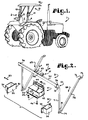
- Fig. 1 is a perspective view of an agricultural tractor equipped with a hinged roll bar with a canopy attached via the inventive canopy attachment system.
- Fig. 2 is a greatly enlarged, exploded view of the inventive canopy attachment system.
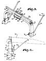
- Fig. 3 is a greatly enlarged, fragmentary, perspective view of an upper portion of a tractor roll bar, with the inventive canopy attachment system mounted thereon, but with the canopy removed for ease of illustration.
- Fig. 4 is a fragmentary, side elevational view of an upper portion of the roll bar of Fig. 3, with the inventive canopy attachment system mounted thereon, and with the canopy shown in phantom lines.
- an agricultural tractor generally indicated at 1, includes a roll bar, generally indicated at 2.
- the roll bar 2 includes left and right upright supports 3 and 4, respectively, with a horizontal bar 5 (Fig. 3) extending therebetween and generally positioned above an operators position 11.
- each upright support 3 and 4 comprises an upper section 12 and a lower section 13, which are attached to each other via a locking hinge 14.
- Each locking hinge 14 includes upper and lower, generally triangularly shaped hinge plate pairs 15 and 16, respectively, which are hingedly attached to each other via sleeves 21 on a common axis and a pivot pin 22 extending through the sleeves 21.
- Each upper plate pair 15 is attached to a respective upper support section 12 and each lower plate pair 16 is attached to a respective lower support section 13 such that the hinge 14 allows the upper support sections 12 to be pivoted backward and folded down to allow the roll bar 2 to be folded approximately in half.
- a locking bolt or pin 23 is inserted through sleeves 24 in the plate pairs 15 and 16 to lock the roll bar 2 in the upper position.
- hinged roll bar is conventional, and is merely representative of a number of different hinged roll bars.
- the present invention is usable with any tractor roll bar configuration, whether hinged or not.
- the canopy attachment system is generally indicated at 31.
- the system 31 includes a pair of vertical mounting brackets 32, each of which includes a plate 33 and a generally U shaped member 34.
- Each bracket 32 is attachable on a respective upright support 3 or 4 of the roll bar 2 by placing the U shaped member 34 around the upright support 3 or 4 from the outside thereof.
- the plate 33 is then bolted to the U shaped member 34 via bolts 35 extending through aligned apertures 36 to thereby clamp each vertical mounting bracket 32 in position on the respective support 3 or 4.
- the system 31 also includes a horizontal mounting bracket 41, which includes a first generally L shaped angle member 42 which is sized and shaped to abut and overlap both a front surface and a bottom surface of the horizontal bar 5 of the roll bar 2.
- the bracket 41 also includes a second, generally L shaped angle member 43 which is sized and shaped to abut and overlap both a rear surface and a top surface of the horizontal bar 5 of the roll bar 2.
- the member 43 also includes a flange 44 which extends upward and a flange 45 which extends rearward, with the flanges 44 and 45 being attachable to respective legs of the first angle member 43 via a plurality of bolts 46 extending through aligned apertures 47 to thereby clamp the bracket 41 about the roll bar horizontal bar 5, as shown in Fig. 3.
- the first angle member 42 also includes an extension which extends upward past the second angle member 43 and rearward at a slight angle from vertical to form a mounting flange 48.
- the mounting flange 48 includes a pair of through bores 51, whose purpose will be explained below.
- the mounting system 31 includes a canopy attachment frame, generally indicated at 53, which frame 53 includes a cross member 54, which may be made of steel tubing with a square cross section, for example.
- the cross member 54 is attachable to a bottom surface of a canopy 55 near the rear thereof via mounting apertures 56 such that the cross member 54 is positioned beneath the canopy 55.
- a mounting flange 61 is attached to the cross member 54 near the center thereof.
- the mounting flange 61 includes a generally flat leg 62 which is attached to the cross member 54, and a series of additional legs forming an inverted U shaped mounting flange receiver 63.
- the receiver 63 is sized and positioned at an angle such that it receives the angled extension 48 of the horizontal mounting bracket 41 when the cross member 54 is rested on the horizontal bar 5 of the roll bar 2, as is shown in Figs. 3 and 4.
- the cooperation of the mounting flange receiver 63 and the angled mounting flange 48 thus serve to hold the cross member 54 in place on the roll bar horizontal bar 5 during installation, as explained below.
- the receiver 63 also includes a pair of apertures 64 which are sized and positioned to match and correspond with the apertures 51 in the angled mounting flange 48.
- the mounting system canopy attachment frame 53 also includes a pair of angled braces 65 and 66, each of which includes a substantially vertical support arm 71 with an angled attachment leg 72. Each leg 72 is attached to a bottom side of the cross member 54 near a respective end thereof by welding or other suitable attachment techniques.
- Each angled brace 65 and 66 also includes an angled support arm 73 which includes a lower leg 74 which is attached to a lower end of the vertical support arm 71 and an upper leg 75 which is provided with a mounting aperture 76 for attachment to the canopy 55, as is generally indicated in Fig. 4.
- Each of the vertical support arms 71 includes a mounting aperture 81 extending side to side therethrough, which apertures 81 are positioned to align with corresponding apertures 82 on each of the vertical mounting brackets 32. While the angled braces 65 and 66 have been shown as constructed of interconnected arms 71 and 73, they can also be of a unitary construction with the same general shape.
- the canopy attachment frame 53 is first attached to the canopy 55 by bolting or otherwise attaching the angled support arms 65 and 66 and the cross member 54 to the underneath side of the canopy 55.
- the canopy 55 is conventional and can be made of laminated fiberglass or lighter weight molded plastic materials, for example.
- the horizontal support bracket 41 and the pair of vertical support brackets 32 are then clamped to the roll bar 2, as described above.
- Removal of the canopy 55 is easily and quickly accomplished by reversing the above procedure. First the pins 83 are removed from the apertures 81 and 82 and then from the through bores 64 and the apertures 51. The canopy 55 can then be simply lifted up and off of the roll bar 2. The vertical support brackets 32 and the horizontal support bracket 41 are simply left in place on the roll bar 2 pending the next installation of the canopy 55.
- the mounting flange 48 can be changed to a U shaped configuration to provide a more secure and stronger grip on the U shaped receiver 63.
- the illustrated cylindrical pins 83 cotter pins, threaded bolts or other removable securing members can be used as well.
- the particular angles and lengths of the components of the attachment system 31 are merely illustrative, and are readily adaptable to different roll bar configurations.
- the cross member 54 of the attachment frame 53 can include slots or multiple apertures extending vertically therethrough which allow the vertical support arms 71 to be adjusted along the length of the cross member 54 to adapt to different sizes and widths of tractor roll bars.
Landscapes
- Engineering & Computer Science (AREA)
- Chemical & Material Sciences (AREA)
- Combustion & Propulsion (AREA)
- Transportation (AREA)
- Mechanical Engineering (AREA)
- Body Structure For Vehicles (AREA)
- Agricultural Machines (AREA)
Applications Claiming Priority (2)
| Application Number | Priority Date | Filing Date | Title |
|---|---|---|---|
| US08/850,418 US5882063A (en) | 1997-05-02 | 1997-05-02 | Tractor canopy attachment system |
| US850418 | 1997-05-02 |
Publications (2)
| Publication Number | Publication Date |
|---|---|
| EP0875442A2 true EP0875442A2 (fr) | 1998-11-04 |
| EP0875442A3 EP0875442A3 (fr) | 1999-11-03 |
Family
ID=25308056
Family Applications (1)
| Application Number | Title | Priority Date | Filing Date |
|---|---|---|---|
| EP98303477A Withdrawn EP0875442A3 (fr) | 1997-05-02 | 1998-05-01 | Système de fixation de toit pour cabine de tracteur |
Country Status (3)
| Country | Link |
|---|---|
| US (1) | US5882063A (fr) |
| EP (1) | EP0875442A3 (fr) |
| CA (1) | CA2213158A1 (fr) |
Families Citing this family (13)
| Publication number | Priority date | Publication date | Assignee | Title |
|---|---|---|---|---|
| US6149228A (en) * | 1998-12-09 | 2000-11-21 | Deere & Company | Modular operator enclosure |
| US6471280B1 (en) | 2001-05-25 | 2002-10-29 | Bryan G. Fowler | Vehicle canopy system |
| US6915246B2 (en) * | 2001-12-17 | 2005-07-05 | International Business Machines Corporation | Employing speech recognition and capturing customer speech to improve customer service |
| US7182399B2 (en) * | 2003-08-27 | 2007-02-27 | Vicki C. Kamerer | Removable and adjustable sun shade for roll bar equipped vehicles |
| US7152903B2 (en) * | 2004-01-30 | 2006-12-26 | Westendorf Manufacturing Co., Inc. | Tractor, a canopy assembly, and a method for attaching a canopy assembly to a tractor |
| US7641234B1 (en) * | 2004-07-14 | 2010-01-05 | Femco, Inc. | Ride-on turf mowing machine rollover protection assembly |
| US8262149B1 (en) * | 2008-08-26 | 2012-09-11 | William Russ | Fan and canopy assembly for riding vehicle |
| US20100051729A1 (en) * | 2008-09-03 | 2010-03-04 | Agri-Fab, Inc. | Rear implement for a vehicle and method of exchanging rear implements |
| US9499034B1 (en) * | 2015-06-08 | 2016-11-22 | Deere & Company | Vehicle canopy |
| US9889727B2 (en) | 2016-05-31 | 2018-02-13 | Craig Thomas | Attachable canopy for riding lawnmower |
| US10053158B1 (en) * | 2016-08-03 | 2018-08-21 | Accu-Form Polymers, Inc. | Mount for canopies to go on generic rollover bars for riding lawn mowers and tractors |
| US11760420B1 (en) | 2021-01-21 | 2023-09-19 | Accuform Polymers, Inc. | Universal mounts for canopies to rollover protection bars of varied attitudes |
| CA227607S (en) * | 2023-07-21 | 2024-12-16 | S&A Group Holdings Ltd | Shielding for an agricultural robot |
Family Cites Families (26)
| Publication number | Priority date | Publication date | Assignee | Title |
|---|---|---|---|---|
| US869061A (en) * | 1907-05-13 | 1907-10-22 | Roy A Cox | Supporting-frame for canopies, awnings, &c. |
| US1251904A (en) * | 1916-08-23 | 1918-01-01 | John J Mamaux | Canopy. |
| US1465712A (en) * | 1922-11-20 | 1923-08-21 | Henry W Hanson | Top for tractors |
| US2785002A (en) * | 1954-07-26 | 1957-03-12 | Lawrence A Schumaker | Safety frame and top for tractor |
| US2921799A (en) * | 1958-02-24 | 1960-01-19 | Hatten Faith Pauline | Tractor safeguard |
| US3455598A (en) * | 1967-07-17 | 1969-07-15 | Deere & Co | Tractor roll bar and canopy |
| DE1948395C3 (de) * | 1969-09-25 | 1979-10-25 | Kloeckner-Humboldt-Deutz Ag, 5000 Koeln | Schlepperkabine |
| CH497300A (de) * | 1970-02-17 | 1970-10-15 | Schmid Adolf | Schutzvorrichtung für landwirtschaftliche Motorfahrzeuge |
| DE2019584C3 (de) * | 1970-04-23 | 1975-01-30 | Deere & Co., Moline, Ill. (V.St.A.) | Wetterschutz für Ackerschlepper |
| US3964782A (en) * | 1975-02-05 | 1976-06-22 | International Harvester Company | Interlocking welded construction for roll over protective structures |
| US4032187A (en) * | 1975-12-22 | 1977-06-28 | Allis-Chalmers Corporation | Energy absorbing joint for protective frame |
| US4049294A (en) * | 1975-12-22 | 1977-09-20 | Allis-Chalmers Corporation | Narrow base protective frame |
| US4102537A (en) * | 1976-06-18 | 1978-07-25 | Kubota Ltd. | Seated-operator type tractor |
| DE2647733A1 (de) * | 1976-10-22 | 1977-11-24 | Paul Erich Kettler | Vorrichtung zur lagerung und befestigung eines wetterverdeckes an einem schutzrahmen von schleppern, traktoren, bau- und dergleichen fahrzeugen |
| GB1522285A (en) * | 1977-02-02 | 1978-08-23 | White S | Safety frames for tractors |
| US4159835A (en) * | 1977-12-12 | 1979-07-03 | Allis-Chalmers Corporation | Vehicle protective frame with internal reinforcing members |
| US4184712A (en) * | 1978-05-16 | 1980-01-22 | J. I. Case Company | Enclosure mechanism for roll over protective structure |
| US4382613A (en) * | 1980-12-22 | 1983-05-10 | Allis-Chalmers Corporation | Deflectable support for protective frame |
| US4376550A (en) * | 1981-06-01 | 1983-03-15 | Paccar Inc. | Vehicle canopy |
| US4469114A (en) * | 1982-09-29 | 1984-09-04 | Orville Kelley | Canopy-removable, portable |
| US4666183A (en) * | 1986-01-14 | 1987-05-19 | J. I. Case Company | Roll-over protection device |
| DE3826392A1 (de) * | 1988-08-03 | 1990-02-15 | Deere & Co | Ueberschlagvorrichtung fuer ein fahrzeug |
| US5168889A (en) * | 1989-11-08 | 1992-12-08 | Diestel Daniel G | Wheelchair weather breaker cover |
| US5042835A (en) * | 1990-07-09 | 1991-08-27 | J. I. Case Company | Roll over protection apparatus |
| US5022420A (en) * | 1990-07-19 | 1991-06-11 | Brim Walter L | Lawn mower shade apparatus |
| JPH07186852A (ja) * | 1993-12-28 | 1995-07-25 | Kubota Corp | 農作業機の転倒保護構造 |
-
1997
- 1997-05-02 US US08/850,418 patent/US5882063A/en not_active Expired - Fee Related
- 1997-08-15 CA CA002213158A patent/CA2213158A1/fr not_active Abandoned
-
1998
- 1998-05-01 EP EP98303477A patent/EP0875442A3/fr not_active Withdrawn
Also Published As
| Publication number | Publication date |
|---|---|
| CA2213158A1 (fr) | 1998-11-02 |
| US5882063A (en) | 1999-03-16 |
| EP0875442A3 (fr) | 1999-11-03 |
Similar Documents
| Publication | Publication Date | Title |
|---|---|---|
| US5882063A (en) | Tractor canopy attachment system | |
| US5820002A (en) | Lockable bicycle rack | |
| US5224636A (en) | Utility rack | |
| US6533069B1 (en) | Multi-use ladder support apparatus | |
| US6502730B2 (en) | Carrier rack for vehicle | |
| US3528578A (en) | Motorcycle rack | |
| US5067641A (en) | Vehicle bicycle carrier | |
| AU721168B2 (en) | Vehicle racking system | |
| US6460745B1 (en) | Bicycle rack mounted to a vehicle trailer hitch sleeve | |
| US4084736A (en) | Vehicle mounted motorcycle rack | |
| US7513545B2 (en) | Moveable guard assembly for all terrain vehicle | |
| US4509769A (en) | Vehicle hitch | |
| US4744159A (en) | Readily detachable mounting for a wing plow | |
| US5081775A (en) | Plow attaching device and method | |
| US20100290876A1 (en) | Cargo Lift For All Terrain Vehicle | |
| US7118053B2 (en) | Mounting assembly for supporting a hopper and a spreading mechanism on a vehicle | |
| AU2006249121A1 (en) | Temporary safety barrier system | |
| US5876019A (en) | Winching apparatus for all-terrain vehicle | |
| US5116096A (en) | Truck cargo support outrigger | |
| US7168523B1 (en) | Mechanic's step with stirrup | |
| US6450379B1 (en) | Apparatus for supporting a load from a vehicle | |
| US5586743A (en) | Auger stand | |
| US20030201656A1 (en) | Removable rack assembly for holding ladders in a truck bed | |
| US8430286B1 (en) | Boat carrying rack for use on transporting vehicles | |
| US4548543A (en) | Quick attachment device |
Legal Events
| Date | Code | Title | Description |
|---|---|---|---|
| PUAI | Public reference made under article 153(3) epc to a published international application that has entered the european phase |
Free format text: ORIGINAL CODE: 0009012 |
|
| AK | Designated contracting states |
Kind code of ref document: A2 Designated state(s): AT BE CH CY DE DK ES FI FR GB GR IE IT LI LU MC NL PT SE |
|
| AX | Request for extension of the european patent |
Free format text: AL;LT;LV;MK;RO;SI |
|
| PUAL | Search report despatched |
Free format text: ORIGINAL CODE: 0009013 |
|
| AK | Designated contracting states |
Kind code of ref document: A3 Designated state(s): AT BE CH CY DE DK ES FI FR GB GR IE IT LI LU MC NL PT SE |
|
| AX | Request for extension of the european patent |
Free format text: AL;LT;LV;MK;RO;SI |
|
| RIC1 | Information provided on ipc code assigned before grant |
Free format text: 6B 62D 33/06 A, 6B 60R 21/13 B |
|
| AKX | Designation fees paid | ||
| REG | Reference to a national code |
Ref country code: DE Ref legal event code: 8566 |
|
| STAA | Information on the status of an ep patent application or granted ep patent |
Free format text: STATUS: THE APPLICATION IS DEEMED TO BE WITHDRAWN |
|
| 18D | Application deemed to be withdrawn |
Effective date: 20000504 |