EP0875645A1 - Einsteckschloss für den Einbau in eine Tür - Google Patents
Einsteckschloss für den Einbau in eine Tür Download PDFInfo
- Publication number
- EP0875645A1 EP0875645A1 EP98810020A EP98810020A EP0875645A1 EP 0875645 A1 EP0875645 A1 EP 0875645A1 EP 98810020 A EP98810020 A EP 98810020A EP 98810020 A EP98810020 A EP 98810020A EP 0875645 A1 EP0875645 A1 EP 0875645A1
- Authority
- EP
- European Patent Office
- Prior art keywords
- key
- cover
- lock
- mortise lock
- mortise
- Prior art date
- Legal status (The legal status is an assumption and is not a legal conclusion. Google has not performed a legal analysis and makes no representation as to the accuracy of the status listed.)
- Granted
Links
- 238000009434 installation Methods 0.000 claims description 3
- 238000002347 injection Methods 0.000 claims 1
- 239000007924 injection Substances 0.000 claims 1
- 239000002184 metal Substances 0.000 claims 1
- 238000000034 method Methods 0.000 description 2
- 229910000831 Steel Inorganic materials 0.000 description 1
- 239000000853 adhesive Substances 0.000 description 1
- 230000001070 adhesive effect Effects 0.000 description 1
- 239000011324 bead Substances 0.000 description 1
- 238000004519 manufacturing process Methods 0.000 description 1
- 239000010959 steel Substances 0.000 description 1
Images


Classifications
-
- E—FIXED CONSTRUCTIONS
- E05—LOCKS; KEYS; WINDOW OR DOOR FITTINGS; SAFES
- E05B—LOCKS; ACCESSORIES THEREFOR; HANDCUFFS
- E05B17/00—Accessories in connection with locks
- E05B17/0012—Accessories in connection with locks for lock parts held in place before or during mounting on the wing
Definitions
- the invention relates to a mortise lock for installation in a door according to the preamble of claim 1.
- Mortise locks for doors in living rooms are supplied together with an associated beard key or the like.
- the key that matches the lock must therefore always remain with the lock during delivery by the manufacturer to wholesalers, from there to retailers or joiners or door factories, since it is not externally visible which key matches the lock.
- handling problems arise, and keys can become detached from the corresponding mortise locks and get lost, and the corresponding door that matches the key must then be laboriously searched for. But even later when transporting the door, the associated key must always remain attached to the door. It is not possible to insert it into the keyhole as there is a latent risk of it falling out and getting lost.
- the object of the invention is now this Fix disadvantages and safe storage of the Key from the lock manufacturer until after the installation of the Ensure door in a residential or office building.
- the design of a free space within the Lock case or at least partially within the Lock case enables a safe and easy handling of the castle from the place of manufacture to the Destination in a building is not distracting Keep the key.
- the one attached to the forend Cover closes the storage space for the Key without having to insert the mortise lock in the door and the work processes when handling the lock disturb. These do not have to be compared to conventional to be changed.
- a very special advantage is that even after installing the door in one Building the key when it's not needed stored inside the castle and if necessary can be removed. The key can be found in the lower part the lock or inserted above the trap will.
- Lock case a container or a drawer trained in which the key is inserted and which after unlocking the cover on the cuff side Lock case can be pulled out.
- the key is fixed in a corresponding room in the lock case.
- the Cover can be part of the drawer or for the second and third embodiment is a separate part that inserted flush in the front of the cuff.
- the Locking for the cover is preferred designed tool-free, so that the Key removed or in the key holder can be covered.
- a spring in the lock case makes it easier to remove the key when it is in a container, drawer or unwrapped is kept. It must be when inserting the container or the drawer the spring, which is on the back of the lock case is pressed together. This bias is sufficient to after unlocking the Partially slide the cover out of the container.
- a container that is open on the side can hold the key already during the assembly of the lock case with the mechanical parts in them. An additional step is unnecessary and Confusion of the keys is impossible.
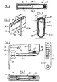
- the mortise lock 1 shown in Figure 1 includes a lock case 3 made of sheet steel or plastic, with a bottom 5, a lid 7 (lifted off in FIG. 1), three side walls 9 and a face plate 11.
- the face plate 11 dominates the lock case 3 above and below.
- faceplate 11 In faceplate 11 are recesses 13, 15 for the passage of the Lock latch 17 and a bolt 19 and holes 21 for attaching mortise lock 1 to a door 23 trained. How the mortise lock works 1 is known and is not explained in detail here.
- the key holder 27 can be all or only partly in lock case 3.
- the drawer 29 is the lower side wall 9 and is on the latter bent edges 31 which engage in grooves 33, longitudinally.
- the longitudinal guidance could of course also on specially designed rails (no illustration) take place when the drawer 29 the lock case 3 below not towered over.
- the drawer 29 is box-shaped trained and can be completely or partially open at the top.
- the drawer 29 is closed at the front and rear.
- the front wall forms a lid or cover 35, which lie flush with the surface of the cuff 11 comes when the drawer 29 is inserted.
- a Locking means e.g. one formed on the drawer 29 Spring 37 with a release tab accessible on the face plate 39, serves the drawer 29 within the Lock case 3 to hold on.
- To pull out the To facilitate drawer 29 is on the lock case 3 or attached to the drawer 29 a spring 41 which at Retracting is tensioned and when releasing the locking means Ejects drawer 29.
- the drawer 29 is just large enough for the key belonging to mortise lock 3 43 record.
- the key 43 is located directly in the Lock case 3, which serves as a key holder 27.
- the Cover 35 is designed as a flap and presses the Key 43 against the force of the spring 41 to the rear.
- Pivot axis B pivotable cover 35 is used.
- the Swivel axis B is, for example, by a from Bottom 5 and / or lid 7 bent tab 51 or one placed on the bottom 5 and / or cover 7 Bolts formed.
- On the U-shaped in cross section pivotable cover 35 are one or two corresponding openings 53 are punched into which the tabs 51 intervene.
- the openings 53 are in at least one of the two legs 54 of the cover 35 attached.
- the Openings 53 are not in the middle of the cover 35 arranged, but in the area of one edge.
- a two-armed spring 55 which is held on a bolt 59 and abuts a stop 57, holds the key 43 pressed against the inner wall 61 of the cover 35 in the inserted position. It thus simultaneously keeps the cover 35 closed.
- the cover 35 To remove the key 43, the cover 35 must be pressed inwards at point A, ie above the pivot axis B.
- the cover 35 pivots counterclockwise and the key 43 is ejected from the lock case 3 by the spring 55.
- the spring end 63 is slightly lower than the pivot axis B and holds the cover 35 in the open position; it also holds the cover 35 in the closed position after the key 43 has not been inserted, since the end 63 of the spring 55 then lies above the pivot axis B.
- the mortise lock 1 is again shown schematically, but without the mechanical parts.
- the key 43 is located in the lower region of the lock case 3 and is held on its ring-shaped handle part 44 by a pair of tabs 48.
- the pair of flaps lying in parallel is connected to the cover 35, or it is preferably produced in one piece with it as a plastic injection-molded part.
- raised portions 50 are formed which are intended to engage in the central opening of the handle part 44 of the key 53.
- Latching means 52 are formed on the cover 35, which hold the latter in a correspondingly shaped recess 54 in the face plate 11.
- the latching means can be beads or the like formed on the outside of the side of the tabs 48.
- the latching means 52 can also be provided at points X and Y of the cover and hold it on the faceplate at the top and bottom.
- the latter is not snapped onto the faceplate 11, but is pivotably mounted about the axis B, similar to the embodiment according to FIG. 9.
- a spring (not shown) engages on a tab 56 and holds the cover 35 in the closed, ie closed position.
- the cover 35 is in turn pivotable about an axis B. stored on the forend.
- a Spring looping the axis B through the bracket 56 and be supported on the forend.
- the key receptacle 29 comprises a base plate 61 and two side wall sections 63, 65, and a front wall, which acts as a cover 35, serves which closes the recess in the faceplate 11.
- Sidewall portion 65 can be straight or with a arcuate region 67 may be formed. Behind the arcuate region 67 is in the base plate 61 Slot 69 recessed in such a way that the area 67 receives elastic properties.
- the cover 35 forming front wall does not extend over the entire Edge length, so at the lower end of the recess in the faceplate 11 an opening 71 for inserting a tool freely remains.
- the key holder can be used with the tool 29 from the lock case 3, which is in a pocket installed in a door.
- a hexagon wrench can also be used as a tool can, is also an arcuate on the front wall Section 73 attached.
- To hold the Key 43, can latch means 75 on the base plate 61 be trained.
- the mechanical parts of the Mortise lock 1 can preferably be made of plastic manufactured key holder 29 with already inserted key 43 inserted into the lock case 3 be before the lid 7 is placed and attached.
- the key receptacle 29 can also after assembly by the faceplate 11 in the Lock case 3 can be inserted.
- the pocket 45 in the door 23 must, depending on the training of the Key holder 27 slightly larger at the top or bottom be formed than in a conventional Mortise lock 1 is the case. Otherwise changes assembly and handling of the mortise lock 1 None.
Landscapes
- Lock And Its Accessories (AREA)
- Seal Device For Vehicle (AREA)
Abstract
Description
Es ist bereits bekannt, den Schlüssel mittels
Klebstreifen, Kunststoffklammern oder dergleichen am Einsteckschloss zu befestigen. Diese Vorgehensweise mag genügen, wenn das Einsteckschloss durch einen Schreiner, der eine einzelne Tür herstellt, in diese eingebaut wird. In vollautomatisierten Türfabriken, bei denen das Handling der Einsteckschlösser mittels Robotern erfolgt, entstehen Handlingprobleme, und es können sich Schlüssel von den entsprechenden Einsteckschlössern lösen und verlorengehen, und es muss danach in mühsamer Suche die entsprechende Tür aufgesucht werden, die zum Schlüssel passt. Aber auch später beim Transport der Tür muss der dazugehörige Schlüssel immer an der Tür befestigt bleiben. Ein Einstecken ins Schlüsselloch ist nicht möglich, da dort latent die Gefahr des Herausfallens und Verlorengehens besteht.
- Figur 1
- eine Seitenansicht eines Einsteckschlosses bei geöffnetem Deckel,
- Figur 2
- einen Horizontalschnitt durch das Einsteckschloss längs Linie II-II in Figur 1,
- Figur 3
- einen Querschnitt durch den unteren Teil des Schlosskastens längs Linie III-III in Figur 2,
- Figur 4
- eine perspektivische Darstellung einer als Schublade ausgebildeten Schlüsselaufnahme (teilweise ausgefahren),
- Figur 5
- eine Teilansicht des Einsteckschlosses einer weiteren Ausführungsform bei abgehobenem Deckel,
- Figur 6
- eine Ansicht des Einsteckschlosses aus Richtung des Pfeiles A in Figur 5,
- Figur 7
- einen Horizontalschnitt längs Linie VII-VII in Figur 5,
- Figur 8
- eine Teilansicht des Einsteckschlosses einer weiteren Ausführungsform bei abgehobenem Deckel mit eingelegtem Schlüssel,
- Figur 9
- eine Teilansicht des Einsteckschlosses einer weiteren Ausführungsform bei abgehobenem Deckel, mit teilweise ausgefahrenem Schlüssel,
- Figur 10
- einen Querschnitt längs Linie X - X in Figur 8 durch das Einsteckschloss,
- Figur 11
- einen Querschnitt durch das Einsteckschloss mit einer einrastbaren Schlüsselaufnahme,
- Figur 12
- eine Ansicht des Stulpes in Figur 11,
- Figur 13
- eine perspektivische Darstellung der Schlüsselaufnahme,
- Figur 14
- eine perspektivische Darstellung einer schwenkbar befestigten Schlüsselaufnahme und
- Figur 15
- eine weitere schwenkbare, federbelastete Schlüsselaufnahme,
- Figur 16
- eine Aufsicht auf eine weitere Ausführung eines seitlich offenen Schlüsselaufnahme-Behälters,
- Figur 17
- eine perspektivische Ansicht des Schlüsselaufnahme-Behälters in Figur 16,
- Figur 18
- eine stulpseitige Ansicht des Schlüsselaufnahme-Behälters in Figur 16.
Zum Herausnehmen des Schlüssels 43 muss an der Stelle A, das heisst oberhalb der Schwenkachse B, die Abdeckung 35 nach innen gedrückt werden. Die Abdeckung 35 schwenkt dabei im Gegenuhrzeigersinn und der Schlüssel 43 wird durch die Feder 55 aus dem Schlosskasten 3 ausgestossen. Das Federende 63 liegt etwas tiefer als die Schwenkachse B und hält die Abdeckung 35 in der geöffneten Stellung fest; sie hält die Abdeckung 35 nach dem Schliessen ohne eingelegten Schlüssel 43 auch in der Schliessstellung fest, da dann das Ende 63 der Feder 55 oberhalb der Schwenkachse B anliegt.
In der weiteren Ausführung des Deckels 35 gemäss Figur 14 wird letzterer nicht am Stulp 11 eingerastet, sondern er ist um die Achse B schwenkbar gelagert, ähnlich der Ausführung gemäss der Figur 9. Eine Feder (nicht dargestellt) greift an einer Lasche 56 an und hält den Deckel 35 in der geschlossenen, d.h. zugeklappten Stellung.
Claims (10)
- Einsteckschloss für den Einbau in eine Tür, mit einem Schlosskasten, in welchem eine federbelastete Schlossfalle sowie eine Nuss zur schwenkbaren Aufnahme eines Türdrückers eingebaut sind und ein Stulp, der den Schlosskasten fallenseitig abschliesst und Ausschnitte für die Schlossfalle und einen Riegel sowie Bohrungen zum Befestigen des Einsteckschlosses in der Tür umfasst, dadurch gekennzeichnet, dass am Schlosskasten (3) eine Schlüsselaufnahme (27) zur Aufnahme eines Schlüssels (43) ausgebildet ist, welcher Raum fallenseitig durch eine Abdeckung (35) zugänglich und verschliessbar ist.
- Einsteckschloss nach Anspruch 1, dadurch gekennzeichnet, dass in der Schlüsselaufnahme (27) ein Schlüsselaufnahme-Behälter (29), dessen eine Wand die Abdeckung (35) bildet, eingesetzt und stulpseitig aus dem Schlosskasten (3) herausziehbar ist.
- Einsteckschloss nach Anspruch 1, dadurch gekennzeichnet, dass die Abdeckung (35) um eine Schwenkachse (B) schwenkbar am Schlosskasten (3) oder am Stulp (11) gelagert ist.
- Einsteckschloss nach Anspruch 3, dadurch gekennzeichnet, dass die Abdeckung (35) einen u-förmigen Querschnitt und zur Aufnahme des mindestens einen eine Schwenkachse (B) bildenden Lappens (51) in mindestens einem Schenkel (54) eine Öffnung (51) aufweist.
- Einsteckschloss nach Anspruch 2, dadurch gekennzeichnet, dass der Schlüsselaufnahme-Behälter (29) eine Grundplatte (61), die Abdeckung (35) und zwei Seitenwandabschnitte (63,65) umfasst und/oder an der Grundplatte (61) ein Rastmittel (75) zum Festhalten des Schlüssels (43) angeordnet ist.
- Einsteckschloss nach einem der Ansprüche 2 bis 5, dadurch gekennzeichnet, dass in der Schlüsselaufnahme (27) eine Feder (41,55) zum Ausstossen des Schlüssels (43) und/oder des Schlüsselaufnahme-Behälters (27) mit dem Schlüssel (43) aus dem Schlosskasten (3) eingesetzt ist.
- Einsteckschloss nach einem der Ansprüche 4 bis 6, dadurch gekennzeichnet, dass auf der Abdeckung (35) oder am Schlüsselaufnahme-Behälter (29) Haltemittel oder Laschen (48,75) zum Festhalten des Schlüssels (43) an dessen ringförmigem Ende (44) ausgebildet sind und dass die Abdeckung (35) aus einem Kunststoff-Spritzgussteil oder aus Blech besteht.
- Einsteckschloss nach Anspruch 7, dadurch gekennzeichnet, dass an den Laschen (48) kugelausschnittförmige Haltemittel (50) angeformt sind.
- Einsteckschloss nach einem der Ansprüche 1 bis 8, dadurch gekennzeichnet, dass die Abdeckung (35) fallenseitig werkzeugfrei oder mit einem Werkzeug entriegelbar ist.
- Einsteckschloss nach einem der Ansprüche 1 bis 9, dadurch gekennzeichnet, dass an der Abdeckung (35) Rastmittel (37) zum Verrasten am Stulp (11) oder/und am Schlosskasten (3) ausgebildet sind oder dass am Stulp (11) oder am Schlosskasten (3) Mittel (37) zum Verrasten der Abdeckung (35) ausgebildet sind.
Applications Claiming Priority (6)
| Application Number | Priority Date | Filing Date | Title |
|---|---|---|---|
| CH1016/97 | 1997-04-30 | ||
| CH101697 | 1997-04-30 | ||
| CH101697 | 1997-04-30 | ||
| CH130197 | 1997-06-02 | ||
| CH130197 | 1997-06-02 | ||
| CH1301/97 | 1997-06-02 |
Publications (2)
| Publication Number | Publication Date |
|---|---|
| EP0875645A1 true EP0875645A1 (de) | 1998-11-04 |
| EP0875645B1 EP0875645B1 (de) | 2002-12-11 |
Family
ID=25686391
Family Applications (1)
| Application Number | Title | Priority Date | Filing Date |
|---|---|---|---|
| EP98810020A Expired - Lifetime EP0875645B1 (de) | 1997-04-30 | 1998-01-19 | Einsteckschloss für den Einbau in eine Tür |
Country Status (3)
| Country | Link |
|---|---|
| EP (1) | EP0875645B1 (de) |
| AT (1) | ATE229604T1 (de) |
| DE (1) | DE59806584D1 (de) |
Cited By (2)
| Publication number | Priority date | Publication date | Assignee | Title |
|---|---|---|---|---|
| CN1329610C (zh) * | 2004-01-15 | 2007-08-01 | 马自达汽车株式会社 | 门用锁定机构及门用锁定单元 |
| AT13278U1 (de) * | 2012-04-02 | 2013-09-15 | Kaba Gmbh | Schloss |
Citations (4)
| Publication number | Priority date | Publication date | Assignee | Title |
|---|---|---|---|---|
| DE41325C (de) * | W. schiebner in Offenbach a. M., Domstr. 79 I | Mappenschlofs mit Vorrichtung zum Aufbewahren des Schüsseis | ||
| FR1555841A (de) * | 1967-12-19 | 1969-01-31 | ||
| DE2118416A1 (de) * | 1971-04-16 | 1972-10-26 | Fa. Karl Fliether, 5620 Velbert | Türschloß |
| DE2440392A1 (de) * | 1974-08-23 | 1976-03-04 | Schulte Schlagbaum Ag | Schloss, insbesondere tuer-einsteckschloss |
-
1998
- 1998-01-19 DE DE59806584T patent/DE59806584D1/de not_active Expired - Fee Related
- 1998-01-19 EP EP98810020A patent/EP0875645B1/de not_active Expired - Lifetime
- 1998-01-19 AT AT98810020T patent/ATE229604T1/de not_active IP Right Cessation
Patent Citations (4)
| Publication number | Priority date | Publication date | Assignee | Title |
|---|---|---|---|---|
| DE41325C (de) * | W. schiebner in Offenbach a. M., Domstr. 79 I | Mappenschlofs mit Vorrichtung zum Aufbewahren des Schüsseis | ||
| FR1555841A (de) * | 1967-12-19 | 1969-01-31 | ||
| DE2118416A1 (de) * | 1971-04-16 | 1972-10-26 | Fa. Karl Fliether, 5620 Velbert | Türschloß |
| DE2440392A1 (de) * | 1974-08-23 | 1976-03-04 | Schulte Schlagbaum Ag | Schloss, insbesondere tuer-einsteckschloss |
Cited By (3)
| Publication number | Priority date | Publication date | Assignee | Title |
|---|---|---|---|---|
| CN1329610C (zh) * | 2004-01-15 | 2007-08-01 | 马自达汽车株式会社 | 门用锁定机构及门用锁定单元 |
| AT13278U1 (de) * | 2012-04-02 | 2013-09-15 | Kaba Gmbh | Schloss |
| AT13310U1 (de) * | 2012-04-02 | 2013-10-15 | Kaba Gmbh | Schloss |
Also Published As
| Publication number | Publication date |
|---|---|
| ATE229604T1 (de) | 2002-12-15 |
| DE59806584D1 (de) | 2003-01-23 |
| EP0875645B1 (de) | 2002-12-11 |
Similar Documents
| Publication | Publication Date | Title |
|---|---|---|
| DE69405585T2 (de) | Diebstahlsicherer schaukasten | |
| EP0798159B1 (de) | Haltegriff aus Kunststoff | |
| EP1723298B1 (de) | Verschluss zur montage in durchbrüchen in einer dünnen wand | |
| EP2055867A1 (de) | Griff mit Verschlusseinsatz | |
| DE19803232A1 (de) | Träger für Fahrzeuge | |
| DE102004062873B4 (de) | Gleitverschluss mit Steckschloss | |
| EP0871813B1 (de) | Verschlussvorrichtung | |
| EP0937847B1 (de) | Holm eines Fensters, einer Tür oder dergleichen mit in einer Beschlagnut angeordneter Stulpschiene | |
| EP0875645B1 (de) | Einsteckschloss für den Einbau in eine Tür | |
| DE2723887C3 (de) | Befestigungsvorrichtung für Schließzylinder | |
| AT408778B (de) | Einsteckschloss für den einbau in eine tür | |
| DE69831311T2 (de) | Kartenschloss | |
| DE10246439B4 (de) | Gehäuse mit diebstahlsicherer Batterie-Lagerung | |
| EP0674465A1 (de) | Batteriegespeistes Hörgerät | |
| EP2354386B1 (de) | Schnappriegelvorrichtung | |
| DE19520038A1 (de) | Zylinderanordnung für ein Plattenzuhaltungsschloß | |
| DE8912255U1 (de) | Verriegelungseinrichtung für den Betätigungsgriff eines Verschlusses für ein Fenster, Balkontür o.dgl. | |
| AT7368U1 (de) | Beschlag | |
| DE4013439A1 (de) | Mit schlosseinrichtung versehener versenkbarer schwenkhebelverschluss | |
| EP1119675B1 (de) | Fallenverschluss | |
| DE3305209C3 (de) | Türschloß | |
| EP3680927A1 (de) | Schlüsselschalter | |
| EP1046769B1 (de) | Schwenkhebelverschluss mit Druckknopfverriegelung für den Schwenkhebel | |
| DE9107223U1 (de) | Vorrichtung zur Befestigung eines Möbelschlosses | |
| EP1607552B1 (de) | Drückeranordnung |
Legal Events
| Date | Code | Title | Description |
|---|---|---|---|
| PUAI | Public reference made under article 153(3) epc to a published international application that has entered the european phase |
Free format text: ORIGINAL CODE: 0009012 |
|
| AK | Designated contracting states |
Kind code of ref document: A1 Designated state(s): AT CH DE IT LI |
|
| AX | Request for extension of the european patent |
Free format text: AL;LT;LV;MK;RO;SI |
|
| 17P | Request for examination filed |
Effective date: 19990420 |
|
| RAP1 | Party data changed (applicant data changed or rights of an application transferred) |
Owner name: KAELIN-DOBLER, URSULA Owner name: JORDI-DOBLER, MARIA ELISABETH Owner name: ROHNER-DOBLER, MARGRIT |
|
| RIN1 | Information on inventor provided before grant (corrected) |
Inventor name: DOBLER,JACOB |
|
| AKX | Designation fees paid |
Free format text: AT CH DE IT LI |
|
| 17Q | First examination report despatched |
Effective date: 20010817 |
|
| GRAG | Despatch of communication of intention to grant |
Free format text: ORIGINAL CODE: EPIDOS AGRA |
|
| GRAG | Despatch of communication of intention to grant |
Free format text: ORIGINAL CODE: EPIDOS AGRA |
|
| GRAH | Despatch of communication of intention to grant a patent |
Free format text: ORIGINAL CODE: EPIDOS IGRA |
|
| GRAH | Despatch of communication of intention to grant a patent |
Free format text: ORIGINAL CODE: EPIDOS IGRA |
|
| GRAA | (expected) grant |
Free format text: ORIGINAL CODE: 0009210 |
|
| AK | Designated contracting states |
Kind code of ref document: B1 Designated state(s): AT CH DE IT LI |
|
| REF | Corresponds to: |
Ref document number: 229604 Country of ref document: AT Date of ref document: 20021215 Kind code of ref document: T |
|
| REG | Reference to a national code |
Ref country code: CH Ref legal event code: EP |
|
| REF | Corresponds to: |
Ref document number: 59806584 Country of ref document: DE Date of ref document: 20030123 |
|
| REG | Reference to a national code |
Ref country code: CH Ref legal event code: NV Representative=s name: HANS RUDOLF GACHNANG PATENTANWALT |
|
| PLBE | No opposition filed within time limit |
Free format text: ORIGINAL CODE: 0009261 |
|
| STAA | Information on the status of an ep patent application or granted ep patent |
Free format text: STATUS: NO OPPOSITION FILED WITHIN TIME LIMIT |
|
| 26N | No opposition filed |
Effective date: 20030912 |
|
| PG25 | Lapsed in a contracting state [announced via postgrant information from national office to epo] |
Ref country code: IT Free format text: LAPSE BECAUSE OF NON-PAYMENT OF DUE FEES;WARNING: LAPSES OF ITALIAN PATENTS WITH EFFECTIVE DATE BEFORE 2007 MAY HAVE OCCURRED AT ANY TIME BEFORE 2007. THE CORRECT EFFECTIVE DATE MAY BE DIFFERENT FROM THE ONE RECORDED. Effective date: 20050119 |
|
| PGFP | Annual fee paid to national office [announced via postgrant information from national office to epo] |
Ref country code: CH Payment date: 20080124 Year of fee payment: 11 |
|
| PGFP | Annual fee paid to national office [announced via postgrant information from national office to epo] |
Ref country code: DE Payment date: 20080107 Year of fee payment: 11 |
|
| PGFP | Annual fee paid to national office [announced via postgrant information from national office to epo] |
Ref country code: AT Payment date: 20080108 Year of fee payment: 11 |
|
| REG | Reference to a national code |
Ref country code: CH Ref legal event code: PL |
|
| PG25 | Lapsed in a contracting state [announced via postgrant information from national office to epo] |
Ref country code: LI Free format text: LAPSE BECAUSE OF NON-PAYMENT OF DUE FEES Effective date: 20090131 Ref country code: DE Free format text: LAPSE BECAUSE OF NON-PAYMENT OF DUE FEES Effective date: 20090801 Ref country code: CH Free format text: LAPSE BECAUSE OF NON-PAYMENT OF DUE FEES Effective date: 20090131 Ref country code: AT Free format text: LAPSE BECAUSE OF NON-PAYMENT OF DUE FEES Effective date: 20090119 |
|
| PGFP | Annual fee paid to national office [announced via postgrant information from national office to epo] |
Ref country code: IT Payment date: 20071228 Year of fee payment: 11 |
|
| PGRI | Patent reinstated in contracting state [announced from national office to epo] |
Ref country code: IT Effective date: 20091201 |
|
| PGRI | Patent reinstated in contracting state [announced from national office to epo] |
Ref country code: IT Effective date: 20091201 |