EP0875652A2 - Isolierelement aus zwei oder mehreren, aus Glas oder Kunststoff gefertigten Scheiben - Google Patents
Isolierelement aus zwei oder mehreren, aus Glas oder Kunststoff gefertigten Scheiben Download PDFInfo
- Publication number
- EP0875652A2 EP0875652A2 EP98106769A EP98106769A EP0875652A2 EP 0875652 A2 EP0875652 A2 EP 0875652A2 EP 98106769 A EP98106769 A EP 98106769A EP 98106769 A EP98106769 A EP 98106769A EP 0875652 A2 EP0875652 A2 EP 0875652A2
- Authority
- EP
- European Patent Office
- Prior art keywords
- insulating element
- profile rail
- profile
- element according
- panes
- Prior art date
- Legal status (The legal status is an assumption and is not a legal conclusion. Google has not performed a legal analysis and makes no representation as to the accuracy of the status listed.)
- Withdrawn
Links
- 239000011521 glass Substances 0.000 title claims abstract description 9
- 229920003023 plastic Polymers 0.000 title claims abstract description 6
- 239000004033 plastic Substances 0.000 title claims abstract description 6
- 239000000853 adhesive Substances 0.000 claims abstract description 17
- 230000001070 adhesive effect Effects 0.000 claims abstract description 17
- 125000006850 spacer group Chemical group 0.000 claims abstract description 14
- 239000007787 solid Substances 0.000 claims abstract description 3
- 238000005253 cladding Methods 0.000 claims description 14
- 238000007789 sealing Methods 0.000 claims description 5
- 238000010276 construction Methods 0.000 description 8
- 239000002184 metal Substances 0.000 description 6
- 238000009434 installation Methods 0.000 description 3
- 238000004519 manufacturing process Methods 0.000 description 3
- 230000000694 effects Effects 0.000 description 2
- 238000003780 insertion Methods 0.000 description 2
- 230000037431 insertion Effects 0.000 description 2
- 238000003825 pressing Methods 0.000 description 2
- 238000007788 roughening Methods 0.000 description 2
- XLYOFNOQVPJJNP-UHFFFAOYSA-N water Substances O XLYOFNOQVPJJNP-UHFFFAOYSA-N 0.000 description 2
- 238000004026 adhesive bonding Methods 0.000 description 1
- 239000004568 cement Substances 0.000 description 1
- 239000003292 glue Substances 0.000 description 1
- 238000009413 insulation Methods 0.000 description 1
- 238000003754 machining Methods 0.000 description 1
- 238000000034 method Methods 0.000 description 1
- 238000005192 partition Methods 0.000 description 1
- 239000005401 pressed glass Substances 0.000 description 1
- 230000001681 protective effect Effects 0.000 description 1
- 239000011347 resin Substances 0.000 description 1
- 229920005989 resin Polymers 0.000 description 1
- 239000000565 sealant Substances 0.000 description 1
- 239000002023 wood Substances 0.000 description 1
Images


Classifications
-
- E—FIXED CONSTRUCTIONS
- E06—DOORS, WINDOWS, SHUTTERS, OR ROLLER BLINDS IN GENERAL; LADDERS
- E06B—FIXED OR MOVABLE CLOSURES FOR OPENINGS IN BUILDINGS, VEHICLES, FENCES OR LIKE ENCLOSURES IN GENERAL, e.g. DOORS, WINDOWS, BLINDS, GATES
- E06B3/00—Window sashes, door leaves, or like elements for closing wall or like openings; Layout of fixed or moving closures, e.g. windows in wall or like openings; Features of rigidly-mounted outer frames relating to the mounting of wing frames
- E06B3/66—Units comprising two or more parallel glass or like panes permanently secured together
- E06B3/6617—Units comprising two or more parallel glass or like panes permanently secured together one of the panes being larger than another
-
- E—FIXED CONSTRUCTIONS
- E06—DOORS, WINDOWS, SHUTTERS, OR ROLLER BLINDS IN GENERAL; LADDERS
- E06B—FIXED OR MOVABLE CLOSURES FOR OPENINGS IN BUILDINGS, VEHICLES, FENCES OR LIKE ENCLOSURES IN GENERAL, e.g. DOORS, WINDOWS, BLINDS, GATES
- E06B3/00—Window sashes, door leaves, or like elements for closing wall or like openings; Layout of fixed or moving closures, e.g. windows in wall or like openings; Features of rigidly-mounted outer frames relating to the mounting of wing frames
- E06B3/54—Fixing of glass panes or like plates
- E06B3/5409—Means for locally spacing the pane from the surrounding frame
-
- E—FIXED CONSTRUCTIONS
- E06—DOORS, WINDOWS, SHUTTERS, OR ROLLER BLINDS IN GENERAL; LADDERS
- E06B—FIXED OR MOVABLE CLOSURES FOR OPENINGS IN BUILDINGS, VEHICLES, FENCES OR LIKE ENCLOSURES IN GENERAL, e.g. DOORS, WINDOWS, BLINDS, GATES
- E06B3/00—Window sashes, door leaves, or like elements for closing wall or like openings; Layout of fixed or moving closures, e.g. windows in wall or like openings; Features of rigidly-mounted outer frames relating to the mounting of wing frames
- E06B3/54—Fixing of glass panes or like plates
- E06B3/64—Fixing of more than one pane to a frame
- E06B3/645—Fixing of more than one pane to a frame of units comprising two or more parallel panes to frames designed for single panes only, e.g. having too shallow a rabbet
-
- E—FIXED CONSTRUCTIONS
- E06—DOORS, WINDOWS, SHUTTERS, OR ROLLER BLINDS IN GENERAL; LADDERS
- E06B—FIXED OR MOVABLE CLOSURES FOR OPENINGS IN BUILDINGS, VEHICLES, FENCES OR LIKE ENCLOSURES IN GENERAL, e.g. DOORS, WINDOWS, BLINDS, GATES
- E06B3/00—Window sashes, door leaves, or like elements for closing wall or like openings; Layout of fixed or moving closures, e.g. windows in wall or like openings; Features of rigidly-mounted outer frames relating to the mounting of wing frames
- E06B3/66—Units comprising two or more parallel glass or like panes permanently secured together
- E06B3/6621—Units comprising two or more parallel glass or like panes permanently secured together with special provisions for fitting in window frames or to adjacent units; Separate edge protecting strips
Definitions
- the invention relates to an insulating element made of two or more, made of glass or plastic Discs, in which the individual, spaced successive discs at least on their Edge area with the interposition of spacer rails or the like with each other are glued, at least in the edge region between two successive panes engages a rail.
- Such insulating elements are usually referred to as insulating glass panes, which in window or Door wing or in fixed outer wall elements can be used.
- Such insulating elements are usually between two interconnectable frame parts clamped so that there are a number of additional measures, additional profile parts and additional Fasteners needed.
- a known insulating element of the type mentioned (DE 295 07 176 U1) is one Embodiment as a profile rail only a cover profile provided by a Clamp connection is connected to a spacer rail.
- the spacer rail is glued to the panes, but not to the cover profile.
- the Cover profile is rather with the spacer rail through a profiled extension bar, which in one U-shaped channel of the spacer rail is inserted, positively connected.
- a known insulating glass pane (DE 88 00 333 U1) forms with a metal frame Sliding window.
- the insulating element with the panes is simply inserted into the metal frame. There is no adhesive connection between the panes and the frame.
- the metal frame must provide total stability here because it is not connected to the panes is.
- the frame would have to be stable at the corners at the miter points screwed or welded to give the necessary rigidity.
- Sliding windows should suffice for the construction of the well-known metal frame.
- the metal frame used would certainly not be suitable for a door or a pivoting window.
- the object of the invention is an insulating element in the preamble of claim 1 specified type so that it can be used for windows, doors or Wall elements brings significant relief.
- the circumferentially closed profile rail forms itself extends over the entire circumference of the pane and in whole or in part over the edge area directly or indirectly with the adhesive introduced between the profile rail and spacer rails an integrated frame, e.g. for a door or window sash.
- the profile rail has at least one freely projecting web, which in the embedded in the edge area between two panes of adhesive. This is an optimal one
- the profile rail engages in the adhesive to be introduced at the edge area between the panes ensures that the profile rail and panes an intensive and firm mutual connection receive.
- the width of the profile rail is at least approximately the distance between two successive panes, then the edge area of the panes during the gluing process after the appropriate insertion of the profile rail and the adhesive be pressed accordingly. It is an advantageous embodiment if the Profile rail are formed at least two stop surfaces or lugs, which the distance determine two successive slices. It is then indifferent, like the one outside the Disc-shaped area of the profile rails is shaped and which parts connect to it because an area is provided to form the stop surfaces for the disks and thus the Determine the distance between two successive discs.
- the tab (s) integrally with the profile rail is or are trained. Since the tabs already exist on the profile rail, this is necessary no additional assembly measures. Of course, it is advantageous to have a full length a continuous tab is provided on the profile rail. This is especially the case with a profile rail Manufacturing possible without additional machining processes.
- one latched tab also thereby additionally, for example, in the latched position is fixable.
- profile rail on or overlaps the inserted washers on both sides provides that the profile rail on or overlaps the inserted washers on both sides.
- the profile rail forms one for itself corresponding frame or frame part, where it may not be visible from the outside, that this profile rail is an integral part of the insulating element and thus firmly with this connected is.
- the profile rail on one or both sides in the direction to the disks protruding flange on the outer disk.
- At least one a profiled part with undercuts on the side edge area of the profile rail connects to the positive and / or non-positive reception of a cladding and / or Sealing profile.
- the measures according to the invention also result in the possibility of having no particular Additional profiles or additional frame parts to carry out installation and assembly work. That's the way it is Particularly advantageous if the profile rail is used to fasten fittings or fittings is trained. It can therefore be a part firmly connected to the insulating element, namely the Profile rail, can be used directly for the fitting of fittings or fittings. In this context, it is particularly advantageous if fitting parts or Fittings are integrated. As a result, the insulating element can already be manufactured, that is to say during Manufacturing, for example, an insulating glass element, the arrangement of fittings or Fittings are fixed so that window and / or door leaves finished in this way on the Construction site e.g. only need to be hooked or clipped into the already assembled frame.
- An embodiment variant provides that the outer disc of the Isolieriatas at least at the lower edge of the same the edge of the other panes protrudes, this downwardly protruding area forming or replacing the cladding profile.
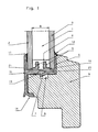
- An insulating element 1 consists essentially of two successive spaced apart Disks 2 and 3, which are connected to each other at their edge area by an adhesive 4.
- Such insulating elements are usually known as insulating glass panes, normally the air is sucked out between the panes 2 and 3 and thus a kind of vacuum is formed or else a corresponding gas is filled. For this reason there are 4 special glue Requirements are made, usually additional in the manufacture of such insulating elements spacer rails are still used. It is quite conceivable that such insulating elements are formed from more than two disks 2 and 3, the individual disks with a corresponding Spacing successively are connected to each other by the adhesive 4.
- a profile rail 20 is provided, this profile rail 20 or parts of this profile rail 20, namely webs 5, in the edge region between two panes 2, 3 intervention.
- the profile rails 20 or parts thereof are to be introduced over the edge area Adhesive 4 firmly connected to discs 2 and 3.
- the profile rail 20 is over the entire circumference of the panes arranged continuously, the profile rails in the corner areas, for example are mitered or butt against each other.
- the profile rail 20 is direct or indirectly connected to the panes 2, 3 of the insulating element 1 and thus forms one integrating part of the insulating element 1.
- the profile rail 20 is advantageously with a freely projecting Provide web 5, which then in the edge region between the panes 2 and 3 in the adhesive 4th is embedded.
- two are parallel to each other extending webs 5 available.
- Such a web or webs could then be T-shaped, for example.
- adhesives 4 are corresponding ribs, grooves or the like provided or the webs themselves are designed in the manner of a sawtooth-shaped profile.
- the adhesive 4 and the Causing discs 2 and 3 can be the most diverse here within the scope of the invention Profiling options are provided.
- the width B of the profile rail 20 corresponds to the distance B at least in a certain area between two successive panes 2, 3.
- the profile rail 20 can if necessary, replace the otherwise necessary spacer rail. If the profile rail 20 is not limited to a width B, at least corresponding stop surfaces 19, 21 are provided which determine the distance B between two successive disks 2, 3.
- the profile rail 20 has a tab 7 on the boundary facing away from the panes 2, 3. It can see several such tabs 7 provided on the length of the profile rail 20 here be, or there can be a continuous tab over the entire length of the profile rail be trained.
- the tab 7 can be pressed elastically against the profile rail 20 and advantageously formed in one piece with the profile rail 20.
- the tab 7 when inserting the Insulating element are pressed elastically against the profile rail 20. Is the insulating element 1 in the end position, the tab 7 snaps into a groove 8 formed on the frame 9.
- This enables the insulating element 1 to be installed in a frame 9 in a very simple and quick manner possible, regardless of whether the frame is a solid or hollow profile.
- the tab 7 and the corresponding Boundary on a frame 9 are equipped with ribs and / or depressions or grooves or have several grooves or roughenings in order to thereby already have a corresponding one To achieve force and / or positive locking. So there are a number of ways due to the special design of the profile rail 20, simple installation of an insulating element in to effect a frame, it does not matter whether it is a frame in a Window or door leaf or a fixed frame.
- the profile rail 20 overlaps the disks 2, 3 used on one or both sides. Accordingly, it is not just a question of an engagement between the disks 2, 3 Profile rail, but around a profile rail 20 in the manner of a real frame that is fixed and in is connected in one piece with the insulating element.
- the profile rail 20 according to FIG. 1 are on both sides in the direction of the disks 2, 3 protruding, on the outside Disc 2, 3 adjacent flanges 6 or profile parts 10 are formed.
- the profile part 10 are both corresponding sections towards the pane 2 and towards the frame 9 provided, with a conclusion at the bottom, for example, with a type of cover web 14.
- a type of water nose can also be formed, so that from the outside of the insulating element 1 running water does not drip down and not can flow in the direction of the frame 9.
- Sealant 11 or 12 are introduced or applied.
- the design according to FIG. 4 provides a similar construction to the design according to FIG. 1.
- the profile rail 20 includes one with an upward and one downward Section provided profile part 10.
- this profile part 10 only enters here corresponding sealing profile 15.
- the profile rail 20 is practically entirely in the edge area inserted between two disks 2, 3. It can be seen here that in such a profile rail 20th Fitting parts 18 or any fittings can be integrated directly. But it can also a very simple attachment option for the fittings or fitting parts 18 on the Profile rail 20 are created.
- FIG. 6 is practically a combination of the design 5 with an embodiment of the profile rail 20 according to FIGS. 1 to 4.
- a downwardly projecting area 16 is provided, the tab 7 when inserting the Insulating element 1 can snap into the frame 9 in a corresponding groove 8.
- the down projecting area 16 then covers this part of the frame 9 to the weather side.
- the measures according to the invention are in particular in door and window construction and in To use facade construction.
- an insulating element can also be used for partition walls be used.
- such insulating elements are formed from glass panes. But it is it is quite possible to provide washers made of plastic for such insulating elements.
- the Profile rails 20 are advantageously made of plastic, but also metal profile rails could be used.
Landscapes
- Engineering & Computer Science (AREA)
- Civil Engineering (AREA)
- Structural Engineering (AREA)
- Securing Of Glass Panes Or The Like (AREA)
- Connection Of Plates (AREA)
Abstract
Description
- Fig. 1
- einen Schnitt durch ein erfindungsgemäßes Isolierelement, welches in einen Holzrahmen eingesetzt ist;
- Fig. 2 bis Fig. 4
- verschiedene Ausführungsbeispiele von Isolierelementen mit verschieden gestalteten Profilschienen;
- Fig. 5
- einen Schnitt durch ein Isolierelement, bei welchem der eine Rand einer außen liegenden Scheibe gegenüber dem Rand der folgenden Scheibe vorsteht;
- Fig. 6
- ein Isolierelement mit ähnlicher Konstruktion wie in Fig. 5, wobei jedoch die Profilschiene anders gestaltet und das Isolierelement in einen Holzrahmen eingesetzt ist.
Claims (17)
- Isolierelement aus zwei oder mehreren, aus Glas oder Kunststoff gefertigten Scheiben (2, 3), bei dem die einzelnen, mit Abstand (B) aufeinander folgenden Scheiben (2, 3) zumindest an ihrem Randbereich unter Zwischenschaltung von Abstandhalteschienen oder dergleichen miteinander verklebt sind, wobei in den Randbereich zwischen zwei aufeinander folgenden Scheiben (2, 3) wenigstens eine Profilschiene (20) eingreift, dadurch gekennzeichnet, daß sich die Profilschiene (20) umfangsgeschlossen über den ganzen Scheibenumfang erstreckt und ganz oder teilweise über in den Randbereich zwischen Profilschiene (20) und Abstandhalteschienen eingebrachten Kleber (4) direkt oder indirekt mit den Scheiben (2, 3) verbunden ist.
- Isolierelement nach Anspruch 1, dadurch gekennzeichnet, daß die Profilschiene (20) wenigstens einen frei auskragenden Steg (5) aufweist, welcher in den im Randbereich zwischen zwei Scheiben (2, 3) aufgebrachten Kleber (4) eingebettet ist.
- Isolierelement nach Anspruch 2, dadurch gekennzeichnet, daß die Profilschiene (20) zwei oder mehr als zwei, im wesentlichen parallel zueinander verlaufende Stege (5) aufweist.
- Isolierelement nach Anspruch 2 oder 3, dadurch gekennzeichnet, daß die Stege (5) mit Rippen, Rillen oder dergleichen oder mit einem sägezahnförmigen Profil ausgeführt sind.
- Isolierelement nach einem der Ansprüche 1 bis 4, dadurch gekennzeichnet, daß die Breite (B) der Profilschiene (20) zumindest annähernd dem Abstand (B) zwischen zwei aufeinander folgenden Scheiben (2, 3) entspricht.
- Isolierelement nach einem der Ansprüche 1 bis 4, dadurch gekennzeichnet, daß an der Profilschiene (20) wenigstens zwei Anschlagflächen (19, 21) oder -nasen ausgebildet sind, welche den Abstand (B) zweier aufeinander folgender Scheiben (2, 3) bestimmen.
- Isolierelement nach einem der Ansprüche 1 bis 6, dadurch gekennzeichnet, daß die Profilschiene (20) an einer von den Scheiben (2, 3) abgewandten Begrenzung eine oder mehrere, elastisch gegen die Profilschiene (20) andrückbare Lasche(n) (7) aufweist.
- Isolierelement nach Anspruch 7, dadurch gekennzeichnet, daß die Lasche(n) (7) einstückig mit der Profilschiene (20) ausgebildet ist bzw. sind.
- Isolierelement nach Anspruch 7 oder 8, dadurch gekennzeichnet, daß eine über die ganze Länge der Profilschiene (20) durchgehende Lasche (7) vorgesehen ist.
- Isolierelement nach einem der Ansprüche 7 bis 9, dadurch gekennzeichnet, daß die Lasche(n) (7) in eine an einem als Voll- oder Hohlprofil ausgeführten Rahmen (9) ausgebildete Nut (8) oder in entsprechende Öffnungen an diesem Rahmen (9) einrastbar ist bzw. sind.
- Isolierelement nach einem der Ansprüche 7 bis 10, dadurch gekennzeichnet, daß in einen zwischen der (den) Lasche(n) (7) und der zugeordneten Oberfläche der Profilschiene (20) gebildeten Spalt (13) ein Steg (25) eines Verkleidungsprofils (22) kraft- und/oder formschlüssig einsteckbar ist.
- Isolierelement nach einem der Ansprüche 1 bis 11, dadurch gekennzeichnet, daß die Profilschiene (20) ein- oder beidseitig die eingesetzten Scheiben (2, 3) übergreift.
- Isolierelement nach einem der Ansprüche 1 bis 12, dadurch gekennzeichnet, daß die Profilschiene (20) ein- oder beidseitig einen in Richtung zu den Scheiben (2, 3) abstehenden, an der jeweils außen liegenden Scheibe (2, 3) anliegenden Flansch (6) aufweist.
- Isolierelement nach einem der Ansprüche 1 bis 13, dadurch gekennzeichnet, daß an wenigstens einem seitlichen Randbereich der Profilschiene (20) ein profilierter, mit Hinterschneidungen versehener Profilteil (24) anschließt zur form- und/oder kraftschlüssigen Aufnahme eines Verkleidungs- und/oder Dichtungsprofils (22, 23).
- Isolierelement nach einem der Ansprüche 1 bis 14, dadurch gekennzeichnet, daß die Profilschiene (20) zur Befestigung von Beschlagteilen (18) oder Beschlägen ausgebildet ist.
- Isolierelement nach einem der Ansprüche 1 bis 14, dadurch gekennzeichnet, daß in die Profilschiene (20) Beschlagteile (18) oder Beschläge integriert sind.
- Isolierelement nach einem der Ansprüche 1 bis 16, dadurch gekennzeichnet, daß die außen liegende Scheibe (2) des Isolierelementes (1) zumindest am unteren Randbereich desselben den Rand der anderen Scheiben (3) überragt, wobei dieser nach unten vorstehende Bereich (16) das Verkleidungsprofil bildet oder ersetzt.
Applications Claiming Priority (2)
| Application Number | Priority Date | Filing Date | Title |
|---|---|---|---|
| DE1997118714 DE19718714C2 (de) | 1997-05-02 | 1997-05-02 | Isolierelement aus zwei oder mehreren, aus Glas oder Kunststoff gefertigten Scheiben |
| DE19718714 | 1997-05-02 |
Publications (2)
| Publication Number | Publication Date |
|---|---|
| EP0875652A2 true EP0875652A2 (de) | 1998-11-04 |
| EP0875652A3 EP0875652A3 (de) | 1999-11-24 |
Family
ID=7828525
Family Applications (2)
| Application Number | Title | Priority Date | Filing Date |
|---|---|---|---|
| EP98106769A Withdrawn EP0875652A3 (de) | 1997-05-02 | 1998-04-14 | Isolierelement aus zwei oder mehreren, aus Glas oder Kunststoff gefertigten Scheiben |
| EP98107698A Withdrawn EP0875653A3 (de) | 1997-05-02 | 1998-04-28 | Isolierelement aus wenigstens zwei Glas- oder Kunststoffscheiben und mit Profilschienen oder -teilen zur Montage in einem Rahmen |
Family Applications After (1)
| Application Number | Title | Priority Date | Filing Date |
|---|---|---|---|
| EP98107698A Withdrawn EP0875653A3 (de) | 1997-05-02 | 1998-04-28 | Isolierelement aus wenigstens zwei Glas- oder Kunststoffscheiben und mit Profilschienen oder -teilen zur Montage in einem Rahmen |
Country Status (2)
| Country | Link |
|---|---|
| EP (2) | EP0875652A3 (de) |
| DE (1) | DE19758464C2 (de) |
Cited By (3)
| Publication number | Priority date | Publication date | Assignee | Title |
|---|---|---|---|---|
| GB2405418A (en) * | 2003-08-28 | 2005-03-02 | Martec Engineering Group Ltd | Panelling system |
| GB2407827B (en) * | 2003-10-29 | 2007-07-25 | Komfort Office Environments | Tensioned locking device |
| US8523291B2 (en) | 2010-03-19 | 2013-09-03 | Caterpillar Inc. | Compactor wheel tip |
Families Citing this family (5)
| Publication number | Priority date | Publication date | Assignee | Title |
|---|---|---|---|---|
| DE19931171A1 (de) * | 1999-07-06 | 2001-01-11 | Peter Willrich | Fenstersystem mit einer Fensterscheibe, die mindestens zwei Glasscheiben und eine Beschlagnut aufweist |
| NL1022030C2 (nl) * | 2002-11-29 | 2004-06-11 | Doorwin B V | Ruit/kozijnsamenstel voorzien van opsluitmiddelen. |
| DE202005012108U1 (de) * | 2005-08-02 | 2005-11-24 | Clad Engineering | Verglasungssystem |
| FR2971285B1 (fr) * | 2011-02-03 | 2015-09-18 | Didier Fraysse | Garniture d'etancheite sous vitrage et entre le dormant et l'ouvrant pour fenetre aluminium, pvc, et bois |
| CN105064865B (zh) * | 2015-08-17 | 2017-03-01 | 惠安县泰达商贸有限责任公司 | 一种简易室内翻转式窗体结构 |
Citations (4)
| Publication number | Priority date | Publication date | Assignee | Title |
|---|---|---|---|---|
| DE3408161A1 (de) | 1984-03-06 | 1985-09-12 | Franz Mayer'sche Hofkunstanstalt und Glasmalerei, 8000 München | Schutzverglasung fuer bleiversprosste glasscheiben |
| DE8800333U1 (de) | 1988-01-14 | 1988-03-10 | VEGLA Vereinigte Glaswerke GmbH, 5100 Aachen | Isolierglasscheibe mit einer Bohrung zur Befestigung eines Beschlagteils |
| DE29507176U1 (de) | 1995-04-28 | 1995-08-03 | Dorma Gmbh + Co. Kg, 58256 Ennepetal | Rahmenlose Glastür |
| DE19547444A1 (de) | 1994-12-22 | 1996-06-27 | Glaverbel | Mehrfachverglasungseinheit und Verfahren zu deren Herstellung |
Family Cites Families (9)
| Publication number | Priority date | Publication date | Assignee | Title |
|---|---|---|---|---|
| FR2301675A1 (fr) * | 1975-02-19 | 1976-09-17 | Pasquali Jean | Menuiserie metall |
| DE8301436U1 (de) * | 1983-01-20 | 1988-09-15 | Messerschmitt-Boelkow-Blohm Gmbh, 8012 Ottobrunn, De | |
| DE3343566A1 (de) * | 1983-12-01 | 1985-06-13 | Glaszentrum Denzel GmbH, 8000 München | Kantenschutz fuer isolierglasscheiben |
| DE8534250U1 (de) * | 1985-12-05 | 1986-03-06 | Herotherm Isolierglas GmbH, 2991 Dersum | Isolierglaselement aus Einzelfeldern |
| DE3543524A1 (de) * | 1985-12-10 | 1987-06-25 | Eltreva Ag | Fenster- oder tuerfluegel |
| DE3702402C2 (de) * | 1987-01-28 | 1995-10-12 | Ver Glaswerke Gmbh | Höhenverstellbare Seitenscheibe aus Isolierglas für Kraftfahrzeuge und Verfahren zu ihrer Herstellung |
| SE469800B (sv) * | 1989-01-20 | 1993-09-13 | Termofrost Sweden Ab | Dörrbladsprofil |
| US5228240A (en) * | 1992-01-28 | 1993-07-20 | 2420 Door Co. | Refrigerator door assembly and method |
| DE4407892A1 (de) * | 1994-03-10 | 1995-09-14 | Mecalit Gmbh | Glas-Verbundscheibe und Verfahren zu ihrer Herstellung |
-
1997
- 1997-05-02 DE DE19758464A patent/DE19758464C2/de not_active Expired - Fee Related
-
1998
- 1998-04-14 EP EP98106769A patent/EP0875652A3/de not_active Withdrawn
- 1998-04-28 EP EP98107698A patent/EP0875653A3/de not_active Withdrawn
Patent Citations (4)
| Publication number | Priority date | Publication date | Assignee | Title |
|---|---|---|---|---|
| DE3408161A1 (de) | 1984-03-06 | 1985-09-12 | Franz Mayer'sche Hofkunstanstalt und Glasmalerei, 8000 München | Schutzverglasung fuer bleiversprosste glasscheiben |
| DE8800333U1 (de) | 1988-01-14 | 1988-03-10 | VEGLA Vereinigte Glaswerke GmbH, 5100 Aachen | Isolierglasscheibe mit einer Bohrung zur Befestigung eines Beschlagteils |
| DE19547444A1 (de) | 1994-12-22 | 1996-06-27 | Glaverbel | Mehrfachverglasungseinheit und Verfahren zu deren Herstellung |
| DE29507176U1 (de) | 1995-04-28 | 1995-08-03 | Dorma Gmbh + Co. Kg, 58256 Ennepetal | Rahmenlose Glastür |
Cited By (4)
| Publication number | Priority date | Publication date | Assignee | Title |
|---|---|---|---|---|
| GB2405418A (en) * | 2003-08-28 | 2005-03-02 | Martec Engineering Group Ltd | Panelling system |
| GB2405418B (en) * | 2003-08-28 | 2008-02-13 | Martec Engineering Group Ltd | Panelling system |
| GB2407827B (en) * | 2003-10-29 | 2007-07-25 | Komfort Office Environments | Tensioned locking device |
| US8523291B2 (en) | 2010-03-19 | 2013-09-03 | Caterpillar Inc. | Compactor wheel tip |
Also Published As
| Publication number | Publication date |
|---|---|
| DE19758464A1 (de) | 1998-11-12 |
| EP0875653A2 (de) | 1998-11-04 |
| EP0875653A3 (de) | 1999-11-24 |
| DE19758464C2 (de) | 2001-09-20 |
| EP0875652A3 (de) | 1999-11-24 |
Similar Documents
| Publication | Publication Date | Title |
|---|---|---|
| WO1993002268A1 (de) | Feuerwiderstandsfähige glastrennwand | |
| DE4007247A1 (de) | Trocken-druck-verglasungsanordnung fuer fassaden- und dach-konstruktionen in pfosten-riegel-bauweise | |
| EP1020579B1 (de) | Fassade oder Lichtdach mit einer Dichtung | |
| DE19718714C2 (de) | Isolierelement aus zwei oder mehreren, aus Glas oder Kunststoff gefertigten Scheiben | |
| EP2666948A1 (de) | Rahmenanordnung für ein Sektionaltorpaneel | |
| WO1994025716A1 (de) | Verbundprofil | |
| EP0225473A1 (de) | Fenster- oder Türflügel | |
| DE69026501T2 (de) | Fenster, tür oder ähnliche abschlüsse | |
| DE19758464C2 (de) | Isolierelement aus wenigstens zwei Glas- oder Kunststoffscheiben und mit Profilschienen oder -teilen zur Montage in einem Rahmen | |
| DE19516464A1 (de) | Bausatz zur Halterung einer aus Platten, insbesondere Glasplatten oder dergleichen zusammensetzbaren Fassade oder Dacheindeckung | |
| EP3677746B1 (de) | Profileinheit zur rollladenführung und befestigung wenigstens eines absturzsicherungselements an einem blendrahmen oder pfosten eines fensters | |
| EP1510644A2 (de) | Fenster- oder Türkonstruktion | |
| EP3543450B1 (de) | Hebeschiebetür-/schiebetür-profilsystem | |
| EP0524631B1 (de) | Halteglied für Isolierglasscheiben | |
| DE19859166C2 (de) | Verbundprofil für Fenster oder Türen | |
| DE3616408C1 (de) | Verglasung fuer Gewaechshaeuser oder dergleichen sowie dabei verwendbare Glasscheibe | |
| DE2235858A1 (de) | Verbindungseinrichtung fuer aus profilstaeben und einer isolierglasscheibe bestehende fluegel fuer fenster, tueren od. dgl | |
| EP0477544B1 (de) | Füllstück für Halteleisten von Glasscheiben in Toren | |
| DE20100617U1 (de) | Rahmenprofilanordnung | |
| EP0448808A2 (de) | Fenster, Tür o. dgl. für Gebäude mit einer Verglasung | |
| DE4324656C2 (de) | Glasrandhalterung | |
| DE10321685B4 (de) | Tür-oder Fensterflügel mit einer Isolierverglasung | |
| DE3528388A1 (de) | Elastische profildichtung fuer isolierverglasungen | |
| DE2607779A1 (de) | Verfahren zum einsetzen von vorgefertigten metallblendrahmen in vorhandene holzblendrahmen und vorrichtung zur durchfuehrung dieses verfahrens | |
| EP0869252A2 (de) | Anordnung zur kraft- und/oder formschlüssigen Halterung von Profilleisten an einem Fenster- oder einem Türrahmen bzw. -flügel |
Legal Events
| Date | Code | Title | Description |
|---|---|---|---|
| PUAI | Public reference made under article 153(3) epc to a published international application that has entered the european phase |
Free format text: ORIGINAL CODE: 0009012 |
|
| AK | Designated contracting states |
Kind code of ref document: A2 Designated state(s): AT BE CH DE DK ES FR IT LI NL |
|
| AX | Request for extension of the european patent |
Free format text: AL;LT;LV;MK;RO;SI PAYMENT 980414 |
|
| PUAL | Search report despatched |
Free format text: ORIGINAL CODE: 0009013 |
|
| AK | Designated contracting states |
Kind code of ref document: A3 Designated state(s): AT BE CH DE DK ES FI FR GB GR IE IT LI LU MC NL PT SE |
|
| AX | Request for extension of the european patent |
Free format text: AL;LT;LV;MK;RO;SI PAYMENT 19980414 |
|
| RAP1 | Party data changed (applicant data changed or rights of an application transferred) |
Owner name: SFS HANDELS HOLDING AG |
|
| 17P | Request for examination filed |
Effective date: 20000508 |
|
| AKX | Designation fees paid |
Free format text: AT BE CH DE DK ES FR IT LI NL |
|
| AXX | Extension fees paid |
Free format text: SI PAYMENT 19980414 |
|
| 17Q | First examination report despatched |
Effective date: 20030402 |
|
| STAA | Information on the status of an ep patent application or granted ep patent |
Free format text: STATUS: THE APPLICATION IS DEEMED TO BE WITHDRAWN |
|
| 18D | Application deemed to be withdrawn |
Effective date: 20031014 |