EP0875675A2 - Système de suralimentation de moteur avec suralimenteur du type à vis - Google Patents
Système de suralimentation de moteur avec suralimenteur du type à vis Download PDFInfo
- Publication number
- EP0875675A2 EP0875675A2 EP98107057A EP98107057A EP0875675A2 EP 0875675 A2 EP0875675 A2 EP 0875675A2 EP 98107057 A EP98107057 A EP 98107057A EP 98107057 A EP98107057 A EP 98107057A EP 0875675 A2 EP0875675 A2 EP 0875675A2
- Authority
- EP
- European Patent Office
- Prior art keywords
- water
- supercharger
- intake air
- engine
- supercharging system
- Prior art date
- Legal status (The legal status is an assumption and is not a legal conclusion. Google has not performed a legal analysis and makes no representation as to the accuracy of the status listed.)
- Withdrawn
Links
Images
Classifications
-
- F—MECHANICAL ENGINEERING; LIGHTING; HEATING; WEAPONS; BLASTING
- F04—POSITIVE - DISPLACEMENT MACHINES FOR LIQUIDS; PUMPS FOR LIQUIDS OR ELASTIC FLUIDS
- F04B—POSITIVE-DISPLACEMENT MACHINES FOR LIQUIDS; PUMPS
- F04B37/00—Pumps having pertinent characteristics not provided for in, or of interest apart from, groups F04B25/00 - F04B35/00
- F04B37/10—Pumps having pertinent characteristics not provided for in, or of interest apart from, groups F04B25/00 - F04B35/00 for special use
- F04B37/18—Pumps having pertinent characteristics not provided for in, or of interest apart from, groups F04B25/00 - F04B35/00 for special use for specific elastic fluids
- F04B37/20—Pumps having pertinent characteristics not provided for in, or of interest apart from, groups F04B25/00 - F04B35/00 for special use for specific elastic fluids for wet gases, e.g. wet air
-
- F—MECHANICAL ENGINEERING; LIGHTING; HEATING; WEAPONS; BLASTING
- F02—COMBUSTION ENGINES; HOT-GAS OR COMBUSTION-PRODUCT ENGINE PLANTS
- F02B—INTERNAL-COMBUSTION PISTON ENGINES; COMBUSTION ENGINES IN GENERAL
- F02B33/00—Engines characterised by provision of pumps for charging or scavenging
- F02B33/32—Engines with pumps other than of reciprocating-piston type
- F02B33/34—Engines with pumps other than of reciprocating-piston type with rotary pumps
- F02B33/36—Engines with pumps other than of reciprocating-piston type with rotary pumps of positive-displacement type
-
- F—MECHANICAL ENGINEERING; LIGHTING; HEATING; WEAPONS; BLASTING
- F02—COMBUSTION ENGINES; HOT-GAS OR COMBUSTION-PRODUCT ENGINE PLANTS
- F02M—SUPPLYING COMBUSTION ENGINES IN GENERAL WITH COMBUSTIBLE MIXTURES OR CONSTITUENTS THEREOF
- F02M25/00—Engine-pertinent apparatus for adding non-fuel substances or small quantities of secondary fuel to combustion-air, main fuel or fuel-air mixture
- F02M25/022—Adding fuel and water emulsion, water or steam
- F02M25/0227—Control aspects; Arrangement of sensors; Diagnostics; Actuators
-
- F—MECHANICAL ENGINEERING; LIGHTING; HEATING; WEAPONS; BLASTING
- F02—COMBUSTION ENGINES; HOT-GAS OR COMBUSTION-PRODUCT ENGINE PLANTS
- F02M—SUPPLYING COMBUSTION ENGINES IN GENERAL WITH COMBUSTIBLE MIXTURES OR CONSTITUENTS THEREOF
- F02M25/00—Engine-pertinent apparatus for adding non-fuel substances or small quantities of secondary fuel to combustion-air, main fuel or fuel-air mixture
- F02M25/022—Adding fuel and water emulsion, water or steam
- F02M25/025—Adding water
- F02M25/028—Adding water into the charge intakes
-
- Y—GENERAL TAGGING OF NEW TECHNOLOGICAL DEVELOPMENTS; GENERAL TAGGING OF CROSS-SECTIONAL TECHNOLOGIES SPANNING OVER SEVERAL SECTIONS OF THE IPC; TECHNICAL SUBJECTS COVERED BY FORMER USPC CROSS-REFERENCE ART COLLECTIONS [XRACs] AND DIGESTS
- Y02—TECHNOLOGIES OR APPLICATIONS FOR MITIGATION OR ADAPTATION AGAINST CLIMATE CHANGE
- Y02T—CLIMATE CHANGE MITIGATION TECHNOLOGIES RELATED TO TRANSPORTATION
- Y02T10/00—Road transport of goods or passengers
- Y02T10/10—Internal combustion engine [ICE] based vehicles
- Y02T10/12—Improving ICE efficiencies
Definitions
- the present invention generally relates to a supercharging system equipped with a supercharger connected to an engine of an automobile for supercharging an intake air, and more particularly to such a supercharging system employing a screw supercharger which can improve a fuel consumption rate of the engine and eliminate knocking of the engine.
- the screw supercharger generally includes a male screw rotor and a female screw rotor engaged with each other, and these rotors are rotated by an engine to compress an intake air to be supplied to the engine.
- An ordinary gasoline engine provided with a screw supercharge has a carburetor up stream of the supercharger, and the carburetor feeds a mixture of gasoline and air to the screw supercharger.
- the gasoline reduces leakage of the compressed air and cools the compressed air.
- recent demands for a lower fuel consumption rate, higher output and less exhaust gas require that fuel injection takes place immediately upstream of or inside the engine. In other words, the fuel injection upstream of the supercharger is impossible.
- One object of the present invention is to propose a supercharging system for an automobile engine equipped with a screw supercharger which can reduce leakage of the compressed air from a body of the supercharger, which can improve a fuel consumption rate of the engine and which can suppress knocking of the engine.
- a supercharging system for a vehicle engine comprising a screw supercharger connected to an intake air pipe, and a water feed mechanism connected to the intake air pipe upstream of the supercharger.
- An intake air flows in the engine after compressed by the screw supercharger.
- Fuel is injected inside the engine or immediately before the engine or downstream of the supercharger.
- water is mixed with the intake air as fed from the water feed mechanism.
- a water-air mixture enters the supercharger and compressed therein.
- the water contained in the intake air reduces leakage of the compressed air from a body of the supercharger.
- the water also lowers the intake air temperature so that a volumetric efficiency is improved (i.e., larger amount of air can be introduced to the engine) and therefore an engine output is raised.
- the water feeding is also effective in knocking prevention.
- the water feed mechanism may include a water tank and a duty solenoid valve located between the water tank and intake air pipe.
- An amount of water to be mixed with the intake air is controlled by the duty solenoid valve according to various parameters such as a rotational speed of the supercharger and inclination of an accelerator pedal pedaled by a foot of a driver of a vehicle.
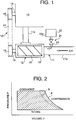
- an engine 10 of an automobile or the like has an intake air pipe 11 and a screw supercharger 12 connected to the intake air pipe 11.
- the screw supercharger 12 compresses an intake air and compressed air is supplied to the engine 10.
- Fuel is injected inside the engine or just upstream of the engine or downstream of the supercharger 12.
- a shaft 13 of the screw supercharger 12 is connected to a crankshaft 14 of the engine 10 by a connection mechanism 18 including pulleys 15 and 16 and a belt 17.
- the screw supercharger 12 has a casing 19 and a couple of male and female screw rotors 20 engaged with each other.
- the screw rotors 20 rotate in the casing 19 to compress an intake air entering from an upstream pipe segment 11a of the intake air pipe 11, and it discharges a compressed air to a downstream pipe segment 11b.
- a water feed mechanism 21 is connected to the upstream pipe segment 11a to mix the intake air with water so as to prevent compressed air leakage from the supercharger 12 and to cool the compressed air.
- the water feed mechanism 21 includes a water tank 22 and a duty solenoid valve 23 which can arbitrarily adjust or determine an amount of water to be mixed with the intake air.
- a water surface sensor 22a is attached to the water tank 22 for detecting a remaining amount of water in the water tank 22.
- a detection signal is sent to a suitable indicator (not shown) from the sensor 22a.
- the duty solenoid valve 23 can change a flow rate in proportion to its duty ratio. It is possible to change the duty ratio between 0% and 100%.
- the duty ratio of the duty solenoid valve 23 is adjusted by a controller (not shown) according to a load condition (or running condition) of the engine 10 so as to adjust an amount of water to be fed to the intake air to an appropriate value.
- This controller is a controller which is originally provided for controlling the engine 10.
- the screw supercharger 12 is driven by the power transmission mechanism 18 such that an intake air flowing from the upstream air pipe 11a is compressed by the supercharger 12 and fed to the engine 10 from the supercharger 10 through the downstream air pipe 11b.
- the water supplied to the upstream air pipe 11a and mixed with the intake air reduces the compressed air leakage and cools the compressed air.
- the compressed air is cooled by, for example, vaporization latent heat of the water. Because of this, volume efficiency and temperature efficiency are both improved, a work needed to drive the supercharger is reduced, and an outlet temperature of the super charger is lowered. Accordingly, the fuel consumption of the engine 10 is improved and knocking is suppressed. Experiments revealed that knocking is suppressed as the air temperature (at a supercharger exit) drops.
- FIG. 2 illustrates P-V (pressure-volume) diagram to show a work of the screw supercharger 12.
- the screw supercharger 12 undergoes an intake process, compression process and discharge process, and returns to the intake process.
- the work done by the screw supercharger 12 is indicated by the oblique lines.
- the compression curve of the conventional supercharging system which has no water feeding mechanism is indicated by the solid line a.
- the compression curve of the supercharging system according to the present invention is indicated the chain line b.
- its compression rate or compressibility of the present invention is better than the conventional arrangement.
- the compression curve is shifted to the left in Figure 2 (from “a” to "b") . This means that an amount of work between the lines a and b is dispensed with by the invention.
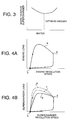
- Figure 3 illustrates relationship between an amount of water to be fed to the supercharger 12 from the water tank 22 and a work needed to drive the supercharger 12 (i .e., work of the supercharger 12).
- the work needed to drive the supercharger 12 is determined according to a revolution speed of the rotors 20 and an air flow rate at an exit of the supercharger housing 19.
- the supercharger 12 is driven under a particular running condition whereas the amount of water is varied to acquire the work-water curve of Figure 3. If a larger work is necessary to drive the supercharger to obtain a predetermined output, it means that there is larger air leakage. If a less work is needed, it means that air leakage is smaller or reduced.
- Figure 4A shows relationship between an engine rotational speed and an engine load when the vehicle runs according to the above mentioned manner.
- the black dot "c” indicates the idling condition
- the white dot “d” indicates the constant speed driving
- the curve “e” indicates the engine load.
- the supercharger load when the engine is operated in the above mentioned manner is illustrated in Figure 4B.
- the supercharger load is basically determined by the air flow rate at the exit of the supercharger 12.
- the curve “f” indicates a case of no water feeding
- the curve “g” indicates a case of optimum water feeding
- the curve “h” indicates a case of excessive water feeding.
- the point “c” represents the idling and the point “d” represents the constant speed driving, which is the same as Figure 4A.
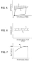
- Figure 5 illustrates a duty ratio of the duty solenoid valve 23 relative to the revolution speed of the supercharger 12.
- the amount of water to be mixed with the intake air is controlled by the duty ratio of the solenoid valve 23 since the solenoid valve 23 of the water feed mechanism 21 determines how much water is allowed to flow into the intake air pipe 11a.
- the curve "i" in Figure 5 is drawn according to the curve "g" of Figure 4B and the optimum water range (vertical broken line) of Figure 3 and it indicates the optimum duty ratio curve.
- the minimum supercharger load relative to the supercharger rotational speed is determined from Figure 4B and the optimum water range is determined from Figure 3 so that the optimum water supplement relative to the supercharger rotational speed can be determined from Figures 4B and 3.
- the optimum water supplement is expressed in terms of duty ratio of the duty solenoid valve 23 and the control curve "i" is drawn. If a simple on-off valve is employed instead of the duty solenoid valve, there is a tendency that an excessive amount of water be supplied, and an adverse effect may result (shaded area "j" above the curve "i").
- Control parameters to the duty ratio of the duty solenoid valve 23 includes a rotational speed of the supercharger 12 (or rotational speed of the engine 10), an air flow rate at the exit of the supercharger 12, an opening degree of an accelerator in a carburetor (or degree of inclination of an accelerator pedal pedaled by a driver's foot), a gear position (or shift position) of an engine transmission (e.g., "low", “2nd", “3rd” and “drive”) and an air temperature.
- the water feeding according to the present invention is particularly advantageous when the air temperature is high.
- knocking prevention will be described.
- the engine output is improved or raised if the knocking is prevented.
- the engine does not demonstrate its maximum output in an actual driving.
- An actual upper limit of the engine output is lower than a theoretical value due to knocking if the engine is a gasoline engine equipped with a supercharger.
- Figure 6 illustrates the engine load relative to the engine revolution speed.
- the curve “k” indicates a limitation curve for knocking when no water is fed and the curve “l” indicates a knocking limitation when water is fed in the optimum manner.
- the "limitation for knocking” is a maximum engine load without causing knocking at a particular engine rotational speed. An optimum amount of water is mixed with the intake air using the duty solenoid valve 23 in this embodiment.
- the knocking limitation curve is shifted upward (from “k” to “l” ), and the engine output is correspondingly raised.
- the supercharger exit temperature is lowered by the water mixed with the intake air.
- the intake air temperature is lowered by the water fed from the water tank 22.
- the lower the intake air temperature the more the intake air is fed to the engine.
- the engine output is improved if a larger amount of air is introduced to the engine. In particular, this is advantageous if the engine is not equipped with an intercooler.
- Figure 7 illustrates a duty ratio relative to the supercharger revolution speed when the engine is operated in the maximum load condition as shown in Figure 6.
- This characteristic curve "m" is drawn by employing a duty solenoid valve of which duty ratio becomes 100% and the amount of water to be fed from the water tank 22 is optimum when the revolution speed of the supercharger 12 is maximum.
- the optimum duty ratio is determined by the revolution speed, the air flow rate, an opening degree of an accelerator, data obtained from a knocking sensor (including a kind of gasoline), an external air temperature, a temperature of a water flowing in the engine 10 and the like.
- the air temperature and water temperature are concerned because time and season as well as location and area would affect the optimum duty ratio.
- the duty solenoid valve may be replaced with a valve controlled by a stepping motor.
- a water temperature of the water in the water tank may be detected and may be used another parameter in controlling the duty ratio of the solenoid valve.
- a water temperature sensor (not shown) may be provided in the water tank 22.
Landscapes
- Engineering & Computer Science (AREA)
- Mechanical Engineering (AREA)
- General Engineering & Computer Science (AREA)
- Chemical & Material Sciences (AREA)
- Combustion & Propulsion (AREA)
- Supercharger (AREA)
Applications Claiming Priority (3)
| Application Number | Priority Date | Filing Date | Title |
|---|---|---|---|
| JP9112951A JPH10299498A (ja) | 1997-04-30 | 1997-04-30 | スクリュ形過給機を用いたエンジン過給システム |
| JP11295197 | 1997-04-30 | ||
| JP112951/97 | 1997-04-30 |
Publications (2)
| Publication Number | Publication Date |
|---|---|
| EP0875675A2 true EP0875675A2 (fr) | 1998-11-04 |
| EP0875675A3 EP0875675A3 (fr) | 1999-06-16 |
Family
ID=14599619
Family Applications (1)
| Application Number | Title | Priority Date | Filing Date |
|---|---|---|---|
| EP98107057A Withdrawn EP0875675A3 (fr) | 1997-04-30 | 1998-04-17 | Système de suralimentation de moteur avec suralimenteur du type à vis |
Country Status (2)
| Country | Link |
|---|---|
| EP (1) | EP0875675A3 (fr) |
| JP (1) | JPH10299498A (fr) |
Families Citing this family (1)
| Publication number | Priority date | Publication date | Assignee | Title |
|---|---|---|---|---|
| JP6560317B2 (ja) * | 2017-10-27 | 2019-08-14 | 本田技研工業株式会社 | 内燃機関の水噴射装置の取付構造 |
Family Cites Families (9)
| Publication number | Priority date | Publication date | Assignee | Title |
|---|---|---|---|---|
| FR2050848A5 (fr) * | 1969-06-26 | 1971-04-02 | Saviem | |
| US4541383A (en) * | 1981-02-17 | 1985-09-17 | Chevron Research Company | Method and apparatus for minimum knock operation of an internal combustion engine on low knock-rated fuel |
| DE3142851A1 (de) * | 1981-10-29 | 1983-06-01 | Gerhard 8034 Germering Schumann | "zusatzstoffregelung fuer verbrennungskraftmaschinen" |
| IT1155952B (it) * | 1982-09-28 | 1987-01-28 | Fiat Auto Spa | Sistema di alimentazione per motori diesel sovralimentati |
| JPS6035117A (ja) * | 1983-08-05 | 1985-02-22 | Toyota Motor Corp | 内燃機関用過給装置の運転制御方法 |
| US4630642A (en) * | 1984-12-03 | 1986-12-23 | Tom Mcguane Industries, Inc. | Check valve and water injection systems and fuel systems utilizing the same |
| US4993386A (en) * | 1988-12-29 | 1991-02-19 | Kabushiki Kaisha Toyota Chuo Kenkyusho | Operation control system for internal combustion engine |
| SE468324B (sv) * | 1991-01-21 | 1992-12-14 | Edstroem Consulting Ab | Anordning vid en ottomotor foer framdrivning av ett fordon |
| JPH07189715A (ja) * | 1993-12-27 | 1995-07-28 | Mitsubishi Motors Corp | エンジンの過給システム |
-
1997
- 1997-04-30 JP JP9112951A patent/JPH10299498A/ja active Pending
-
1998
- 1998-04-17 EP EP98107057A patent/EP0875675A3/fr not_active Withdrawn
Also Published As
| Publication number | Publication date |
|---|---|
| JPH10299498A (ja) | 1998-11-10 |
| EP0875675A3 (fr) | 1999-06-16 |
Similar Documents
| Publication | Publication Date | Title |
|---|---|---|
| US5117799A (en) | Control system for a supercharged internal combustion engine | |
| EP1757788B1 (fr) | Moteur à variation de rapport de compression, de rapport air/carburant et d'état de surcompression | |
| EP1460247B1 (fr) | Dispositif et procédé de controle d'un moteur à combustion interne | |
| US6029452A (en) | Charge air systems for four-cycle internal combustion engines | |
| US6182449B1 (en) | Charge air systems for two-cycle internal combustion engines | |
| US4505117A (en) | Turbocharged internal combustion engine having an engine driven positive displacement compressor | |
| US4498429A (en) | Fuel intake system for supercharged engine | |
| JPH11218031A (ja) | ターボチャージャ作動制御のために学習ウエストゲート制御信号を用いる装置及びその方法 | |
| US6141965A (en) | Charge air systems for four-cycle internal combustion engines | |
| EP0878614B1 (fr) | Suralimenteur à vis pour véhicule | |
| US5724936A (en) | Engine component layout for outboard motor | |
| EP0875675A2 (fr) | Système de suralimentation de moteur avec suralimenteur du type à vis | |
| EP0807751A2 (fr) | Appareil de contrÔle du ralenti d'un moteur à combustion interne | |
| WO2000032917A1 (fr) | Moteur thermique suralimente avec compresseur electrique | |
| US4467608A (en) | Control method and apparatus for an internal combustion engine with a turbocharger | |
| EP0787896A2 (fr) | Dispositif de commande de la quantité d'air admise dans l'admission d'un moteur à combustion interne | |
| WO1995008704A1 (fr) | Moteur a combustion interne suralimente | |
| KR200310864Y1 (ko) | 모터구동형 슈퍼차져 | |
| KR100218893B1 (ko) | 대형 차량의 구동력 증강을 위한 흡기장치 | |
| GB2365065A (en) | Supercharging i.c. engines | |
| SE468324B (sv) | Anordning vid en ottomotor foer framdrivning av ett fordon | |
| US10731548B2 (en) | Mechanical supercharging system | |
| JPH05125947A (ja) | 内燃機関の吸気制御装置 | |
| JPS61149521A (ja) | 過給機付内燃機関 | |
| JPS6036757Y2 (ja) | 過給エンジン |
Legal Events
| Date | Code | Title | Description |
|---|---|---|---|
| PUAI | Public reference made under article 153(3) epc to a published international application that has entered the european phase |
Free format text: ORIGINAL CODE: 0009012 |
|
| AK | Designated contracting states |
Kind code of ref document: A2 Designated state(s): DE FR GB |
|
| AX | Request for extension of the european patent |
Free format text: AL;LT;LV;MK;RO;SI |
|
| PUAL | Search report despatched |
Free format text: ORIGINAL CODE: 0009013 |
|
| AK | Designated contracting states |
Kind code of ref document: A3 Designated state(s): AT BE CH CY DE DK ES FI FR GB GR IE IT LI LU MC NL PT SE |
|
| AX | Request for extension of the european patent |
Free format text: AL;LT;LV;MK;RO;SI |
|
| 17P | Request for examination filed |
Effective date: 19991126 |
|
| AKX | Designation fees paid |
Free format text: DE FR GB |
|
| 17Q | First examination report despatched |
Effective date: 20020129 |
|
| STAA | Information on the status of an ep patent application or granted ep patent |
Free format text: STATUS: THE APPLICATION HAS BEEN WITHDRAWN |
|
| 18W | Application withdrawn |
Withdrawal date: 20020306 |