EP0875683A1 - Wälzlager mit Messwertgeber - Google Patents
Wälzlager mit Messwertgeber Download PDFInfo
- Publication number
- EP0875683A1 EP0875683A1 EP98401008A EP98401008A EP0875683A1 EP 0875683 A1 EP0875683 A1 EP 0875683A1 EP 98401008 A EP98401008 A EP 98401008A EP 98401008 A EP98401008 A EP 98401008A EP 0875683 A1 EP0875683 A1 EP 0875683A1
- Authority
- EP
- European Patent Office
- Prior art keywords
- sensor
- rolling bearing
- support
- ring
- housing
- Prior art date
- Legal status (The legal status is an assumption and is not a legal conclusion. Google has not performed a legal analysis and makes no representation as to the accuracy of the status listed.)
- Granted
Links
- 238000005096 rolling process Methods 0.000 title claims description 39
- 238000001514 detection method Methods 0.000 claims description 7
- 230000000295 complement effect Effects 0.000 claims description 2
- 230000003287 optical effect Effects 0.000 claims description 2
- 238000005553 drilling Methods 0.000 claims 1
- 230000005405 multipole Effects 0.000 claims 1
- 230000000717 retained effect Effects 0.000 abstract 1
- 239000006185 dispersion Substances 0.000 description 2
- 238000006073 displacement reaction Methods 0.000 description 2
- 239000002184 metal Substances 0.000 description 2
- 229920002994 synthetic fiber Polymers 0.000 description 2
- 238000010276 construction Methods 0.000 description 1
- 230000000694 effects Effects 0.000 description 1
- 239000006249 magnetic particle Substances 0.000 description 1
- 238000004519 manufacturing process Methods 0.000 description 1
- 239000000463 material Substances 0.000 description 1
- 210000000056 organ Anatomy 0.000 description 1
- 239000011347 resin Substances 0.000 description 1
- 229920005989 resin Polymers 0.000 description 1
- 238000003466 welding Methods 0.000 description 1
Images



Classifications
-
- F—MECHANICAL ENGINEERING; LIGHTING; HEATING; WEAPONS; BLASTING
- F16—ENGINEERING ELEMENTS AND UNITS; GENERAL MEASURES FOR PRODUCING AND MAINTAINING EFFECTIVE FUNCTIONING OF MACHINES OR INSTALLATIONS; THERMAL INSULATION IN GENERAL
- F16C—SHAFTS; FLEXIBLE SHAFTS; ELEMENTS OR CRANKSHAFT MECHANISMS; ROTARY BODIES OTHER THAN GEARING ELEMENTS; BEARINGS
- F16C41/00—Other accessories, e.g. devices integrated in the bearing not relating to the bearing function as such
- F16C41/007—Encoders, e.g. parts with a plurality of alternating magnetic poles
-
- F—MECHANICAL ENGINEERING; LIGHTING; HEATING; WEAPONS; BLASTING
- F16—ENGINEERING ELEMENTS AND UNITS; GENERAL MEASURES FOR PRODUCING AND MAINTAINING EFFECTIVE FUNCTIONING OF MACHINES OR INSTALLATIONS; THERMAL INSULATION IN GENERAL
- F16C—SHAFTS; FLEXIBLE SHAFTS; ELEMENTS OR CRANKSHAFT MECHANISMS; ROTARY BODIES OTHER THAN GEARING ELEMENTS; BEARINGS
- F16C33/00—Parts of bearings; Special methods for making bearings or parts thereof
- F16C33/30—Parts of ball or roller bearings
- F16C33/58—Raceways; Race rings
- F16C33/583—Details of specific parts of races
- F16C33/586—Details of specific parts of races outside the space between the races, e.g. end faces or bore of inner ring
-
- F—MECHANICAL ENGINEERING; LIGHTING; HEATING; WEAPONS; BLASTING
- F16—ENGINEERING ELEMENTS AND UNITS; GENERAL MEASURES FOR PRODUCING AND MAINTAINING EFFECTIVE FUNCTIONING OF MACHINES OR INSTALLATIONS; THERMAL INSULATION IN GENERAL
- F16C—SHAFTS; FLEXIBLE SHAFTS; ELEMENTS OR CRANKSHAFT MECHANISMS; ROTARY BODIES OTHER THAN GEARING ELEMENTS; BEARINGS
- F16C33/00—Parts of bearings; Special methods for making bearings or parts thereof
- F16C33/72—Sealings
- F16C33/76—Sealings of ball or roller bearings
- F16C33/78—Sealings of ball or roller bearings with a diaphragm, disc, or ring, with or without resilient members
- F16C33/7886—Sealings of ball or roller bearings with a diaphragm, disc, or ring, with or without resilient members mounted outside the gap between the inner and outer races, e.g. sealing rings mounted to an end face or outer surface of a race
-
- G—PHYSICS
- G01—MEASURING; TESTING
- G01P—MEASURING LINEAR OR ANGULAR SPEED, ACCELERATION, DECELERATION, OR SHOCK; INDICATING PRESENCE, ABSENCE, OR DIRECTION, OF MOVEMENT
- G01P3/00—Measuring linear or angular speed; Measuring differences of linear or angular speeds
- G01P3/42—Devices characterised by the use of electric or magnetic means
- G01P3/44—Devices characterised by the use of electric or magnetic means for measuring angular speed
- G01P3/443—Devices characterised by the use of electric or magnetic means for measuring angular speed mounted in bearings
-
- F—MECHANICAL ENGINEERING; LIGHTING; HEATING; WEAPONS; BLASTING
- F16—ENGINEERING ELEMENTS AND UNITS; GENERAL MEASURES FOR PRODUCING AND MAINTAINING EFFECTIVE FUNCTIONING OF MACHINES OR INSTALLATIONS; THERMAL INSULATION IN GENERAL
- F16C—SHAFTS; FLEXIBLE SHAFTS; ELEMENTS OR CRANKSHAFT MECHANISMS; ROTARY BODIES OTHER THAN GEARING ELEMENTS; BEARINGS
- F16C19/00—Bearings with rolling contact, for exclusively rotary movement
- F16C19/02—Bearings with rolling contact, for exclusively rotary movement with bearing balls essentially of the same size in one or more circular rows
- F16C19/04—Bearings with rolling contact, for exclusively rotary movement with bearing balls essentially of the same size in one or more circular rows for radial load mainly
- F16C19/06—Bearings with rolling contact, for exclusively rotary movement with bearing balls essentially of the same size in one or more circular rows for radial load mainly with a single row or balls
Definitions
- the present invention relates to the field of rolling bearings with information sensors of the kind having a fixed ring and a rotating ring, one or more rows of rotating elements contact with raceways arranged on said rings, a sensor assembly secured to the fixed ring and an encoder means secured to the rotating ring and scrolling in rotation in front of the sensor with a radial air gap.
- This type of rolling bearing is used in many applications where it is necessary to have information precise parameters of the angular displacement of an element mechanical, in particular speed or angular position.
- These bearings bearing can be used for example in motors electric, robots or in many rotating parts.
- the precision on the value of the air gap depends in particular on the concentricity of the rings of the rolling bearing, of the encoder concentricity with respect to the ring rotating, and the radial position of the sensor relative to a reference surface of the non-rotating ring.
- the concentricity of rolling bearing rings is obtained by construction, a rolling bearing bearing being a precision mechanical member.
- the concentricity of the encoder in relation to the rolling ring of the rolling bearing does not no particular problem since the ring encoder can be fitted on a rectified seat of the rotating ring.
- the radial position of the sensor relative to a reference surface of the non-rotating ring of the bearing therefore remains the determining parameter for final precision on the air gap value.
- the electronic component constituting the sensor is fixed in a support, generally in synthetic material, thereby forming a sensor block itself positioned on the non-rotating ring of the rolling bearing instrumented. It follows that the precision of the air gap between the sensor and the encoder will largely depend on the accuracy with which we can radially position the sensor relative to its support and support relative to a reference surface of the non-rotating ring of the rolling bearing. This results, on the one hand, in a relatively high manufacturing cost and, on the other hand, risks additional dispersion of the final value of the resulting air gap between the sensor and the encoder.
- the object of the invention is to remedy the drawbacks of above devices and to propose a rolling bearing allowing to get rid of the problem of the radial positioning of the sensor by in relation to its support.
- the rolling bearing according to the invention comprises a fixed ring, a rotating ring, at least one row of rolling elements arranged between the fixed ring and the rotating ring, an integral encoder means of the rotating ring and concentric therewith and a sensor means provided with a support, integral with the fixed ring and arranged opposite and with a small air gap compared to the encoder means whose scrolling during rotation is detected by the sensor means.
- the sensor medium is in direct contact with a reference surface of the fixed ring.
- the sensor means includes at least one magnetosensitive, for example effect sensor Hall, or optical, and the encoder means comprises a magnetized ring multipolar.
- the sensor means comprising at least one sensor, each sensor is provided with a housing comprising a reference face in contact with said surface of the fixed ring, and a detection face opposite the face reference and arranged opposite the encoder means.
- the housing comprises two oblique surfaces forming chamfer connecting to each side of the detection face.
- the sensor support can be annular and provided with at least one housing designed to receive a sensor, each housing comprising a notch whose edges form positioning surfaces of the sensor relative to the support.
- the edges of the housing are arranged convergently towards the interior of the bearing, and in contact with the oblique surfaces of the housing.
- the support comprises at least one hole for connection pins of the sensor means.
- the support comprises a main body and a annular retainer, the main body being in contact with the end face of the extension and the retaining element being in contact with the bore of said extension.
- the reference face of the housing is radially projecting from the periphery of the support.
- the support is provided two axial grooves capable of cooperating with faces complementary to the fixed ring.
- One or more sensors are thus obtained whose spatial position is determined directly by their contact with the surface of fixed ring reference, which considerably reduces possibilities of dispersing the value of the air gap between the sensor and the encoder.
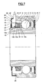
- the rolling bearing includes an outer ring 1 comprising on its bore a raceway 2 for rolling elements 3, for example balls, and an inner ring 4 provided with a raceway 5 for rolling elements 3.
- Rolling elements 3 are maintained circumferentially spaced by a cage 6.
- a seal 7 is provided on one side of the rolling bearing and secured to the outer ring 1 by means of a groove 8 disposed axially between the raceway 2 and a radial face of the outer ring 1.
- the outer ring 1 On the side opposite the seal 7, the outer ring 1 includes an axial extension 9 whose periphery 9a is diameter smaller than that of the periphery of the outer ring 1 and whose bore 9b is greater than the bore of the outer ring 1.
- the axial extension 9 ends with a radial front surface 9c.
- the inner ring 4 also includes an axial extension 10 arranged on the same side as the axial extension 9, of bore identical to that of the inner ring 4 and provided with a bearing rectified 10a on its outer surface.
- An encoder 11 is provided with an active part 12 produced by example of synthetic material charged with magnetic particles, and of a sheet metal support 13 on which the active part 12 is overmolded and comprising a cylindrical fitting part 13a and a flange radial 13b.
- the active part 12 includes an outer surface cylindrical 12a.
- a sensor 14 is mounted, integral with the outer ring 1, in look and at a short distance from the cylindrical surface 12a of the part activates 12 of encoder 11 to define a radial air gap 15.
- the sensor 14 is supported by a support 16 comprising a connection outlet 17 in which is mounted a cable 18 for communicating the information from the sensor, to the organs intended to to receive.
- the sensor support 16 is surrounded by a cover 19, made of sheet metal, provided with a cylindrical portion 20, one end of which is fitted on the periphery 9a of the extension 9 of the outer ring 1, and a radial portion 21 provided with a bore 22 allowing the connection outlet 17.
- the free end of the radial portion 22 supports a seal 23 which comes into friction contact with the cylindrical seat 10a of the extension 10 of the ring inner 4.
- the cover 19 defines with the outer rings 1 and interior 4 and rolling elements 3, an enclosed space, protected from external pollution, in which the encoder 11 and the sensor 14.
- the support 16 of the sensor 14 comprises a main body 24 axially disposed between the radial portion 21 of the cover 19 and the front surface 9c of the extension 9, and a retaining element 25 disposed axially between the main body 24 and the rolling elements 3, around the encoder 11.
- the main body 24 and the retaining element 25 are annular, except that the retaining element 25 is provided a receiving housing 26 for a sensor 14.
- the housing 26 is with oblique edges 27.
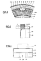
- the senor 14 is in the form of a component having a housing 28 provided with a reference face 29, an opposite detection face 30 at the reference face 29, two chamfers 31 arranged on the side and on the other side of the detection face 30, next to pins 32 from another face of the housing 28.
- the sensor 14 is arranged on the support 16 by a axial movement. We put the pins 32 in a passage 33 (figure 3) provided for this purpose and passing through the main body 24. At the end of the axial movement, the housing 28 is placed in the housing 26, the chamfers 31 of the detection face 30 coming to cooperate with the oblique surfaces 27, until the housing 28 abuts against the main body 24.
- the sensor is then secured to the support in this position, for example by means of a resin introduced into the connection outlet area 17.
- the housing 28 is is then in the position illustrated in FIGS. 2 and 5.
- the face of reference 29 of the housing 28 is oriented outside to come in contact by its edges with the bore 9b of the extension 9 which serves as reference surface.
- the reference face 29 is slightly protruding radially outward from the periphery of the retaining element 25.
- the support 16 of the sensor 14 is produced in a material with a certain flexibility. Support 16 is provided to be able to enter with only a very slight play in bore 9b.
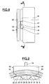
- the support 16 of sensor 14 is of the slide type, comprising two axial grooves 35 provided in the main body 24, on each edge of it and radially at the outer surface of the retaining element 25.
- the outer ring 1 is provided with a additional extension 36 axial and extending beyond the extension 9.
- the additional extension 36 is annular, only interrupted by a notch 37 provided with parallel edges 38 which cooperate with the grooves 35 of the support 16. It is ensured thus securing the support 16 and the outer ring 1.
- the connection outlet 17 is here radial, which makes it possible to decrease the axial size of the rolling bearing.
- the extension additional 36 of the outer ring 1 can be derived from this last and machined, or on the contrary added, for example by welding.
- the different elements are dimensioned so that after the establishment of the support 16 on the outer ring, the housing 28 of the sensor is pinched elastically between the oblique surfaces 27 of the retaining element 25 and the bore 9b of the outer ring, thus ensuring a rigorous air gap between sensor and encoder.
- the landing at bearing can also be provided with an outer ring rotating and a non-rotating inner ring.
Landscapes
- Engineering & Computer Science (AREA)
- General Engineering & Computer Science (AREA)
- Mechanical Engineering (AREA)
- Physics & Mathematics (AREA)
- General Physics & Mathematics (AREA)
- Rolling Contact Bearings (AREA)
- Transmission And Conversion Of Sensor Element Output (AREA)
Applications Claiming Priority (2)
| Application Number | Priority Date | Filing Date | Title |
|---|---|---|---|
| FR9705284 | 1997-04-29 | ||
| FR9705284A FR2762652B1 (fr) | 1997-04-29 | 1997-04-29 | Palier a roulement a capteur d'informations |
Publications (2)
| Publication Number | Publication Date |
|---|---|
| EP0875683A1 true EP0875683A1 (de) | 1998-11-04 |
| EP0875683B1 EP0875683B1 (de) | 2004-06-16 |
Family
ID=9506422
Family Applications (1)
| Application Number | Title | Priority Date | Filing Date |
|---|---|---|---|
| EP98401008A Expired - Lifetime EP0875683B1 (de) | 1997-04-29 | 1998-04-24 | Wälzlager mit Messwertgeber |
Country Status (5)
| Country | Link |
|---|---|
| US (1) | US6227710B1 (de) |
| EP (1) | EP0875683B1 (de) |
| JP (1) | JPH10311740A (de) |
| DE (1) | DE69824478T2 (de) |
| FR (1) | FR2762652B1 (de) |
Cited By (3)
| Publication number | Priority date | Publication date | Assignee | Title |
|---|---|---|---|---|
| EP1591765A4 (de) * | 2003-02-07 | 2006-05-24 | Koyo Seiko Co | Welzlagereinheit mit sensor |
| FR2900701A1 (fr) * | 2006-05-05 | 2007-11-09 | Skf Ab | Dispositif de commande de soupapes d'un moteur a combustion interne pourvu d'un roulement instrumente |
| US7654535B2 (en) | 2003-07-22 | 2010-02-02 | Cross Manufacturing Company (1938) Limited | Non-contacting face seals and thrust bearings |
Families Citing this family (17)
| Publication number | Priority date | Publication date | Assignee | Title |
|---|---|---|---|---|
| FR2792979B1 (fr) | 1999-04-28 | 2001-05-25 | Skf France | Palier a roulement a capteur d'informations |
| FR2806764B1 (fr) * | 2000-03-24 | 2002-08-23 | Skf France | Palier a roulement instrumente muni d'un dispositif d'etancheite |
| FR2807798B1 (fr) * | 2000-04-12 | 2002-07-26 | Skf France | Dispositif de detection de deplacement angulaire et palier a roulement instrumente |
| FR2810088B1 (fr) * | 2000-06-07 | 2004-06-04 | Skf France | Palier a roulement freine |
| NL1016756C2 (nl) * | 2000-11-30 | 2002-05-31 | Skf Eng & Res Centre Bv | Meetelement voor het meten van radiale en/of axiale krachten op een lager. |
| JP2003042150A (ja) * | 2001-07-31 | 2003-02-13 | Koyo Seiko Co Ltd | 転がり軸受装置 |
| JP2003074575A (ja) * | 2001-09-05 | 2003-03-12 | Koyo Seiko Co Ltd | 転がり軸受装置 |
| CN100436847C (zh) | 2001-11-22 | 2008-11-26 | 日本精工株式会社 | 带传感器的滚动轴承 |
| FR2839349B1 (fr) * | 2002-05-03 | 2004-11-19 | Skf Ab | Dispositif de galet a roulement instrumente |
| FR2843430B1 (fr) * | 2002-08-07 | 2005-03-18 | Roulements Soc Nouvelle | Systeme integre de fixation et de connection d'un capteur |
| EP1557676B1 (de) | 2002-10-28 | 2015-05-06 | NSK Ltd. | Rollenager mit sensor |
| DE112004001197T5 (de) * | 2003-07-04 | 2006-06-08 | Ntn Corp. | Radträger-Lager-Anordnung mit eingebautem Lastsensor |
| DE10338957A1 (de) * | 2003-08-25 | 2005-03-24 | Fag Kugelfischer Ag | Dichtungseinheit für eine Radlagerung |
| US20050117825A1 (en) * | 2003-11-26 | 2005-06-02 | Ntn Corporation | Wheel support bearing assembly with built-in sensor |
| US20070172163A1 (en) | 2004-02-17 | 2007-07-26 | Ntn Corporation | Bearing device with a sensor |
| TWI400438B (zh) * | 2010-04-01 | 2013-07-01 | Hiwin Tech Corp | 具檢測裝置之傳動元件 |
| DE102016223681A1 (de) * | 2016-11-29 | 2018-05-30 | Schaeffler Technologies AG & Co. KG | Klappenanordnung für ein Fahrzeug |
Citations (5)
| Publication number | Priority date | Publication date | Assignee | Title |
|---|---|---|---|---|
| EP0320322A2 (de) * | 1987-11-13 | 1989-06-14 | S.N.R. Roulements | Lager mit Magnetfelddetektor |
| US5017866A (en) * | 1990-02-08 | 1991-05-21 | The Torrington Company | Magnetic field sensor mounting with sensor arm contacting rotating bearing member |
| EP0495323A1 (de) * | 1991-01-15 | 1992-07-22 | Snr Roulements | Wälzlager mit Messaufnehmer |
| EP0511105A1 (de) * | 1991-04-24 | 1992-10-28 | Jaeger | Walzenlager mit Geschwindigkeitsmessaufnehmer |
| EP0631139A1 (de) * | 1993-06-24 | 1994-12-28 | Firma Carl Freudenberg | Dichtungsvorrichtung mit Messwertaufnehmer |
Family Cites Families (1)
| Publication number | Priority date | Publication date | Assignee | Title |
|---|---|---|---|---|
| US4875785A (en) * | 1987-11-13 | 1989-10-24 | The Torrington Company | Thrust bearing with a magnetic field detector |
-
1997
- 1997-04-29 FR FR9705284A patent/FR2762652B1/fr not_active Expired - Fee Related
-
1998
- 1998-04-24 DE DE69824478T patent/DE69824478T2/de not_active Expired - Fee Related
- 1998-04-24 EP EP98401008A patent/EP0875683B1/de not_active Expired - Lifetime
- 1998-04-28 JP JP10132610A patent/JPH10311740A/ja active Pending
- 1998-04-29 US US09/067,901 patent/US6227710B1/en not_active Expired - Fee Related
Patent Citations (5)
| Publication number | Priority date | Publication date | Assignee | Title |
|---|---|---|---|---|
| EP0320322A2 (de) * | 1987-11-13 | 1989-06-14 | S.N.R. Roulements | Lager mit Magnetfelddetektor |
| US5017866A (en) * | 1990-02-08 | 1991-05-21 | The Torrington Company | Magnetic field sensor mounting with sensor arm contacting rotating bearing member |
| EP0495323A1 (de) * | 1991-01-15 | 1992-07-22 | Snr Roulements | Wälzlager mit Messaufnehmer |
| EP0511105A1 (de) * | 1991-04-24 | 1992-10-28 | Jaeger | Walzenlager mit Geschwindigkeitsmessaufnehmer |
| EP0631139A1 (de) * | 1993-06-24 | 1994-12-28 | Firma Carl Freudenberg | Dichtungsvorrichtung mit Messwertaufnehmer |
Cited By (5)
| Publication number | Priority date | Publication date | Assignee | Title |
|---|---|---|---|---|
| EP1591765A4 (de) * | 2003-02-07 | 2006-05-24 | Koyo Seiko Co | Welzlagereinheit mit sensor |
| US7216551B2 (en) | 2003-02-07 | 2007-05-15 | Jtekt Corporation | Rolling bearing unit with sensor |
| CN100394189C (zh) * | 2003-02-07 | 2008-06-11 | 株式会社捷太格特 | 带传感器的滚动轴承单元 |
| US7654535B2 (en) | 2003-07-22 | 2010-02-02 | Cross Manufacturing Company (1938) Limited | Non-contacting face seals and thrust bearings |
| FR2900701A1 (fr) * | 2006-05-05 | 2007-11-09 | Skf Ab | Dispositif de commande de soupapes d'un moteur a combustion interne pourvu d'un roulement instrumente |
Also Published As
| Publication number | Publication date |
|---|---|
| EP0875683B1 (de) | 2004-06-16 |
| FR2762652A1 (fr) | 1998-10-30 |
| US6227710B1 (en) | 2001-05-08 |
| DE69824478T2 (de) | 2005-07-07 |
| FR2762652B1 (fr) | 1999-06-18 |
| JPH10311740A (ja) | 1998-11-24 |
| DE69824478D1 (de) | 2004-07-22 |
Similar Documents
| Publication | Publication Date | Title |
|---|---|---|
| EP0875683B1 (de) | Wälzlager mit Messwertgeber | |
| EP0821240B1 (de) | Wälzlager mit Messwertaufnehmer | |
| EP0647851B1 (de) | Kodierelement mit Messaufnehmer und damit angestattetem Lager | |
| EP0726468B1 (de) | Kodiervorrichtung für Geschwindigkeitsmessaufnehmer sowie ein mit einer solchen Vorrichtung versehenes Wälzlager | |
| EP0872652B1 (de) | Wälzlager mit Messwertenaufnehmer | |
| FR2851624A1 (fr) | Palier a roulement instrumente | |
| FR2813644A1 (fr) | Dispositif de palier a roulement instrumente, notamment pour volant de commande | |
| EP0521789A1 (de) | Dichte Messfühlereinheit zum Einbau in ein Lager und Lager mit einer derart ausgestatteten Einheit | |
| FR2792979A1 (fr) | Palier a roulement a capteur d'informations | |
| EP1366370B1 (de) | Rollenvorrichtung mit instrumentiertem wälzlager | |
| EP1252524B1 (de) | Instrumentierte lagervorrichtung mit temporärer winkelvorindexierung des kodierers gegenüber dem sensor | |
| EP1196787B1 (de) | Wälzlager mit messeinrichtung | |
| FR2806764A1 (fr) | Palier a roulement instrumente muni d'un dispositif d'etancheite | |
| FR2818708A1 (fr) | Bl0c porte-capteur et palier a roulement a capteur d'informations | |
| FR2836191A1 (fr) | Palier a roulement instrumente | |
| FR2823811A1 (fr) | Ensemble mecanique comprenant un palier a roulement instrumente | |
| WO2001094800A1 (fr) | Palier a roulement instrumente pour volant de commande | |
| EP1433968A1 (de) | Kompaktes Wälzlager mit Bremseinrichtung | |
| FR2823812A1 (fr) | Dispositif d'etancheite pour palier a roulement instrumente et palier a roulement instrumente | |
| FR2882139A1 (fr) | Dispositif de detection des parametres de rotation de deux elements | |
| FR2898949A1 (fr) | Dispositif de roulement instrumente. | |
| FR2851650A1 (fr) | Dispositif de detection de parametre de rotation et palier a roulement. | |
| FR2871881A1 (fr) | Dispositif de detection de parametres de rotation d'une roue notamment d'une roue de vehicule | |
| EP1359423A1 (de) | Rolle mit einem mit Drehgeschwindigkeitsaufnehmer versehenen Wälzlager | |
| EP1473570A1 (de) | Wälzager mit integrierter Geschwindigkeitsmessvorrichtung |
Legal Events
| Date | Code | Title | Description |
|---|---|---|---|
| PUAI | Public reference made under article 153(3) epc to a published international application that has entered the european phase |
Free format text: ORIGINAL CODE: 0009012 |
|
| AK | Designated contracting states |
Kind code of ref document: A1 Designated state(s): DE FR GB IT NL |
|
| AX | Request for extension of the european patent |
Free format text: AL;LT;LV;MK;RO;SI |
|
| 17P | Request for examination filed |
Effective date: 19981203 |
|
| AKX | Designation fees paid |
Free format text: DE FR GB IT NL |
|
| GRAP | Despatch of communication of intention to grant a patent |
Free format text: ORIGINAL CODE: EPIDOSNIGR1 |
|
| GRAS | Grant fee paid |
Free format text: ORIGINAL CODE: EPIDOSNIGR3 |
|
| GRAA | (expected) grant |
Free format text: ORIGINAL CODE: 0009210 |
|
| AK | Designated contracting states |
Kind code of ref document: B1 Designated state(s): DE FR GB IT NL |
|
| PG25 | Lapsed in a contracting state [announced via postgrant information from national office to epo] |
Ref country code: NL Free format text: LAPSE BECAUSE OF FAILURE TO SUBMIT A TRANSLATION OF THE DESCRIPTION OR TO PAY THE FEE WITHIN THE PRESCRIBED TIME-LIMIT Effective date: 20040616 |
|
| REG | Reference to a national code |
Ref country code: GB Ref legal event code: FG4D Free format text: NOT ENGLISH |
|
| GBT | Gb: translation of ep patent filed (gb section 77(6)(a)/1977) |
Effective date: 20040616 |
|
| REF | Corresponds to: |
Ref document number: 69824478 Country of ref document: DE Date of ref document: 20040722 Kind code of ref document: P |
|
| NLV1 | Nl: lapsed or annulled due to failure to fulfill the requirements of art. 29p and 29m of the patents act | ||
| PLBE | No opposition filed within time limit |
Free format text: ORIGINAL CODE: 0009261 |
|
| STAA | Information on the status of an ep patent application or granted ep patent |
Free format text: STATUS: NO OPPOSITION FILED WITHIN TIME LIMIT |
|
| PG25 | Lapsed in a contracting state [announced via postgrant information from national office to epo] |
Ref country code: IT Free format text: LAPSE BECAUSE OF NON-PAYMENT OF DUE FEES Effective date: 20050424 Ref country code: GB Free format text: LAPSE BECAUSE OF NON-PAYMENT OF DUE FEES Effective date: 20050424 |
|
| 26N | No opposition filed |
Effective date: 20050317 |
|
| PG25 | Lapsed in a contracting state [announced via postgrant information from national office to epo] |
Ref country code: DE Free format text: LAPSE BECAUSE OF NON-PAYMENT OF DUE FEES Effective date: 20051101 |
|
| GBPC | Gb: european patent ceased through non-payment of renewal fee |
Effective date: 20050424 |
|
| PGFP | Annual fee paid to national office [announced via postgrant information from national office to epo] |
Ref country code: FR Payment date: 20080417 Year of fee payment: 11 |
|
| REG | Reference to a national code |
Ref country code: FR Ref legal event code: ST Effective date: 20091231 |
|
| PG25 | Lapsed in a contracting state [announced via postgrant information from national office to epo] |
Ref country code: FR Free format text: LAPSE BECAUSE OF NON-PAYMENT OF DUE FEES Effective date: 20091222 |