EP0875809A2 - Appareil de CAD-CAM et appareil d'usinage - Google Patents
Appareil de CAD-CAM et appareil d'usinage Download PDFInfo
- Publication number
- EP0875809A2 EP0875809A2 EP98303193A EP98303193A EP0875809A2 EP 0875809 A2 EP0875809 A2 EP 0875809A2 EP 98303193 A EP98303193 A EP 98303193A EP 98303193 A EP98303193 A EP 98303193A EP 0875809 A2 EP0875809 A2 EP 0875809A2
- Authority
- EP
- European Patent Office
- Prior art keywords
- force
- work
- machining
- path data
- grinding
- Prior art date
- Legal status (The legal status is an assumption and is not a legal conclusion. Google has not performed a legal analysis and makes no representation as to the accuracy of the status listed.)
- Withdrawn
Links
Images


Classifications
-
- G—PHYSICS
- G05—CONTROLLING; REGULATING
- G05B—CONTROL OR REGULATING SYSTEMS IN GENERAL; FUNCTIONAL ELEMENTS OF SUCH SYSTEMS; MONITORING OR TESTING ARRANGEMENTS FOR SUCH SYSTEMS OR ELEMENTS
- G05B19/00—Program-control systems
- G05B19/02—Program-control systems electric
- G05B19/18—Numerical control [NC], i.e. automatically operating machines, in particular machine tools, e.g. in a manufacturing environment, so as to execute positioning, movement or co-ordinated operations by means of program data in numerical form
- G05B19/4097—Numerical control [NC], i.e. automatically operating machines, in particular machine tools, e.g. in a manufacturing environment, so as to execute positioning, movement or co-ordinated operations by means of program data in numerical form characterised by using design data to control NC machines, e.g. CAD/CAM
Definitions
- the present invention relates to a CAD/CAM apparatus and a machining apparatus.
- the invention is applicable to a CAD/CAM apparatus and a machining apparatus in which path data having position and force information or energy as attributes are calculated in accordance with a predetermined algorithm. The calculations are undertaken on the basis of shape information, machining information and machined surface information of a work to thereby perform force control in addition to positional control so that high quality and stable shape precision and surface roughness may be obtained.
- Fig. 9 shows a conventional CAM system.
- the shape of a work 3 is modelled by a CAD 1.
- the operation of defining surface information (recognising the portions surrounded by lines as surfaces) and defining coupling information of surfaces is performed together by the CAM.
- parameters such as a machining original point, an approach velocity, a pitch amount, a removal allowance, a tool to be used or the like (hereinafter referred to as machining information) are input into a tool path calculation section 5.
- Section 5 performs the calculation and compilation of the path. These operations are performed for every machining step (rough machining, intermediate machining and finishing).
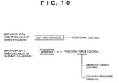
- an NC machining program (G-code, M-code) is automatically produced in a program producing section 7 in accordance with the path data calculated in the tool path calculation section 5. Since this program is output as a text file, it is possible to compile it by an editor. Subsequently, in accordance with the NC machining program produced in the program producing section 7, the establishment of target values for the positional and velocity control of the tool or the replacement of the tools are performed in a position/motion planning section 9. The work 3 is automatically machined by a positional control section 11. Since the conventional CAM system handles only the positional (and velocity) information; the system is suitable for cutting work (or grinding work) with high shape precision. As a matter of fact, almost all the CAM systems are used for cutting machining.
- a grinding unit 31 is a rotary type grinding machine such as a PVA (polyvinyl alcohol) grinding stone or a buff grinding unit.
- a buff 35 is driven by drivers 33a and 33b.
- the work 3 is held by a robot 39 and is depressed against the buff 35 by a force f(t) in a direction x to thereby grind a predetermined surface.
- the buff 35 is moved at a velocity V(t) in a direction y (where the velocity in the tangential direction of the buff 35 at a tangential point is defined at V(t)).
- t is the grinding time when the work 3 is depressed to the buff 35.
- the force f(t) (not shown) in the direction x which is given to the work 3 by the robot 39 is adjusted so that the force f(t) becomes a predetermined value.
- the frictional coefficient between the buff 35 and the work 3 is delicately changed in accordance with various conditions, it is not possible to perform stable grinding work in control of the force f nx (t) in the direction x by supervising the force f(t) in the direction x.
- the essence of the grinding work is in relation equal to the total amount of energy given from the grinding unit 31 (hereinafter simply referred to a grinding energy).
- the reason why the control should increase the force f(t) or to elongate the grinding time t when the above-described clogging occurs is that it is necessary to keep the grinding energy constant. In order to obtain a high quality and stable ground surface without any adverse affect by the change in frictional coefficient, it is ideal to control the grinding energy by the robot 39.
- an object of the present invention is to provide a CAD/CAM apparatus and a machining apparatus in which path data having position and force information or energy as attributes are calculated in accordance with a predetermined algorithm. The calculations are undertaken on the basis of shape information, machining information and machined surface information of the work to thereby perform force control in addition to positional control so that high quality and stable shape precision and surface roughness may be obtained.
- a CAD/CAM apparatus comprises a path data calculation means for calculating path data having as an attribute at least one of a position, a force and an energy on the basis of shape information of a work, machining information including a parameter needed for machining the work and machined surface information representing a state of a machined surface of the work; and an operation planning calculation means for calculating an operation plan of the path on the basis of the path data calculated by the path data calculation means.
- the path data calculation means calculates the path data having as an attribute at least one of a position, a force and an energy on the basis of shape information of a work (3), machining information including a parameter needed for machining the work (3) and machined surface information representing a state of a machined surface of the work (3).
- the machining method is such that the work (3) or the tool is moved.
- the path means the path of the tool or the work (3).
- the operation planning calculation means (19) calculates an operation plan for the path on the basis of the path data calculated by the path data calculation means (15).
- the path data calculation means (15) produces a predetermined function on the basis of an algorithm in which the skill of a skilled artisan is reflected with respect to at least one of the shape information, the machining information and the machined surface information of the work (3).
- the calculation means (15) calculates the path data on the basis of the function.
- the algorithm which reflects the skill of the skilled artisan concerning the shape information, machining information and machined surface information of the work (3) is produced.
- a predetermined function is produced on the basis of this algorithm.
- the position and/or force data are calculated and output on the basis of the function.
- the data of the position and/or force sought in the path data calculation means (15) may reflect the skill of the artisan and the skill owned by the artisan may be realised in a very effective manner.
- a grinding unit (31) for grinding a predetermined surface of the work (3) at a tangential velocity V(t) and a robot (39) for pressing the work (3) against the grinding unit (31) with a contact area A or for pressing the grinding unit (31) against the work (3) fixed at a predetermined position in a space.
- the arrangement is characterised in that force control is performed so that the grinding energy needed for grinding the work (3) becomes an energy having a value E (t) sought by the path data.
- the total amount of the grinding energy needed for grinding the work (3) and given to the work (3) by the robot (39) is under a one-to-one relation with the grinding amount. Accordingly, in order to keep constant the ground surface, it is necessary to control the grinding energy at a desired value predetermining the grinding energy. Thus, it is possible to obtain a ground surface with a high quality and stability without any adverse affect by the change of the frictional coefficient.
- the work (3) may be held by the robot (39) and the work (3) may be pressed against the grinding unit.
- the grinding unit (31) is held by the robot (39) and the grinding unit (31) may be pressed to the work (3) fixed in a space.
- Fig. 1 shows a CAM system for processing position and force information.
- the same references are used to indicate the same components as those shown in Fig. 9 and duplicate explanation therefor will be omitted.
- path data having position and force information as an attribute is calculated.
- the calculation is made, for example, by a fuzzy inference from machined surfaced information and machining information given by the conditions between the work 3 and the tool to be used and the shape information given by the CADI.
- the machining program producing section 17 the machining program is produced on the basis of the path data.
- the position/force operation planning section 19 a target orbit concerning the force/moment is designed together with the position/posture target orbit as a cubic polynomial or a quintic polynomial.
- the path calculation section 15, the machining program producing section 17 and the position/force operation planning section 19 constitute a CAM 2.
- the orbit data for every renewal cycle Tm are calculated by using the polynomial obtained in the position/force operation planning section 19.
- the position and the frictional force are simultaneously fed back on the basis of the orbit data obtained in the position/force orbit producing section 21.
- a three-dimensional shape modelled by the CAD 1 is input into the path calculation section 15. Then, the three-dimensional shape is used for the operation plan of the position as the machining shape information. Also, the ground surface area of the work 3 and the machining information such as the current surface roughness are given as the machined surface information by the parameter input.
- the position/force information is processed by the fuzzy inference on the basis of the machined surface information, the machining information and the machining shape information.
- the fuzzy rule is produced concerning the items relating to the position/force. grinding energy En ground surface area A large medium small current surface roughness - target surface roughness e large large (1) large (2) medium (3) medium large (4) medium (5) small (6) small medium (7) small (8) small (9)
- the grinding energy for example, if the difference between the target surface roughness and the current surface roughness is large and the ground surface area is large, the grinding energy (frictional force) is increased.
- the rule reflects the skill of a skilled artisan.
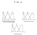
- Table 1 the difference between the target surface roughness and the current surface roughness and the ground surface area are classified into three stages, respectively. Also the energy, which is the evaluation item, is classified into three stages. However, it is possible to perform the control in more detail by increasing the number of stages. Then, subsequently, the membership function is produced on the basis of the fuzzy rule of Table 1. As shown in Fig.
- the membership function representing the magnitudes, such as, "large”, “medium” and “small” concerning the surface roughness difference e, the ground surface area A and the grinding energy En is produced.
- the ordinate represents the suitability, 0 means not suitable, and 1 represents very good suitability.
- Fig. 3 shows graphs of the fuzzy inference method.
- the respective determined values are input with respect to the membership function of the surface roughness difference e and the ground surface area A. Subsequently, the degree of matching between the membership function of the ground surface area A and the surface roughness difference e with respect to the respective rule of (1) to (9) of Table 1 is searched. The membership function of the grinding energy En is removed on the side of the smaller value. Then, the rest thereof is adopted to obtain the inference result.
- the suitability of the determined value input for the surface roughness difference e is 0.5.
- the suitability of the determined value input for the ground surface area A is 0.6. Accordingly, the value 0.5 that is the smaller value of the suitability is adopted as the suitability for the grinding energy En. Then, the membership function of the grinding energy En is removed by the suitability 0.5, and the rest thereof is adopted. In the same way, also with respect to the rules other than rule (2), the fuzzy inference is performed. However, in the rules other than those shown in Fig. 2, the matching degree is zero. Therefore, these cases are omitted.
- the calculated grinding energy En takes a logic sum over all the rules. Thereafter, the gravitational centre position is sought for all the surface of the grinding energy En taking the logic sum. The gravitational centre position is the determined value for the desired grinding energy.
- the determined value is calculated with respect to the grinding energy. Also, in the same manner, the determined values may be calculated for the force or the moment. In the foregoing steps, the fuzzy inference is adopted as the algorithm. The method of calculating the determined values is not limited to that just described.
- the position/force operation planning section 19 realises the operation plan of the robot or the like for the hybrid control system of position and force.
- the target orbit concerning the force/moment is designed as the cubic polynomial or the quintic polynomial together with the position/posture target orbit to realise the desired force/moment that is manually applied to the object in the actual operation.
- the frictional force F(t) is sought as the target orbit function on the basis of the following formula 1, so that the grinding energy E (t) becomes the grinding energy determined value.
- V(t) is the velocity of the grinding unit or the tool on the contact surface.
- the target orbit or the target position/posture data or the like is obtained by giving the target operation time to the determined target orbit function.
- the "orbit production” means a process for producing the target orbit data by using the target orbit function.
- the motion rate is generally set to an integer times the servo rate (control sampling time).
- the simultaneous feedback control of the position and the frictional force is performed on the basis of the target position and posture data or the like given in the position/force orbit producing section 21.
- the machining data such as the grinding, cutting and finishing with great account of the surface roughness are output to produce the operation plan or the orbit and control of the working machine. Accordingly, it is possible automatically to perform the operation.
- the path calculation section 15, the machining program producing section 17 and the position/force operation planning section 19 are formed independently of the CAD 1.
- the CAD 1, the path calculation section 15, the machining program producing section 17 and the position/force operation planning section 19 constitute the CAM 2.
- the structure of the embodiment is the same as that shown in Fig. 11.
- the buff 35 is moved in the direction y at the tangential directional velocity V(t) (hereinafter simply referred to as a grinding velocity) by the grinding unit 31.
- the robot 39 presses the work 3 to the buff 35 by the force f(t) in the direction x.
- the grinding energy E(t) per unit area is given by the formula 1.
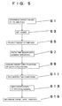
- step S3 the target value is set as a node together with the time when the target value is applied.
- the node is determined for each degree of freedom of control. For example, in the graph of F(t) shown in Fig.
- step S5 the node is projected to the time axis.
- the projected node is represented as the logic sum for each degree of freedom of control.
- step S7 the time region is divided by the same number as that of the nodes.
- the minimum unit of operation in the divided time region is regarded as an "element operation”.
- the target orbit function in the element operation is designed.
- the target orbit function is designed as the quintic polynomial as shown in Fig. 6(a) but it is possible to design it as the cubic polynomial.
- three functions are assumed.
- One function corresponds to a first differentiation of another function.
- step S11 the restrictive conditions are given to the three functions.
- the number of the restrictive conditions is six as shown in Fig.
- step S13 it is possible to determine the target orbit function as shown in Fig. 6(c).
- the restrictive conditions that are to be boundary are given and the target orbit function is solved so that the target orbit of the frictional force F 1 (t) and the target position P ry (t) may be smoothly connected as shown in Fig. 4. Accordingly, there is no shock and also there is none of residual vibration or deformation or damage or the like. If the quintic polynomial is designed, it is possible to realise the function more similar to the human operation than the cubic polynomial.
- the control system model is shown in Fig. 7.
- Fig. 7 the control on the robotic side in the case where the robot 39 (not shown in Fig. 7) presses the work 3 having a mass m against the grinding unit 31 having the elastic coefficient k will be described.
- P x is the position in the direction x
- P y is the position in the direction y
- f x is the force given in the direction x by the grinding unit 31
- f y is the frictional force in the direction y
- f mx is the drive force given in the direction x by the robot 39
- f my is the drive force given in the direction y by the robot 39
- Pry is the target value for the direction y of the work 3.
- the respective equations of motion in the directions x and y are given by formula 7:
- the system is designed so that a compensator is constituted by C x (s), C y (s) and an assistant input (mg+f y ) whereby a closed loop system is stabilised.
- the structure of the compensator may be based upon a classic control logic such as a PID control or the like or may be based upon a current control/robust control theory.
- the path data having positional information, force information and energy as attributes are calculated by a predetermined algorithm on the basis of the shape information, machining information and machined surface information of the work. Accordingly, force control may be performed in addition to positional control to thereby perform the machining of high quality and stable shape precision and described surface roughness.
Landscapes
- Engineering & Computer Science (AREA)
- Human Computer Interaction (AREA)
- Manufacturing & Machinery (AREA)
- Physics & Mathematics (AREA)
- General Physics & Mathematics (AREA)
- Automation & Control Theory (AREA)
- Manipulator (AREA)
- Numerical Control (AREA)
- Feedback Control In General (AREA)
- Automatic Control Of Machine Tools (AREA)
Applications Claiming Priority (6)
| Application Number | Priority Date | Filing Date | Title |
|---|---|---|---|
| JP12493297 | 1997-04-28 | ||
| JP9124932A JP2982060B2 (ja) | 1997-04-28 | 1997-04-28 | 研磨エネルギー制御装置 |
| JP124932/97 | 1997-04-28 | ||
| JP309743/97 | 1997-10-24 | ||
| JP30974397A JPH11123657A (ja) | 1997-10-24 | 1997-10-24 | 力情報を考慮したcad/cam装置及び加工装置 |
| JP30974397 | 1997-10-24 |
Publications (2)
| Publication Number | Publication Date |
|---|---|
| EP0875809A2 true EP0875809A2 (fr) | 1998-11-04 |
| EP0875809A3 EP0875809A3 (fr) | 2000-09-06 |
Family
ID=26461486
Family Applications (1)
| Application Number | Title | Priority Date | Filing Date |
|---|---|---|---|
| EP98303193A Withdrawn EP0875809A3 (fr) | 1997-04-28 | 1998-04-24 | Appareil de CAD-CAM et appareil d'usinage |
Country Status (2)
| Country | Link |
|---|---|
| US (1) | US6298279B1 (fr) |
| EP (1) | EP0875809A3 (fr) |
Cited By (3)
| Publication number | Priority date | Publication date | Assignee | Title |
|---|---|---|---|---|
| CN104875104A (zh) * | 2015-05-14 | 2015-09-02 | 常州大思世成机电科技有限公司 | 基于cad/cam技术的轮毂不规则曲面抛光方法 |
| CN108873817A (zh) * | 2018-05-04 | 2018-11-23 | 东南大学 | 一种回转体零件渐进成形的路径参数化的方法 |
| CN109590812A (zh) * | 2018-11-27 | 2019-04-09 | 苏州大学 | 使用气囊抛光处理非球面的路径生成方法 |
Families Citing this family (13)
| Publication number | Priority date | Publication date | Assignee | Title |
|---|---|---|---|---|
| JP3435117B2 (ja) * | 2000-03-09 | 2003-08-11 | 義昭 垣野 | 加工制御システム |
| JP3490962B2 (ja) * | 2000-08-11 | 2004-01-26 | スター精密株式会社 | 工具軌跡作成方法及び加工方法 |
| JP4210056B2 (ja) * | 2001-12-25 | 2009-01-14 | 株式会社日立製作所 | 工具経路の作成装置及び方法 |
| DE10308292B4 (de) * | 2003-02-26 | 2007-08-09 | Erwin Junker Maschinenfabrik Gmbh | Verfahren zum Rundschleifen bei der Herstellung von Werkzeugen aus Hartmetall und Rundschleifmaschine zum Schleifen von zylindrischen Ausgangskörpern bei der Herstellung von Werkzeugen aus Hartmetall |
| DE102004009352B4 (de) * | 2004-02-26 | 2006-01-19 | Thyssen Krupp Automotive Ag | Vorrichtung zum Herstellen einer Fertigkontur eines Werkstücks durch Schleifen und Verfahren dazu |
| DE102005035474B4 (de) * | 2005-07-28 | 2019-06-13 | Institut Straumann Ag | Verfahren zum Herstellen von Zahnersatzteilen, Computer, Computerprogramm und computerlesbares Medium |
| US7930058B2 (en) * | 2006-01-30 | 2011-04-19 | Memc Electronic Materials, Inc. | Nanotopography control and optimization using feedback from warp data |
| US8214178B2 (en) * | 2008-06-04 | 2012-07-03 | Vibration Technologies, Llc | Method and system for optimizing the vibrational characteristics of a structure |
| US9579824B2 (en) | 2010-12-07 | 2017-02-28 | Sky Climber Field Services, Llc | Method and system for mortar removal |
| US8527103B2 (en) | 2010-12-07 | 2013-09-03 | Sky Climber Field Services, Llc | Method and system for mortar removal |
| US20160046010A1 (en) * | 2012-06-29 | 2016-02-18 | Black & Decker Inc. | System for enhancing operation of power tools |
| CN103971019B (zh) * | 2014-05-23 | 2017-02-08 | 武汉科技大学 | 一种基于几何特征的工件加工能耗预测方法 |
| JP6762003B2 (ja) | 2016-02-29 | 2020-09-30 | 国立大学法人神戸大学 | 物体表面修正方法およびワークの加工方法 |
Family Cites Families (8)
| Publication number | Priority date | Publication date | Assignee | Title |
|---|---|---|---|---|
| GB2054199B (en) * | 1979-06-14 | 1983-10-05 | Daihatsu Motor Co Ltd | Numerically controlled machine tool |
| GB2202659B (en) * | 1987-02-23 | 1991-07-17 | Mitutoyo Corp | Coordinate measuring instrument and method of generating pattern data concerning shape of work to be measured |
| US5198984A (en) * | 1988-08-31 | 1993-03-30 | Okuma Corporation | Numerical control method for correcting machine tool path errors |
| US5005135A (en) * | 1989-03-22 | 1991-04-02 | Cincinnati Milacron, Inc. | Dynamic correction of servo following errors in a computer-numerically controlled system and fixed cycle utilizing same |
| US5761390A (en) * | 1991-12-12 | 1998-06-02 | Hitachi, Ltd. | Robot for removing unnecessary portion on workpiece |
| EP0865871B1 (fr) * | 1992-06-24 | 2003-01-15 | Hoya Corporation | Production de verres de lunettes |
| US5419222A (en) * | 1992-10-08 | 1995-05-30 | The United States Of America As Represented By The United States Department Of Energy | Method for measuring the contour of a machined part |
| JPH0819918A (ja) * | 1994-07-07 | 1996-01-23 | Mitsubishi Electric Corp | ワイヤ放電加工方法及びその装置 |
-
1998
- 1998-04-24 EP EP98303193A patent/EP0875809A3/fr not_active Withdrawn
- 1998-04-27 US US09/067,850 patent/US6298279B1/en not_active Expired - Fee Related
Non-Patent Citations (5)
| Title |
|---|
| LIU M -H: "ENTWICKLUNG EINES KRAFTGEREGELTEN ROBOTERENTGRATSYSTEMS MIT HILFE VON FUZZY-LOGIK" AUTOMATISIERUNGSTECHNIK - AT,DE,OLDENBOURG VERLAG. MUNCHEN, vol. 42, no. 5, 1 May 1994 (1994-05-01), pages 218-224, XP000446994 ISSN: 0178-2312 * |
| MAHADEV P S ET AL: "BRUSH FINISHING AND POLISHING: A TECHNOLOGY REVIEW" MANUFACTURING REVIEW,US,AMERICAN SOCIETY OF MECHANICAL ENGINEERS, NEW YORK, vol. 4, no. 4, 1 December 1991 (1991-12-01), pages 246-256, XP000241550 ISSN: 0896-1611 * |
| ONG S . K., NEE A. Y. C.: "PROCESS MODELLING AND FORMULATION FOR THE DEVELOPMENT OF AN INTELLIGENT SET-UP PLANNING SYSTEM" PROCEEDINGS OF THE INSTITUTION OF MECHANICAL ENGINEERS. JOURNAL OF ENGINEERING MANUFACTURE, vol. 209, no. B1, 1995, pages 455-467, XP000923080 UK * |
| ROWE W B Y ET AL: "Application of intelligent CNC in grinding" COMPUTERS IN INDUSTRY,NL,ELSEVIER SCIENCE PUBLISHERS. AMSTERDAM, vol. 31, no. 1, 30 October 1996 (1996-10-30), pages 45-60, XP004013564 ISSN: 0166-3615 * |
| SONG K -T ET AL: "A FUZZY ADAPTIVE CONTROL DESIGN FOR COMPLIANT MOTION OF A MANIPULATOR" PROCEEDINGS OF THE INTERNATIONAL CONFERENCE ON INDUSTRIAL ELECTRONICS,CONTROL AND INSTRUMENTATION. (IECON),US,NEW YORK, IEEE, vol. CONF. 20, 1994, pages 703-707, XP000525404 ISBN: 0-7803-1329-1 * |
Cited By (4)
| Publication number | Priority date | Publication date | Assignee | Title |
|---|---|---|---|---|
| CN104875104A (zh) * | 2015-05-14 | 2015-09-02 | 常州大思世成机电科技有限公司 | 基于cad/cam技术的轮毂不规则曲面抛光方法 |
| CN108873817A (zh) * | 2018-05-04 | 2018-11-23 | 东南大学 | 一种回转体零件渐进成形的路径参数化的方法 |
| CN109590812A (zh) * | 2018-11-27 | 2019-04-09 | 苏州大学 | 使用气囊抛光处理非球面的路径生成方法 |
| CN109590812B (zh) * | 2018-11-27 | 2019-11-29 | 苏州大学 | 使用气囊抛光处理非球面的路径生成方法 |
Also Published As
| Publication number | Publication date |
|---|---|
| US6298279B1 (en) | 2001-10-02 |
| EP0875809A3 (fr) | 2000-09-06 |
Similar Documents
| Publication | Publication Date | Title |
|---|---|---|
| EP0875809A2 (fr) | Appareil de CAD-CAM et appareil d'usinage | |
| US5923561A (en) | Process of generating a succession of discrete points defining cutter path, by calculating a space interval of discrete points | |
| US9423788B2 (en) | Automatic method for milling complex channel-shaped cavities | |
| Hu et al. | Implementation of a robot system for sculptured surface cutting. Part 1. Rough machining | |
| US20030125829A1 (en) | NC program generating method, NC program generating apparatus, computer memory product, and computer program product | |
| JP7382537B2 (ja) | スマートコーナ切断のための方法、コンピュータプログラムおよびレーザ切断システム | |
| US20190086898A1 (en) | Software module, precision machine, method and component | |
| Jerard et al. | On-line optimization of cutting conditions for NC machining | |
| KR100569049B1 (ko) | 재료 제거에 의한 작업 대상물 가공 방법 | |
| Wang et al. | Force control technologies for new robotic applications | |
| Wang et al. | A Methodology to Support Robotic Polishing of Molds Integrated with CAD/CAM | |
| US9927801B2 (en) | Automatic method for milling complex channel-shaped cavities via coupling flank-milling positions | |
| US12409522B2 (en) | Device and method for machining a workpiece | |
| Wang et al. | A metric-based approach to 2D tool-path optimization for high-speed machining | |
| Iuvshin et al. | Development of Complex Surfaces Adaptive Polishing Method for Robotic Cell | |
| CN114217572B (zh) | 一种基于cam的时间样条曲面生成方法 | |
| Teltz et al. | Intelligent, open architecture control for machining systems | |
| Frank et al. | Rapid prototyping using CNC machining | |
| JP2865213B2 (ja) | 数値制御情報作成装置 | |
| Kim et al. | Robust coordination control of a pneumatic deburring tool | |
| JPH07256537A (ja) | 加工インピーダンス制御方法 | |
| Sata et al. | Manufacturing preparation by use of product model in computer | |
| Marty et al. | Numerical simulation of a turning operation | |
| TOOLS | 2 MECHATRONIC SYSTEMS TECHNIQUES | |
| Wong et al. | Mechatronic systems techniques in computer numerical control of machine tools |
Legal Events
| Date | Code | Title | Description |
|---|---|---|---|
| PUAI | Public reference made under article 153(3) epc to a published international application that has entered the european phase |
Free format text: ORIGINAL CODE: 0009012 |
|
| AK | Designated contracting states |
Kind code of ref document: A2 Designated state(s): AT BE CH CY DE DK ES FI FR GB GR IE IT LI LU MC NL PT SE |
|
| AX | Request for extension of the european patent |
Free format text: AL;LT;LV;MK;RO;SI |
|
| PUAL | Search report despatched |
Free format text: ORIGINAL CODE: 0009013 |
|
| AK | Designated contracting states |
Kind code of ref document: A3 Designated state(s): AT BE CH CY DE DK ES FI FR GB GR IE IT LI LU MC NL PT SE |
|
| AX | Request for extension of the european patent |
Free format text: AL;LT;LV;MK;RO;SI |
|
| AKX | Designation fees paid | ||
| REG | Reference to a national code |
Ref country code: DE Ref legal event code: 8566 |
|
| STAA | Information on the status of an ep patent application or granted ep patent |
Free format text: STATUS: THE APPLICATION IS DEEMED TO BE WITHDRAWN |
|
| 18D | Application deemed to be withdrawn |
Effective date: 20010307 |