EP0875913A2 - Temperaturschalteranordnung - Google Patents
Temperaturschalteranordnung Download PDFInfo
- Publication number
- EP0875913A2 EP0875913A2 EP98630014A EP98630014A EP0875913A2 EP 0875913 A2 EP0875913 A2 EP 0875913A2 EP 98630014 A EP98630014 A EP 98630014A EP 98630014 A EP98630014 A EP 98630014A EP 0875913 A2 EP0875913 A2 EP 0875913A2
- Authority
- EP
- European Patent Office
- Prior art keywords
- switch
- blade actuator
- actuator
- switch blade
- shape memory
- Prior art date
- Legal status (The legal status is an assumption and is not a legal conclusion. Google has not performed a legal analysis and makes no representation as to the accuracy of the status listed.)
- Withdrawn
Links
Images


Classifications
-
- H—ELECTRICITY
- H01—ELECTRIC ELEMENTS
- H01H—ELECTRIC SWITCHES; RELAYS; SELECTORS; EMERGENCY PROTECTIVE DEVICES
- H01H37/00—Thermally-actuated switches
- H01H37/02—Details
- H01H37/32—Thermally-sensitive members
- H01H37/323—Thermally-sensitive members making use of shape memory materials
-
- H—ELECTRICITY
- H01—ELECTRIC ELEMENTS
- H01M—PROCESSES OR MEANS, e.g. BATTERIES, FOR THE DIRECT CONVERSION OF CHEMICAL ENERGY INTO ELECTRICAL ENERGY
- H01M50/00—Constructional details or processes of manufacture of the non-active parts of electrochemical cells other than fuel cells, e.g. hybrid cells
- H01M50/50—Current conducting connections for cells or batteries
- H01M50/572—Means for preventing undesired use or discharge
- H01M50/574—Devices or arrangements for the interruption of current
-
- H—ELECTRICITY
- H01—ELECTRIC ELEMENTS
- H01M—PROCESSES OR MEANS, e.g. BATTERIES, FOR THE DIRECT CONVERSION OF CHEMICAL ENERGY INTO ELECTRICAL ENERGY
- H01M50/00—Constructional details or processes of manufacture of the non-active parts of electrochemical cells other than fuel cells, e.g. hybrid cells
- H01M50/50—Current conducting connections for cells or batteries
- H01M50/572—Means for preventing undesired use or discharge
- H01M50/574—Devices or arrangements for the interruption of current
- H01M50/581—Devices or arrangements for the interruption of current in response to temperature
-
- Y—GENERAL TAGGING OF NEW TECHNOLOGICAL DEVELOPMENTS; GENERAL TAGGING OF CROSS-SECTIONAL TECHNOLOGIES SPANNING OVER SEVERAL SECTIONS OF THE IPC; TECHNICAL SUBJECTS COVERED BY FORMER USPC CROSS-REFERENCE ART COLLECTIONS [XRACs] AND DIGESTS
- Y02—TECHNOLOGIES OR APPLICATIONS FOR MITIGATION OR ADAPTATION AGAINST CLIMATE CHANGE
- Y02E—REDUCTION OF GREENHOUSE GAS [GHG] EMISSIONS, RELATED TO ENERGY GENERATION, TRANSMISSION OR DISTRIBUTION
- Y02E60/00—Enabling technologies; Technologies with a potential or indirect contribution to GHG emissions mitigation
- Y02E60/10—Energy storage using batteries
Definitions
- Shape memory alloys can be used to replace bimetals in thermal switches.
- a switch contact arm of shape memory alloy has a deformed shape at normal temperatures and changes to a recovered shape at elevated temperatures. These changes in shape of a shape memory alloy contact arm provide different contact arm positions that can be used to open and close an electrical circuit.
- Thermal switches for use in preventing thermal runaway in batteries must have a very low resistance so they will not be too wasteful of energy during normal charging and discharging of the battery. It is difficult to achieve low resistance with a current carrying actuator of shape memory metal. For protecting batteries against thermal runaway, it also is desirable that the protective switch function as a one-shot fuse that will not reclose once it has opened.
- a self-contained sealed thermal switch assembly includes a contact member of shape memory alloy sandwiched between a pair of electrically conductive metal outer members.
- the contact member has a contact arm that completes or opens a current path between the pair of outer members by changing between a deformed shape at normal temperatures and a recovered shape at an elevated temperature.
- a switch with a current carrying actuator of shape memory metal that responds to an overcurrent or overtemperature condition has a resistance less than 20 milliohms, more preferably less than 12 milliohms and most preferably less than about 5-7 milliohms.
- a switch having a current carrying actuator of shape memory metal operates as a oneshot fuse by moving to a switch open position at an elevated temperature and remaining open even though the temperature returns to normal.
- a switch having a current carrying actuator of shape memory metal includes an improved dielectric spacer sandwiched with an actuator mounting portion between a pair of metal plates.
- the spacer is a very hard electrical insulating material with high tensile strength, low water absorption and a high heat deflection temperature.
- the current carrying actuator of shape memory metal is deformed to a strain that is less than 8% and most preferably not greater than about 4%.
- low resistance is obtained by coating all current carrying metal parts of the switch. including both outer and peripheral surfaces thereof, with a precious metal.
- the contact member of shape memory alloy is substantially E-shaped in plan view, and the elongated contact arm is defined by the center leg of the E.
- the peripheral portion of the contact member is circumferentially interrupted so that its circumferential extent is substantially less than 360° but at least 270°.
- An electrical insulator is positioned between a peripheral portion of the contact member and one of the outer members.
- the contact arm engages the one outer member when it is in its deformed shape at normal temperatures, and moves out of engagement with the one outer member when it is in its recovered shape at an elevated temperature.
- the pair of outer members have a cavity therebetween in which the elongated contact arm is located, and the one outer member has a depression therein facing the cavity.
- the outer members have outwardly extending circumferential flanges surrounded by a sealing ring of electrical insulating material.
- a metal clamping ring surrounds the sealing ring and is crimped over the flanges on the outer members for holding same together while firmly compressing the sealing ring against the flanges to seal the cavity.
- the pair of outer members include a cap member and a base member.
- the base member is of aluminum and the cap member is of cold rolled steel that is plated with a precious metal.
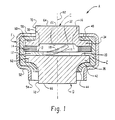
- Figure 1 shows a self-contained sealed thermal switch assembly A constructed in accordance with the present application.
- a current carrying actuator and contact B of shape memory alloy has a peripheral portion 12 thereof sandwiched between a pair of electrically conductive metal outer members C and D that respectively are identified as cap and base members.
- a dielectric gasket ring or spacer 14 is positioned between cap member C and peripheral portion 12 of contact member B.
- Ring 14 preferably is a relatively hard material such as a liquid crystal polymer, although it will be appreciated that other materials can be used.
- Dielectric spacer 14 preferably is of a relatively hard material that has a high tensile strength, low water absorption and a high heat deflection temperature.
- the material preferably has a tensile strength of at least 15,000 psi and more preferably at least 20,000 psi.
- the heat deflection temperature at 264 psi preferably is at least 500°F.
- the water absorption after 24 hours at 73°F is preferably not greater than about 0.02%.
- Dielectric spacer 14 may be made of many different materials having these desirable properties and one example is glass filled polyphenylenesulfide.
- One suitable material is available from General Electric Company under the name SupecG410T.
- Another suitable material is available from RTP Co. under the name RTP1300 P-1 series.
- Another material available from General Electric Company is Valox EF4530 PBTP Resin. All of these materials are glass reinforced and other materials having these desirable properties also are available.
- a central cavity 16 between outer members C and D receives an elongated contact arm 18 extending inwardly from outer peripheral portion 12 of contact member B.
- Arm 18 also defines a current carrying actuator of shape memory metal.
- Base outer member D has a substantially flat or plane inner surface 20 facing cavity 16.
- Cap outer member C also has a substantially flat or plane inner surface 22 facing cavity 16.
- Inner surface 22 also defines the bottom of a cavity or depression 30 in cap member C that enlarges the vertical extent of cavity 16.
- Contact arm 18 has a terminal end 32 engaging inner surface 22 on cap member C to provide an electric current path between outer members C and D.
- Outer members C and D have outwardly extending circumferential flanges 34 and 36 thereon to provide clamping surfaces for cooperation with a clamping ring, and are surrounded by a sealing ring E of electrical insulating material.
- Ring E preferably is of a relatively soft material that will deform and flow under load to provide a good seal. Polypropylene is one example of a material that can be used, although it will be appreciated that many other materials also would be satisfactory.
- Sealing ring E has inwardly extending upper and lower circumferential projections 40 and 42 that overlie flanges 34 and 36. Lower projection 42 extends inwardly and downwardly to terminate in a cylindrical portion 44.
- a metal clamping ring F surrounds sealing ring E and has inwardly extending circumferential extensions 50 and 52 that respectively overlie outer surfaces of circumferential sealing projection 40 and flange 34. and circumferential sealing projection 42 and flange 36.
- Clamping ring extension 52 extends inwardly and downwardly to terminate in a cylindrical clamping ring portion 54.
- Clamping ring F is crimped, along with its extensions 50 and 52, to compress sealing projections 40 and 42 against flanges 34 and 36 for providing a good seal between the surfaces generally indicated at 60 and 62.
- Insulating ring 14 and peripheral portion 12 of contact member B are held under compression by crimp ring F.
- Insulating ring 14 has a larger diameter than the outer periphery of contact member B, and of flanges 34 and 36. The outer periphery of ring 14 will engage sealing member E to prevent sliding movement of ring 14 relative to contact member B, and thereby prevent ring 14 from interfering with movement of switch arm 18.
- Outer members C and D have substantially flat circular outer end surfaces 64 and 66 that are located axially outwardly from clamping ring F.
- Outer members C and D have cylindrical outer end portions 70 and 72, and cylindrical outer end portion 72 on base outer member D has a slightly smaller diameter than cylindrical outer end portion 70 on cap outer member C.
- the diameter of cylindrical outer end portion 72 on base outer member D may be about 15-25 percent smaller than the diameter of cylindrical outer end portion 70 on cap outer member C.
- Contact member B preferably is of a nickel-titanium shape memory alloy.
- shape memory alloys can be used such as copper-based ternaries including copper-zinc-aluminum and copper-nickel-aluminum.
- the transition temperature range at which the alloy changes from its deformed shape to its recovered shape also can be varied significantly by selecting different shape memory alloy compositions and by varying heat treating processes.
- Contact member B is stamped and cut to its flat E-shaped configuration shown in Figure 2. and is then heated to its austenitic transformation temperature. The contact member is then cooled to the martensitic state of the alloy, and current carrying contact arm actuator 18 is bent to a deformed shape having a desired configuration and position.
- This deformed shape is the one generally shown in Figure 1, and the relaxed deformed shape of current carrying contact arm actuator 18 would have it extend above inner facing surface 22.
- current carrying contact arm actuator 18 is placed in bending stress when outer members C and D are clamped together so that terminal end 32 of contact arm 18 makes firm engagement with inner facing surface 22.
- the relaxed deformed position of contact arm 18 occupies a greater vertical distance than the distance between facing surfaces 20 and 22.
- switch arm 18 When the switch assembly is subjected to an elevated transformation temperature at which martensite changes to austenite. switch arm 18 reverts to its recovered shape shown generally in shadow line in Figure 1. With a two-way design, contact arm actuator 18 upon cooling will revert to its solid line deformed shape reestablishing electrical continuity between outer members C and D. With a preferred one-way contact material in accordance with the present application, the contact arm remains in the recovered shape upon cooling to function as a one-shot fuse.
- Shape memory alloys may be selected to have a large range of transformation or transition temperatures.
- the alloy selected is one that has a transition temperature approximating that of the over temperature condition to be protected against.
- transformation temperatures of alloys that have been tested, plus or minus 5° include 62°C, 73°C and 82°C. These examples would have transformation temperature ranges of approximately 57-67°C, 58-78°C and 77-87°C. It will be recognized that a wide range of alloys and transformation temperatures may he chosen depending upon the application for the thermal switch assembly.
- the switch can be fabricated to open at an elevated temperature in the range of about 60-125°C. A preferred range is about 65-75°C.
- the switch In the battery application. the switch normally is closed and opens at an elevated or transformation temperature. It will be recognized that it is possible to arrange the thermal switch assembly for use in fire alarms or the like so that a circuit would be made instead of broken upon subjecting the switch assembly to an elevated transformation temperature. The contact member then would provide an open circuit in its deformed shape and a complete circuit in its recovered shape.
- FIG. 2 shows contact member B as being substantially E-shaped in plan view.
- Elongated contact arm 18 is the center leg of the E and is shorter than the outer legs.
- Outer peripheral portion 12 of contact member B is circumferentially interrupted opposite terminal end portion 32 of contact arm 18.
- the circumferential interruption is generally indicated at 80 and is shown extending over an arc of about 60°.
- the circumferential interruption may be in the range of 30-90° so that circular peripheral portion 12 extends substantially less than 360° but at least 270°. This physical characteristic facilitates stamping and forming of contact member B, and provides reliable operation after assembly.
- current carrying contact arm actuator 18 extends substantially radially of central longitudinal axis 82 of switch assembly A.
- Contact arm 18 intersects and extends through axis 82.
- Contact arm 18 extends in one radial direction toward terminal end portion 32 from axis 82 and extends in an opposite radial direction from axis 82 toward its connection with peripheral portion 12. That portion of contact arm 18 that extends from axis 82 to terminal end portion 32 is longer than that portion of contact arm 18 that extends from axis 82 to the connection with peripheral portion 12.
- contact arm 18 When contact arm 18 is said to have a deformed shape and a recovered shape, it does not necessarily mean that the contact arm is deformed as shown in Figure 1.
- contact arm 18 could be bent upwardly before contact member B is heated to its austenite transformation temperature and bent back down into the plane of peripheral portion 12 after cooling.
- the upwardly curved position shown for contact arm 18 in Figure 1 would be the recovered shape and a position lying substantially flat in the plane of peripheral portion 12 would be the deformed shape.
- the deformed shape simply is the shape assumed by the alloy in its martensitic state
- the recovered shape is the shape assumed by the alloy in its austenitic state.
- FIG 4 shows a battery G having an aluminum case 90 and an aluminum lid 92 welded thereto.
- a cylindrical hole 94 in lid 92 has a diameter approximately the same as the outer diameter of cylindrical end portion 54 on clamping ring F.
- Lid 92 and switch assembly A are held in fixtures with the terminal end surface of clamping ring cylindrical portion 54 substantially flush with the outer surface of lid 92 in the position shown in Figure 4.
- a laser weld generally indicated at 96 is then applied around the entire circumference of clamping ring cylindrical portion 54 for welding same to lid 92.
- a wire 102 is welded to end surface 66 of base outer member D.
- the assembled lid and switch assembly are then positioned as shown in Figure 4 on battery case 90.
- Lid 92 is then peripherally laser welded to case 90 with wire 102 projecting down into a wrapped multi-layer assembly H that forms the battery electrodes.
- the switch assembly of the present application is particularly advantageous for use with lithium ion electrochemical cells.
- One example of such a cell is described in U.S. Patent No. 3,939,011, the disclosure of which is hereby incorporated herein by reference.
- the improvements of the present application can be used in other types of lithium ion batteries as well as in other non-lithium batteries.
- a battery may overheat and present a danger of explosion when it is subjected to extremely rapid charging or discharging over prolonged periods of time or by reversing polarity when recharging.
- the improved thermal switch assembly of the present application interrupts charging or discharging to minimize the possibility of an explosion in response to an overcurrent condition or when the battery reaches an elevated temperature .
- Clamping ring F preferably is nickel plated steel.
- Base outer member D is aluminum to better withstand a corrosive environment of the battery interior.
- Contact member B including its opposite surfaces and its peripheral surface. preferably is plated with a precious metal such as silver or gold.
- Cap outer member C is of cold rolled steel and its entire surface, especially outer end 64 and inner surface 22, is plated with a precious metal such as silver or gold. For low resistivity, the entire outer surface of base member D also is coated with a precious metal. It will be recognized that other metals and plating metals can be used depending upon the application for the thermal switch assembly. For some applications where higher resistance can be tolerated, plating can be omitted.
- Contact member 10 of shape memory metal is stamped and cut to a flat configuration and is then heated to its austenitic transformation temperature followed by cooling to its martensitic temperature.
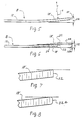
- R is the radius of curvature for switch blade actuator portion 18 as shown in Figure 5 and t is the thickness of switch blade portion 18.
- the amount of bending strain preferably is less than about 8% and most preferably less than about 4%. It will be recognized that this is an approximation for the amount of strain that is in switch blade portion 18.
- the limit on the percent strain is desirable so that the switch will not reclose once it opens.
- the switch blade member can be heat treated and deformed so that it will return to its closed position upon cooling. it is preferred in accordance with the present application to have a switch blade member that remains open even after cooling. Thus, when the switch blade portion moves from a closed position to an open position in response to an elevated temperature condition, it remains open even after the elevated temperature condition no longer exists. If the switch blade portion is deformed beyond the percent strain indicated, it will cause permanent yield of metal beyond the elastic limit which may cause it to return to its closed position upon cooling. Thus, a switch that may reclose upon cooling can be obtained if so desired by initially bending the switch blade actuator to greater than about 8% strain.
- switch blade arm 18 in its deformed martensitic state is indicated at 112 in Figure 5.
- This vertical height is reduced when the switch blade member is sandwiched between metal members C, D.
- vertical height 112 preferably is reduced by at least 15%, more preferably at least 20% and most preferably at least 25%. Although greater reductions in this vertical distance are possible, the maximum preferably is not greater than about 40% or such as to cause yielding of the metal.
- Figure 6 shows switch blade actuator portion 18 under bending stress between surfaces 20, 22 with a reduced vertical height 112a. By way of example. if height 112 is about 45-55 thousandths of an inch. height 112a is about 8-12 thousandths of an inch smaller.
- Figure 7 shows end 32 of switch blade actuator portion 18 as having a relatively sharp edge at the intersection of the upper surface of the blade portion with the blade end. This edge makes substantially line contact with inner surface 22 of metal member C in the switch closed position.
- Figure 8 shows a rounded end 32a that still will make essentially line contact with inner surface 22 of metal member C. Although many other end shapes may be provided, they essentially will make line contact with the inner surface of the metal plate. The line of engagement is between precious metal coatings on both the blade and the inner plate surface.
- the heat that causes the switch to open may be from I 2 R heating, by conduction from the battery case and terminal, by convection from the environment in which the switch is installed, or from a combination of these.
- Reference to a thermal switch encompasses switches that respond to any one or more of these heat sources.
- the current carrying actuator and contact of shape memory metal defined by switch blade actuator portion 18 is in its martensitic deformed shape in the switch closed position.
- the switch blade portion assumes its austenitic recovered shape and moves to a switch open position.
- the switch blade portion does not move back to its closed position so that the switch assembly functions as a one-way fuse. This is achieved principally by controlling the percent strain in the current carrying switchblade actuator in its deformed shape.
- the shape memory metal can be processed so that the switch would reclose upon cooling and the present application covers such arrangements, the most preferred arrangement is one in which the actuator does not fully return to its deformed shape from its recovered shape upon cooling.
- All of the current carrying metal parts of the switch assembly preferably are plated with a precious metal such as silver, gold. platinum or palladium to provide good electrical conductivity.
- the plating is provided on both opposite surfaces and peripheral surfaces of the current currying metal parts C. D and the contact member B.
- the precious metal coating could be applied in ways other than electroplating. such as by vacuum deposition or sputtering. Although it is preferred to coat the entire outer surfaces of the current carrying metal parts with a precious metal, it will be understood that localized coating of small areas may be possible for some applications.
- outer metal parts C, D may be of brass or copper and to minimize corrosion in the event the precious metal coating is nicked, scratched or otherwise broken.
- the switch assembly preferably has a resistivity less than 20 milliohms, more preferably less than about 12 milliohms and most preferably not greater than about 5 or 6 milliohms.
- the extremely low resistivity is achieved by a combination of features that include coating all metal surfaces of current carrying metal parts with a precious metal, assembling the switch under sufficient compression to insure good engagement between the mounting portion of the contact member and the inner surface of a metal plate, and providing a switch blade actuator with sufficient stiffness and placing it in sufficient bending stress to insure good contact between the outer end of the blade and the inner surface of the outer plate.
- normally open switches can be constructed by using features of the present application.
- the switch assembly can be used in other temperature monitoring applications to open a circuit or to close a circuit and sound an alarm.
- a normally open switch arrangement could be used in fire alarms and would move to a switch closed position in response to an elevated temperature to sound an audible signal.
- Contact member B has a diameter of about 0.183 inch and a thickness of about 0.01 inch.
- Switch blade actuator portion 18 has a length of about 0.092 inch.
- Switch blade actuators in accordance with the present application have a length less than about 0.20 inch, preferably less than about 0.15 inch and more preferably not greater than about 0.10 inch.
- the actuator has a thickness less than about 0.02 inch, more preferably less than about 0.15 inch and most preferably not greater than about 0.10 inch.
- the principles of the present application may also be used with dimensions outside of these ranges for some purposes.
- the improved self-contained switch assembly of the present application need not be sealed for use in non-corrosive environments.
- the switch assembly also can be held together in other ways.
- the important features are that the mounting portion of the current carrying shape memory actuator and the dielectric spacer are sandwiched under compression between a pair of outer metal plates. Compression is desirable so that the mounting portion of the current carrying shape memory actuator makes optimum electrical contact with the inner surface of the metal plate with which it is engaged.
- all outer surfaces of current carrying parts of the switch. including peripheral surfaces. are coated with a precious metal.
- the current carrying shape memory actuator has a height in its deformed shape as shown at 112 in Figures 5 and 6 that is substantially greater than the distance between the inner surfaces of the opposite metal plates. This places the actuator under significant bending stress when the switch is assembled so that its end makes good electrical contact with the one plate.
Landscapes
- Chemical & Material Sciences (AREA)
- Chemical Kinetics & Catalysis (AREA)
- Electrochemistry (AREA)
- General Chemical & Material Sciences (AREA)
- Physics & Mathematics (AREA)
- Thermal Sciences (AREA)
- Thermally Actuated Switches (AREA)
- Inorganic Insulating Materials (AREA)
Applications Claiming Priority (4)
| Application Number | Priority Date | Filing Date | Title |
|---|---|---|---|
| US850082 | 1997-05-02 | ||
| US08/850,082 US6069551A (en) | 1997-05-02 | 1997-05-02 | Thermal switch assembly |
| US977077 | 1997-11-24 | ||
| US08/977,077 US6005469A (en) | 1997-05-02 | 1997-11-24 | Thermal switch assembly |
Publications (2)
| Publication Number | Publication Date |
|---|---|
| EP0875913A2 true EP0875913A2 (de) | 1998-11-04 |
| EP0875913A3 EP0875913A3 (de) | 1999-05-06 |
Family
ID=27126898
Family Applications (1)
| Application Number | Title | Priority Date | Filing Date |
|---|---|---|---|
| EP98630014A Withdrawn EP0875913A3 (de) | 1997-05-02 | 1998-04-24 | Temperaturschalteranordnung |
Country Status (4)
| Country | Link |
|---|---|
| US (1) | US6191679B1 (de) |
| EP (1) | EP0875913A3 (de) |
| JP (1) | JPH10321103A (de) |
| CA (1) | CA2233390A1 (de) |
Cited By (6)
| Publication number | Priority date | Publication date | Assignee | Title |
|---|---|---|---|---|
| WO1999010941A1 (en) * | 1997-08-22 | 1999-03-04 | Duracell Inc. | Current interrupter for electrochemical cells |
| EP1005059A1 (de) * | 1998-11-20 | 2000-05-31 | Emerson Electric Co. | Temperaturschalter |
| EP1076350A3 (de) * | 1999-08-11 | 2002-11-06 | Therm-o-Disc Incorporated | Druck- und temperaturempfindlicher Schalter |
| US6570749B1 (en) | 2000-07-14 | 2003-05-27 | Advanced Battery Technology Ltd | Over-current and thermal protection device |
| EP1146579A3 (de) * | 2000-04-12 | 2003-07-16 | Matsushita Electric Industrial Co., Ltd. | Ladbare Batterie mit nichtwässrigem Elektrolyten |
| DE102016209757A1 (de) | 2016-06-03 | 2017-12-21 | Robert Bosch Gmbh | Vorrichtung zur Erhöhung der Sicherheit im Umgang mit einem Batteriesystem |
Families Citing this family (10)
| Publication number | Priority date | Publication date | Assignee | Title |
|---|---|---|---|---|
| US20060263686A1 (en) * | 2005-05-19 | 2006-11-23 | Medtronic, Inc. | Lithium battery manufacturing method |
| US7752866B2 (en) * | 2007-12-07 | 2010-07-13 | University Of Central Florida Research Foundation, Inc. | Shape memory thermal conduction switch |
| KR101349013B1 (ko) * | 2012-04-23 | 2014-01-10 | 현대자동차주식회사 | 형상기억소재를 이용한 전자전기 부품의 하우징 |
| US9627722B1 (en) | 2013-09-16 | 2017-04-18 | American Lithium Energy Corporation | Positive temperature coefficient film, positive temperature coefficient electrode, positive temperature coefficient separator, and battery comprising the same |
| CN115603009A (zh) | 2014-11-25 | 2023-01-13 | 美国锂能源公司(Us) | 配置在可充电电池中的保护层、可充电电池及方法 |
| US10020487B2 (en) | 2014-11-25 | 2018-07-10 | American Lithium Energy Corporation | Rechargeable battery with voltage activated current interrupter |
| US10020545B2 (en) | 2014-11-25 | 2018-07-10 | American Lithium Energy Corporation | Rechargeable battery with resistive layer for enhanced safety |
| CN107946451B (zh) * | 2016-10-12 | 2019-07-12 | 清华大学 | 一种温度感测系统 |
| EP3869600B1 (de) * | 2017-05-01 | 2022-10-19 | American Lithium Energy Corporation | Stromversorgungssystem und sicherung aufweisend eine platte mit negativer wärmeausdehnung |
| US12230844B2 (en) | 2018-06-25 | 2025-02-18 | American Lithium Energy Corporation | Safety layer for battery cells |
Family Cites Families (46)
| Publication number | Priority date | Publication date | Assignee | Title |
|---|---|---|---|---|
| US2497397A (en) | 1946-01-19 | 1950-02-14 | Dales George Franklin | Thermostat switch |
| US2743335A (en) | 1953-09-04 | 1956-04-24 | Gen Motors Corp | Circuit breaker |
| US3033958A (en) * | 1958-07-29 | 1962-05-08 | Alton R Wells | Motor protector or the like |
| US3213250A (en) | 1962-11-30 | 1965-10-19 | Texas Instruments Inc | Miniature snap acting thermostatic switch |
| US3243554A (en) * | 1964-01-23 | 1966-03-29 | Mechanical Products Inc | Combination motor protector and start relay |
| US3430177A (en) * | 1966-12-30 | 1969-02-25 | Texas Instruments Inc | Miniature thermostatic switch |
| US3474372A (en) | 1967-02-16 | 1969-10-21 | Crowell Designs Inc | Temperature-responsive switch having self-contained heater |
| US3707694A (en) | 1970-03-09 | 1972-12-26 | Essex International Inc | Thermally sensitive circuit control apparatus |
| US3801944A (en) | 1972-09-28 | 1974-04-02 | Tri Men Mfg Inc | Temperature-compensated, thermal-activated time delay switch |
| US4035552A (en) * | 1976-07-23 | 1977-07-12 | Gte Laboratories Incorporated | Electrochemical cell |
| US4188460A (en) * | 1978-05-01 | 1980-02-12 | P. R. Mallory & Co., Inc. | Internal battery fuse |
| CH638101A5 (de) * | 1979-05-21 | 1983-09-15 | Cerberus Ag | Brandmelder. |
| DE3027304C2 (de) * | 1980-07-18 | 1982-09-30 | Sds-Elektro Gmbh, 8024 Deisenhofen | Elektrischer Mehrlagenkontakt |
| US4503131A (en) * | 1982-01-18 | 1985-03-05 | Richardson Chemical Company | Electrical contact materials |
| US4395694A (en) | 1982-06-23 | 1983-07-26 | Portage Electric Products, Inc. | Thermostat construction employing aramide insulation |
| JPS59191273A (ja) | 1983-04-14 | 1984-10-30 | Toshiba Battery Co Ltd | 非水溶媒電池 |
| JPS59203376A (ja) | 1983-05-04 | 1984-11-17 | Toshiba Corp | 非水溶媒電池 |
| US4774151A (en) | 1986-05-23 | 1988-09-27 | International Business Machines Corporation | Low contact electrical resistant composition, substrates coated therewith, and process for preparing such |
| US4713643A (en) * | 1986-12-23 | 1987-12-15 | Raychem Corporation | Low loss circuit breaker and actuator mechanism therefor |
| JPS63175345A (ja) | 1987-01-16 | 1988-07-19 | Matsushita Electric Ind Co Ltd | 有機電解液電池 |
| US4782318A (en) | 1987-08-12 | 1988-11-01 | Texas Instruments Incorporated | Thermally responsive electric switch apparatus |
| US4818641A (en) | 1988-04-04 | 1989-04-04 | Eveready Battery Company | Cell circuit interrupter |
| US4855195A (en) | 1988-07-11 | 1989-08-08 | Eveready Battery Company, Inc. | Electrochemical cell with internal circuit interrupter |
| US5061914A (en) * | 1989-06-27 | 1991-10-29 | Tini Alloy Company | Shape-memory alloy micro-actuator |
| US4992339A (en) * | 1990-03-14 | 1991-02-12 | Eveready Battery Company, Inc. | Electrochemical cell with circuit disconnect device |
| US4975341A (en) * | 1990-04-03 | 1990-12-04 | Eveready Battery Company, Inc. | Electrochemical cell with circuit disconnect device |
| US5026615A (en) * | 1990-08-06 | 1991-06-25 | Eveready Battery Company, Inc. | Electrochemical cell with disconnect switch device |
| JPH04345724A (ja) | 1991-05-22 | 1992-12-01 | Fujitsu Ltd | 非破壊ヒューズ |
| US5159307A (en) * | 1991-08-13 | 1992-10-27 | Mighty Mite Controls, Inc. | Electric motor protector |
| US5188909A (en) | 1991-09-12 | 1993-02-23 | Eveready Battery Co., Inc. | Electrochemical cell with circuit disconnect device |
| JP3203623B2 (ja) | 1992-03-06 | 2001-08-27 | ソニー株式会社 | 有機電解液電池 |
| US5206622A (en) | 1992-04-10 | 1993-04-27 | Texas Instruments Incorporated | Protector device with improved bimetal contact assembly and method of making |
| US5268664A (en) | 1993-01-25 | 1993-12-07 | Portage Electric Products, Inc. | Low profile thermostat |
| US5337036A (en) | 1993-07-28 | 1994-08-09 | Kuczynski Robert A | Miniaturized thermal protector with precalibrated automatic resetting bimetallic assembly |
| US5567539A (en) * | 1994-05-23 | 1996-10-22 | Fuji Photo Film Co., Ltd. | Non-aqueous secondary cell |
| JP3261688B2 (ja) | 1994-08-23 | 2002-03-04 | キヤノン株式会社 | 二次電池及びその製造方法 |
| JPH08185849A (ja) | 1994-12-27 | 1996-07-16 | Fuji Elelctrochem Co Ltd | 防爆安全装置を備えた電気化学素子 |
| US5619177A (en) * | 1995-01-27 | 1997-04-08 | Mjb Company | Shape memory alloy microactuator having an electrostatic force and heating means |
| JPH08236102A (ja) | 1995-02-27 | 1996-09-13 | Fuji Elelctrochem Co Ltd | 電気化学素子 |
| EP0739047A3 (de) | 1995-04-21 | 1999-04-07 | Wako Electronics Co., Ltd. | Sicherheitsvorrichtung für einen Akkumulator |
| KR0158845B1 (ko) | 1995-07-28 | 1999-02-18 | 배순훈 | 리튬건전지의 과부하 방지구조 |
| JPH09106804A (ja) | 1995-10-09 | 1997-04-22 | Wako Denshi Kk | 電池の安全装置 |
| US5691073A (en) | 1996-04-10 | 1997-11-25 | Duracell Inc. | Current interrupter for electrochemical cells |
| US5879832A (en) * | 1996-10-02 | 1999-03-09 | Duracell Inc. | Current interrupter for electrochemical cells |
| US5750277A (en) | 1996-04-10 | 1998-05-12 | Texas Instruments Incorporated | Current interrupter for electrochemical cells |
| US5844464A (en) * | 1997-11-24 | 1998-12-01 | Therm-O-Disc, Incorporated | Thermal switch |
-
1998
- 1998-03-26 CA CA002233390A patent/CA2233390A1/en not_active Abandoned
- 1998-04-24 EP EP98630014A patent/EP0875913A3/de not_active Withdrawn
- 1998-05-01 JP JP10137643A patent/JPH10321103A/ja active Pending
- 1998-11-02 US US09/184,199 patent/US6191679B1/en not_active Expired - Fee Related
Cited By (6)
| Publication number | Priority date | Publication date | Assignee | Title |
|---|---|---|---|---|
| WO1999010941A1 (en) * | 1997-08-22 | 1999-03-04 | Duracell Inc. | Current interrupter for electrochemical cells |
| EP1005059A1 (de) * | 1998-11-20 | 2000-05-31 | Emerson Electric Co. | Temperaturschalter |
| EP1076350A3 (de) * | 1999-08-11 | 2002-11-06 | Therm-o-Disc Incorporated | Druck- und temperaturempfindlicher Schalter |
| EP1146579A3 (de) * | 2000-04-12 | 2003-07-16 | Matsushita Electric Industrial Co., Ltd. | Ladbare Batterie mit nichtwässrigem Elektrolyten |
| US6570749B1 (en) | 2000-07-14 | 2003-05-27 | Advanced Battery Technology Ltd | Over-current and thermal protection device |
| DE102016209757A1 (de) | 2016-06-03 | 2017-12-21 | Robert Bosch Gmbh | Vorrichtung zur Erhöhung der Sicherheit im Umgang mit einem Batteriesystem |
Also Published As
| Publication number | Publication date |
|---|---|
| JPH10321103A (ja) | 1998-12-04 |
| CA2233390A1 (en) | 1998-11-02 |
| US6191679B1 (en) | 2001-02-20 |
| EP0875913A3 (de) | 1999-05-06 |
Similar Documents
| Publication | Publication Date | Title |
|---|---|---|
| US6005469A (en) | Thermal switch assembly | |
| US6300858B1 (en) | Thermal switch | |
| US6191679B1 (en) | Thermal switch assembly | |
| US6342826B1 (en) | Pressure and temperature responsive switch assembly | |
| CN1145230C (zh) | 电化学电池的端盖组件和装有端盖组件的电化学电池 | |
| US6210824B1 (en) | Current interrupt apparatus for electrochemical cells | |
| EP0974168B1 (de) | Stromunterbrecher für elektrochemische zellen | |
| US6078244A (en) | Thermal switch | |
| US5998051A (en) | Current interrupter for electrochemical cells | |
| US6570749B1 (en) | Over-current and thermal protection device | |
| EP1029378B1 (de) | Stromunterbrecher für elektrochemische zellen | |
| US6084501A (en) | Thermal cutoff switch | |
| EP0918345A1 (de) | Temperaturschalteranordnung | |
| MXPA98009796A (en) | Term switch | |
| JP2024055191A (ja) | 放電回路 | |
| MXPA00001809A (en) | Current interrupter for electrochemical cells | |
| MXPA00001797A (en) | Current interrupter for electrochemical cells |
Legal Events
| Date | Code | Title | Description |
|---|---|---|---|
| PUAI | Public reference made under article 153(3) epc to a published international application that has entered the european phase |
Free format text: ORIGINAL CODE: 0009012 |
|
| AK | Designated contracting states |
Kind code of ref document: A2 Designated state(s): DE ES FR GB IT |
|
| AX | Request for extension of the european patent |
Free format text: AL;LT;LV;MK;RO;SI |
|
| PUAL | Search report despatched |
Free format text: ORIGINAL CODE: 0009013 |
|
| AK | Designated contracting states |
Kind code of ref document: A3 Designated state(s): AT BE CH CY DE DK ES FI FR GB GR IE IT LI LU MC NL PT SE |
|
| AX | Request for extension of the european patent |
Free format text: AL;LT;LV;MK;RO;SI |
|
| 17P | Request for examination filed |
Effective date: 19991104 |
|
| AKX | Designation fees paid |
Free format text: DE ES FR GB IT |
|
| STAA | Information on the status of an ep patent application or granted ep patent |
Free format text: STATUS: THE APPLICATION IS DEEMED TO BE WITHDRAWN |
|
| 18D | Application deemed to be withdrawn |
Effective date: 20021031 |