EP0875975A1 - Unterputzdose für elektrische Gerät in einer Wand geringer Dicke mit integrierter Spannlasche - Google Patents
Unterputzdose für elektrische Gerät in einer Wand geringer Dicke mit integrierter Spannlasche Download PDFInfo
- Publication number
- EP0875975A1 EP0875975A1 EP98401038A EP98401038A EP0875975A1 EP 0875975 A1 EP0875975 A1 EP 0875975A1 EP 98401038 A EP98401038 A EP 98401038A EP 98401038 A EP98401038 A EP 98401038A EP 0875975 A1 EP0875975 A1 EP 0875975A1
- Authority
- EP
- European Patent Office
- Prior art keywords
- side wall
- clamping
- tab
- box according
- built
- Prior art date
- Legal status (The legal status is an assumption and is not a legal conclusion. Google has not performed a legal analysis and makes no representation as to the accuracy of the status listed.)
- Granted
Links
- 238000009434 installation Methods 0.000 claims description 20
- 238000000465 moulding Methods 0.000 claims description 10
- 229920003023 plastic Polymers 0.000 abstract description 3
- 239000004033 plastic Substances 0.000 abstract description 3
- 230000000712 assembly Effects 0.000 description 9
- 238000000429 assembly Methods 0.000 description 9
- 210000002105 tongue Anatomy 0.000 description 6
- 238000004519 manufacturing process Methods 0.000 description 5
- 239000002184 metal Substances 0.000 description 4
- 238000004806 packaging method and process Methods 0.000 description 3
- 238000005192 partition Methods 0.000 description 3
- 239000011120 plywood Substances 0.000 description 2
- 238000005452 bending Methods 0.000 description 1
- 230000000295 complement effect Effects 0.000 description 1
- 239000002131 composite material Substances 0.000 description 1
- 230000003750 conditioning effect Effects 0.000 description 1
- 229920002994 synthetic fiber Polymers 0.000 description 1
Images


Classifications
-
- H—ELECTRICITY
- H02—GENERATION; CONVERSION OR DISTRIBUTION OF ELECTRIC POWER
- H02G—INSTALLATION OF ELECTRIC CABLES OR LINES, OR OF COMBINED OPTICAL AND ELECTRIC CABLES OR LINES
- H02G3/00—Installations of electric cables or lines or protective tubing therefor in or on buildings, equivalent structures or vehicles
- H02G3/02—Details
- H02G3/08—Distribution boxes; Connection or junction boxes
- H02G3/12—Distribution boxes; Connection or junction boxes for flush mounting
- H02G3/123—Distribution boxes; Connection or junction boxes for flush mounting in thin walls
Definitions
- the present invention relates generally to boxes of the type of those implemented to embed a any apparatus, and, for example, any apparatus electric, in a drywall.
- a drywall is a partition which, dry from prefabricated elements, usually comprises, at the front, a more or less thin facade wall, and the subjection of a box embedded in an opening made for this purpose in this wall of facade is usually done by pinching the latter.
- the mounting boxes have, transversely, projecting outwards, on their side wall, on a at least part of the periphery thereof, a shoulder, which is intended to come wear on the external surface of the front wall to be pinched, and two tabs clamping, which, arranged in diametrically opposite positions with respect to each other to the other, and likely to be brought closer to the previous shoulder under the control of control means, are intended to come to bear on the internal surface of this front wall, for tightening cooperation with this shoulder.
- the means for controlling the clamping lugs are zippers to which these clamping lugs are each individually harnessed, with, intervening between the side wall of the installation box and each of the clamping assemblies that constitute a clamping tab and its zipper, notching means.
- the means notches intervene between the pulls and pawls from the wall side of the installation box.
- the present invention generally relates to a provision to avoid these drawbacks.
- a recessed box of the kind comprising, on the one hand, a side wall, which has, transversely, projecting outwards, over at least part of its periphery, a shoulder, and, on the other hand, at least one clamping tab, which, coupled to a pull tab, is intended to be brought closer to this shoulder for tightening cooperation therewith, intervening between the side wall and the clamping assembly constituted by the clamping tab and its pull tab, notching means, this mounting box being generally characterized in that, coming from a single piece of molding with the wall side, the zipper pull tab initially forms one and the same part with this side wall, while being separable therefrom.
- the zippers then advantageously allow a quick mounting of the installation box in the drywall to be fitted, without any screwing, and while allowing, if necessary, a possible loosening or possible tightening of the front wall of this partition dried.
- the notching means provided between the wall side and each of the clamping assemblies that constitute a lug tightening and its zipper intervene directly, according to the invention, to the right of the clamping tab.
- the wall side has, for this, a slot, which extends over at least part of its height
- the clamping leg belongs to a clamping block, which, at the rear of this clamping tab, has at least one groove allowing it to be engaged on one of the lips of the slot in the side wall
- the means notches have, on the one hand, on the side wall, a series of notches aligned along this lip of its slot, and, on the other hand, on the block of tightening, thanks to the groove thereof, at least one notch capable of cooperating with those on the side wall.
- the following installation box 10 the invention comprises, overall, in a manner known per se, a wall of bottom 11 and a side wall 12.
- the side wall 12 is cylindrical, with generators which extend substantially perpendicular to the bottom wall 11, and, transversely, it has a circular outline.
- the box 10 according to the invention is intended for equipping a drywall 13 having, at the front, a front wall 14 more or less thin, for embedding, in this drywall 13, of any switchgear, and, for example, any non-electrical switchgear represented.
- the mounting box 10 according to the invention has not been shown in all its details in the figures, nor will it be described in full detail here.
- the side wall 12 of the box 10 presents, transversely, projecting outwards, over at least part of its periphery, a shoulder 17, which is intended to limit the engagement of this mounting box 10 in the drywall 13 to be fitted, coming to do this to take support, in the manner a guard, on the front wall 14 thereof, around the opening 15 of this front wall 14.
- this shoulder 17 belongs to a collar 18, which extends overall annularly along the free edge of the side wall 12.
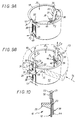
- the invention comprises at least one clamping tab 20, which, coupled to a zipper 21, and thus capable of being moved along the side wall 12, according to modalities described in more detail later, is intended to be close to the shoulder 17, for tightening cooperation therewith, with, acting between the side wall 12 and the clamping assembly 22 that constitute the clamping tab 20 and its zipper 21, notching means 23, Figures 9B and 10.
- the pull tab 21 of the clamping tab 20 of a clamping assembly 22 initially forms a single piece with this side wall 12, while being separable from the latter.
- the zipper 21 of the clamping tab 20 extends initially projecting towards the exterior with respect to the side wall 12.
- this pull tab 21 is then connected to the side wall 12 by a hinge zone 24 adapted to allow it to be folded into the volume interior 25 delimited by the side wall 12.
- the hinge zone 24 intervenes by means of a crosspiece 27, in the form of a handle, that the zipper 21 present at its end opposite to the clamping tab 20, and, as it is better visible in FIG. 6, it comprises two fold lines 28, 29, which, parallel to each other, are spaced from each other, extending one and the other in a plane perpendicular to the generatrices of the side wall 12.
- these fold lines 28, 29 are materialized by grooves recessing the cross member 27, on the lower surface thereof, that is to say on that of the surfaces of this crosspiece 27 which faces the back wall 11.
- the fold line 28 extends to the flush with the side wall 12, while the fold line 29 extends away from this one.
- the zipper 21 of the tab clamp 20 is connected to the side wall 12 along the free edge thereof, and, to do this, the flange 18 of this side wall 12 is locally interrupted, by a notch 30, in line with this zipper 21.
- the cross 27 by which the zipper 21 is connected to the side wall 12 is level with the edge 31, thus released by the notch 30, from this side wall 12.
- the distance D separating the fold lines 28, 29 from each other is at least equal to the thickness E of the side wall 12 measured at the edge 31 of it, figure 6.
- the zipper 21 of the clamping tab 20 is separable from the side wall 12 at its connection to the latter.
- the thickness e1 of the remaining part of the crosspiece 27 at the right of the fold line 28 is less than the thickness e2 of its part remaining at the right of the fold line 29.
- the pull tab 21 of the clamping tab 20 is relatively rigid.
- this zipper 21 is rectilinear, and it takes the form of a thin, flat and smooth strip.
- the pull tab 21 extends initially radially with respect to the side wall 12, parallel to the back wall 11.
- the clamping tab 20 comprises a plate 35 which, like a console, extends in door to false as of zipper 21, perpendicular to it.
- the clamping tab 20 further comprises two dropped edges 36, which extend, each respectively, along the edges of the plate 35, to the stiffening thereof, and which, in the embodiment shown, have a trapezoid configuration, with a large base at the root of the stage 35, i.e. on the side of the pull tab 21, and a small base at the free end of this plate 35, that is to say on the side opposite to the pull tab 21.
- a cross member 37 connects the fallen edges 36 to the other with the root of the plate 35, substantially in continuity with the pull tab 21.
- the notching means 23 intervene directly in the right of the clamping lug 20.
- the side wall 12 comprises, for each of the clamping assemblies 22, a slot 38, which extends over at least part of its height, the clamping tab 20 belongs to a clamping block 39, which, at the rear of this clamping tab 20, that is to say at the root thereof, has at least one groove 40 allowing to be engaged on one of the lips 41 of the slot 38 of the wall lateral 12, and the notching means 23 comprise, on the one hand, on the wall lateral 12, a series of notches 42 aligned along this lip 41 of its slot 38, and, on the other hand, on the clamping block 39, by means of its groove 40, at at least one notch 43 able to cooperate with those, 42, of the side wall 12.
- the clamping block 39 comprises, back to back, two grooves 40, which intervene, each respectively, along the large base of the two fallen edges 36 of the clamping tab 20, along the edge of these fallen edges 36, and by which it can be engaged on the two lips 41 of the slot 38 of the wall lateral 12.
- the notching means 23 comprise notches 42 on each of the lips 41 of the slot 38 of the side wall 12 and at least a notch 43 in each of the grooves 40 of the clamping block 39.
- the clamping block 39 has, on one side of its grooves 40, the clamping tab 20, for cooperation with the shoulder 17 of the side wall 12, on the outer surface thereof, and, on the other side of its grooves 40, a guide counterplate 44, for bearing on the surface inside of the side wall 12.
- this plywood of guide 44 is perforated, in the form of a frame, to allow the molding of all.
- the contour of the clamping tab 20 extends, in plan, entirely within the contour of the internal recess of the guide plate 44, except for two areas of attachment thereto, one which, on the side of the zipper 21, is made by the intermediary of this zipper 21, and the other which, on the side opposite to the zipper 21, is done via a tab 46.
- the edges longitudinal 47 of this guide plate 44 are shaped as dihedral, with their concavity turned towards the clamping lug 20.
- the notches 42 of the wall lateral 12 intervene on the outer surface thereof, and, as it is better visible in FIG. 10, these are asymmetrical notches, these notches 42 with a stiffer side on the upper side, i.e. on the edge side free from the side wall 12, and a less steep sidewall on the lower side, that is to say on the side opposite the previous one.
- the clamping block 39 also includes a series of notches 43 on the edge of each of its dropped edges 36, and they are also asymmetrical notches, these notches 43 being complementary to the notches 42 of the side wall 12.
- the slot 38 in the wall lateral 12 extends over the entire height of this lateral wall 12, according to a generator of it.
- this slot 38 is widened, to allow free passage of the clamping lug 20.
- the slot 38 is, at this level, that is to say on the side opposite the free edge of the side wall 12, at least partly obscured by a foldable tongue 48.
- the width L3 of the slot is less than that L2 of the clamping lug 20.
- the tongue 46 itself has a width at most equal to the latter.
- the slot 38 thereof is closed, in the embodiment shown, by a bar 50, in form of handle, which protrudes slightly from the side wall 12, and which is suitable for providing support for the pull tab 21 of the clamping tab 20.
- the two blocks of clamping 39 each have a protruding lug 51 for their nesting relative when, as shown in Figure 8, the tabs 21 of the tabs clamping 20 are folded into the interior volume 25 delimited by the wall lateral 12.
- the corresponding lugs 51 protrude from the free transverse edge of the guide plywoods 44, and, from one of these guide plates 44 to the other, they are offset one by compared to each other along this one.
- the folding of the zippers 21 and the clamping tabs 20 implies, first, a 180 ° folding of the clamping assemblies 22 correspondents around their fold line 28, which leads the crosspiece 27 of these zippers 21 to be locally superimposed on the edge 31 of the wall lateral 12, and then a bending of less than 90 ° of these clamping assemblies 22 around their fold line 29.
- the zippers 21 of the clamping lugs 20 are separated from the side wall 12, at the fold line 28, and, preferably, the part of their cross 27 extending between this line of fold 28 and the fold line 29 is eliminated.
- the clamping lugs 20 are brought to cross the side wall 12, by means of the part of greater width L1 slots 38 thereof, as shown schematically by arrows F2 in the figure 9A.
- the tongues 48 find, by simple elasticity, their initial position, thus ensuring advantageously at their level the tightness of the installation box 10 with regard to debris of dimensions notable, and more specifically, with regard to debris of which the smallest dimension is greater than 1 mm.
- the hole 33 of the pull tabs 21 can be used to facilitate the exercise of traction on these, by engaging in this hole 33 a any tool, for example the blade of a screwdriver.
- the zippers 21 are then leveled off at the level of the flange 18 of the installation box 10.
Landscapes
- Engineering & Computer Science (AREA)
- Architecture (AREA)
- Civil Engineering (AREA)
- Structural Engineering (AREA)
- Connection Or Junction Boxes (AREA)
- Cartons (AREA)
- Clamps And Clips (AREA)
- Packaging Of Annular Or Rod-Shaped Articles, Wearing Apparel, Cassettes, Or The Like (AREA)
- Packages (AREA)
Applications Claiming Priority (2)
| Application Number | Priority Date | Filing Date | Title |
|---|---|---|---|
| FR9705410A FR2762941B1 (fr) | 1997-04-30 | 1997-04-30 | Boite d'encastrement pour cloison seche a patte(s) de serrage initialement d'un seul tenant, notamment pour appareillage electrique |
| FR9705410 | 1997-04-30 |
Publications (2)
| Publication Number | Publication Date |
|---|---|
| EP0875975A1 true EP0875975A1 (de) | 1998-11-04 |
| EP0875975B1 EP0875975B1 (de) | 2003-07-02 |
Family
ID=9506509
Family Applications (1)
| Application Number | Title | Priority Date | Filing Date |
|---|---|---|---|
| EP98401038A Expired - Lifetime EP0875975B1 (de) | 1997-04-30 | 1998-04-28 | Unterputzdose für elektrische Gerät in einer Wand geringer Dicke mit integrierter Spannlasche |
Country Status (5)
| Country | Link |
|---|---|
| EP (1) | EP0875975B1 (de) |
| AT (1) | ATE244465T1 (de) |
| DE (1) | DE69815941T2 (de) |
| ES (1) | ES2200284T3 (de) |
| FR (1) | FR2762941B1 (de) |
Cited By (3)
| Publication number | Priority date | Publication date | Assignee | Title |
|---|---|---|---|---|
| EP1850435A1 (de) | 2006-04-28 | 2007-10-31 | Abb B.V. | Kasten für elektrische Verdrahtungen mit Positionierungsmitteln |
| EP1768220A3 (de) * | 2005-08-12 | 2010-06-02 | Thorsman & Co. AB | Anschlussdose mit kontinuierlich verstellbaren Montageelementen |
| GB2556022A (en) * | 2016-08-09 | 2018-05-23 | Dsn Innovate Ltd | Electrical socket box |
Families Citing this family (4)
| Publication number | Priority date | Publication date | Assignee | Title |
|---|---|---|---|---|
| FR2923326B1 (fr) | 2007-11-05 | 2010-01-22 | Thierry Fournier | Boitier encastrable dans une cloison |
| ES1110605Y (es) | 2014-05-02 | 2014-08-20 | Rubio Sebastian López | Piezas tubulares y cajas eléctricas encastrables. |
| DE102014226307A1 (de) * | 2014-12-17 | 2016-06-23 | Hager Electro Gmbh & Co. Kg | Befestigungsvorrichtung zur Befestigung eines Installationskastens in einer Wandschalenöffnung |
| FR3104840B1 (fr) * | 2019-12-16 | 2021-11-19 | Legrand France | Support d’appareillage à monter dans une paroi de faible épaisseur et module d’appareillage comportant un tel support |
Citations (3)
| Publication number | Priority date | Publication date | Assignee | Title |
|---|---|---|---|---|
| FR2147029A1 (de) * | 1971-07-26 | 1973-03-09 | Lange & Co | |
| DE3041919A1 (de) * | 1980-11-06 | 1982-06-03 | Günther Spelsberg GmbH & Co KG, 5885 Schalksmühle | Hohlwanddose, wie einbaudose, wandausladose u.dgl., zur aufnahme elektrischer installationsgegenstaende |
| WO1996014682A1 (de) * | 1994-11-04 | 1996-05-17 | Georg Putz | Elektroinstallationsdose für die montage in wänden, insbesondere hohlwänden |
-
1997
- 1997-04-30 FR FR9705410A patent/FR2762941B1/fr not_active Expired - Fee Related
-
1998
- 1998-04-28 EP EP98401038A patent/EP0875975B1/de not_active Expired - Lifetime
- 1998-04-28 DE DE69815941T patent/DE69815941T2/de not_active Expired - Fee Related
- 1998-04-28 ES ES98401038T patent/ES2200284T3/es not_active Expired - Lifetime
- 1998-04-28 AT AT98401038T patent/ATE244465T1/de not_active IP Right Cessation
Patent Citations (3)
| Publication number | Priority date | Publication date | Assignee | Title |
|---|---|---|---|---|
| FR2147029A1 (de) * | 1971-07-26 | 1973-03-09 | Lange & Co | |
| DE3041919A1 (de) * | 1980-11-06 | 1982-06-03 | Günther Spelsberg GmbH & Co KG, 5885 Schalksmühle | Hohlwanddose, wie einbaudose, wandausladose u.dgl., zur aufnahme elektrischer installationsgegenstaende |
| WO1996014682A1 (de) * | 1994-11-04 | 1996-05-17 | Georg Putz | Elektroinstallationsdose für die montage in wänden, insbesondere hohlwänden |
Cited By (4)
| Publication number | Priority date | Publication date | Assignee | Title |
|---|---|---|---|---|
| EP1768220A3 (de) * | 2005-08-12 | 2010-06-02 | Thorsman & Co. AB | Anschlussdose mit kontinuierlich verstellbaren Montageelementen |
| EP1850435A1 (de) | 2006-04-28 | 2007-10-31 | Abb B.V. | Kasten für elektrische Verdrahtungen mit Positionierungsmitteln |
| NL1031723C2 (nl) * | 2006-04-28 | 2007-11-05 | Abb Bv | Doos voor electrische installaties, voorzien van plaatsingsmiddelen. |
| GB2556022A (en) * | 2016-08-09 | 2018-05-23 | Dsn Innovate Ltd | Electrical socket box |
Also Published As
| Publication number | Publication date |
|---|---|
| DE69815941T2 (de) | 2004-05-27 |
| EP0875975B1 (de) | 2003-07-02 |
| FR2762941B1 (fr) | 1999-07-30 |
| ATE244465T1 (de) | 2003-07-15 |
| ES2200284T3 (es) | 2004-03-01 |
| DE69815941D1 (de) | 2003-08-07 |
| FR2762941A1 (fr) | 1998-11-06 |
Similar Documents
| Publication | Publication Date | Title |
|---|---|---|
| EP1094578B1 (de) | Befestigungsklammer für Kabelkanal, insbesondere für elektrische Geräte | |
| EP0075501B1 (de) | Bindestreifen | |
| EP0149377A1 (de) | Verbundkanal mit darauf angebrachtem(en) Element(en) insbesondere für die Aufnahme von elektrischen Kabeln | |
| EP0624940B1 (de) | Rinne mit einer Abdeckungsverbindung mit Verriegelungsvorrichtung, insbesondere für elektrische Geräte | |
| EP0443930A1 (de) | Aus Pappe, Wellpappe oder anderem passend geschnittenem und gefaltetem Folienmaterial hergestellte Verpackung mit einem wiederverschliessbaren, mit einem Handgriff versehenen Deckel und entsprechender Zuschnitt | |
| EP0875975B1 (de) | Unterputzdose für elektrische Gerät in einer Wand geringer Dicke mit integrierter Spannlasche | |
| FR2629893A1 (fr) | Piece de fixation et de raccord pour tubes anneles | |
| FR2780950A1 (fr) | Boite a fermeture inviolable pour le conditionnement de quelconques produits | |
| EP0418152B1 (de) | Modulares, insbesondere elektrisches, Gerät mit Schutzdeckel für Hinweisschilder | |
| EP0114771B1 (de) | Zuschnitt für eine mit einem Handgriff versehene Verpackung, und übereinstimmender Verpackungsentwurf und Verpackung | |
| EP0923176B1 (de) | Greifhalter für Einbaudose und entsprechende Einbaudose | |
| EP2032392A1 (de) | Dichtungsbahn für kraftfahrzeugtür | |
| FR2701007A1 (fr) | Emballage pour appareil auquel il est associé une patère pouvant constituer un capot de protection pour la patère ou l'appareil. | |
| FR2681402A1 (fr) | Profiles d'ossature, notamment pour armoire pour appareillages electriques, et accessoires susceptibles d'etre associes a un tel profile d'ossature. | |
| EP2120651B1 (de) | Als satz lieferbare mailbox | |
| EP1149448B1 (de) | Einbaugerät-befestigungsvorrichtung für kabelkanalsockel | |
| EP0721245B1 (de) | Geräteträger für ein teilweise in einer Leitung versenktes Gehäuse, und Verfahren zu seiner Durchführung | |
| FR2781097A1 (fr) | Boite d'encastrement pour cloison seche a patte(s) de serrage initialement d'un seul tenant, notamment pour appareillage electrique | |
| EP0940349A1 (de) | Dose bestehend aus lösbaren, schwenkbaren Elementen, insbesondere für Leuchten | |
| FR2801734A1 (fr) | Boite a organes de fermeture pour le verrouillage du couvercle sur le corps de boite et a lien de retenue associe a l'un au moins de ces organes de fermeture, notamment pour equipement electrique | |
| EP2099000B1 (de) | Aufbewahrungsgehäuse mit Schnellbefestigung | |
| EP0267079A1 (de) | Abzweigungszubehör für Verkabelungsrohr | |
| FR2773662A1 (fr) | Boitier, en particulier pour bloc autonome d'eclairage de securite | |
| FR2658482A1 (fr) | Emballage en carton, carton ondule ou autre materiau en feuille convenablement decoupe et plie, a couvercle equipe d'une poignee et refermable, et flan(s) correspondant(s). | |
| FR2779123A1 (fr) | Dispositif de liaison, plat, compose de deux pieces pour relier par traction deux parties, notamment deux parties d'une boite |
Legal Events
| Date | Code | Title | Description |
|---|---|---|---|
| PUAI | Public reference made under article 153(3) epc to a published international application that has entered the european phase |
Free format text: ORIGINAL CODE: 0009012 |
|
| AK | Designated contracting states |
Kind code of ref document: A1 Designated state(s): AT BE DE ES GB IT SE |
|
| AX | Request for extension of the european patent |
Free format text: AL;LT;LV;MK;RO;SI |
|
| 17P | Request for examination filed |
Effective date: 19981130 |
|
| AKX | Designation fees paid |
Free format text: AT BE DE ES GB IT SE |
|
| GRAH | Despatch of communication of intention to grant a patent |
Free format text: ORIGINAL CODE: EPIDOS IGRA |
|
| GRAH | Despatch of communication of intention to grant a patent |
Free format text: ORIGINAL CODE: EPIDOS IGRA |
|
| GRAA | (expected) grant |
Free format text: ORIGINAL CODE: 0009210 |
|
| AK | Designated contracting states |
Designated state(s): AT BE DE ES GB IT SE |
|
| REG | Reference to a national code |
Ref country code: GB Ref legal event code: FG4D Free format text: NOT ENGLISH |
|
| REF | Corresponds to: |
Ref document number: 69815941 Country of ref document: DE Date of ref document: 20030807 Kind code of ref document: P |
|
| 111Z | Information provided on other rights and legal means of execution |
Free format text: ATBEDEESGBITSE Effective date: 20030526 |
|
| REG | Reference to a national code |
Ref country code: SE Ref legal event code: TRGR |
|
| GBT | Gb: translation of ep patent filed (gb section 77(6)(a)/1977) |
Effective date: 20031023 |
|
| REG | Reference to a national code |
Ref country code: ES Ref legal event code: FG2A Ref document number: 2200284 Country of ref document: ES Kind code of ref document: T3 |
|
| PLBE | No opposition filed within time limit |
Free format text: ORIGINAL CODE: 0009261 |
|
| STAA | Information on the status of an ep patent application or granted ep patent |
Free format text: STATUS: NO OPPOSITION FILED WITHIN TIME LIMIT |
|
| 26N | No opposition filed |
Effective date: 20040405 |
|
| PGFP | Annual fee paid to national office [announced via postgrant information from national office to epo] |
Ref country code: AT Payment date: 20060316 Year of fee payment: 9 |
|
| PGFP | Annual fee paid to national office [announced via postgrant information from national office to epo] |
Ref country code: GB Payment date: 20060407 Year of fee payment: 9 Ref country code: DE Payment date: 20060407 Year of fee payment: 9 |
|
| PGFP | Annual fee paid to national office [announced via postgrant information from national office to epo] |
Ref country code: ES Payment date: 20060421 Year of fee payment: 9 |
|
| PGFP | Annual fee paid to national office [announced via postgrant information from national office to epo] |
Ref country code: IT Payment date: 20060430 Year of fee payment: 9 |
|
| PGFP | Annual fee paid to national office [announced via postgrant information from national office to epo] |
Ref country code: BE Payment date: 20060504 Year of fee payment: 9 |
|
| GBPC | Gb: european patent ceased through non-payment of renewal fee |
Effective date: 20070428 |
|
| BERE | Be: lapsed |
Owner name: *LEGRAND SNC Effective date: 20070430 Owner name: *LEGRAND FRANCE Effective date: 20070430 |
|
| PG25 | Lapsed in a contracting state [announced via postgrant information from national office to epo] |
Ref country code: DE Free format text: LAPSE BECAUSE OF NON-PAYMENT OF DUE FEES Effective date: 20071101 |
|
| PGFP | Annual fee paid to national office [announced via postgrant information from national office to epo] |
Ref country code: SE Payment date: 20060317 Year of fee payment: 9 |
|
| PG25 | Lapsed in a contracting state [announced via postgrant information from national office to epo] |
Ref country code: AT Free format text: LAPSE BECAUSE OF NON-PAYMENT OF DUE FEES Effective date: 20070428 |
|
| PG25 | Lapsed in a contracting state [announced via postgrant information from national office to epo] |
Ref country code: BE Free format text: LAPSE BECAUSE OF NON-PAYMENT OF DUE FEES Effective date: 20070430 |
|
| PG25 | Lapsed in a contracting state [announced via postgrant information from national office to epo] |
Ref country code: GB Free format text: LAPSE BECAUSE OF NON-PAYMENT OF DUE FEES Effective date: 20070428 |
|
| PG25 | Lapsed in a contracting state [announced via postgrant information from national office to epo] |
Ref country code: SE Free format text: LAPSE BECAUSE OF NON-PAYMENT OF DUE FEES Effective date: 20070429 |
|
| REG | Reference to a national code |
Ref country code: ES Ref legal event code: FD2A Effective date: 20070430 |
|
| PG25 | Lapsed in a contracting state [announced via postgrant information from national office to epo] |
Ref country code: ES Free format text: LAPSE BECAUSE OF NON-PAYMENT OF DUE FEES Effective date: 20070430 |
|
| PG25 | Lapsed in a contracting state [announced via postgrant information from national office to epo] |
Ref country code: IT Free format text: LAPSE BECAUSE OF NON-PAYMENT OF DUE FEES Effective date: 20070428 |