EP0875986A2 - Steuervorrichtung mit Mikroprozessor und Unterspannungsschutz - Google Patents
Steuervorrichtung mit Mikroprozessor und Unterspannungsschutz Download PDFInfo
- Publication number
- EP0875986A2 EP0875986A2 EP98106965A EP98106965A EP0875986A2 EP 0875986 A2 EP0875986 A2 EP 0875986A2 EP 98106965 A EP98106965 A EP 98106965A EP 98106965 A EP98106965 A EP 98106965A EP 0875986 A2 EP0875986 A2 EP 0875986A2
- Authority
- EP
- European Patent Office
- Prior art keywords
- voltage
- microprocessor
- control device
- consumer
- microprocessor control
- Prior art date
- Legal status (The legal status is an assumption and is not a legal conclusion. Google has not performed a legal analysis and makes no representation as to the accuracy of the status listed.)
- Granted
Links
- 230000006978 adaptation Effects 0.000 claims description 2
- 238000012544 monitoring process Methods 0.000 claims description 2
- 238000010438 heat treatment Methods 0.000 claims 1
- 230000008859 change Effects 0.000 description 2
- 238000010586 diagram Methods 0.000 description 2
- 230000000630 rising effect Effects 0.000 description 2
- 230000004913 activation Effects 0.000 description 1
- 230000009286 beneficial effect Effects 0.000 description 1
- 230000009849 deactivation Effects 0.000 description 1
- 238000000034 method Methods 0.000 description 1
- 230000008569 process Effects 0.000 description 1
- 230000004044 response Effects 0.000 description 1
- 230000035945 sensitivity Effects 0.000 description 1
- 238000011144 upstream manufacturing Methods 0.000 description 1
Images

Classifications
-
- H—ELECTRICITY
- H02—GENERATION; CONVERSION OR DISTRIBUTION OF ELECTRIC POWER
- H02H—EMERGENCY PROTECTIVE CIRCUIT ARRANGEMENTS
- H02H3/00—Emergency protective circuit arrangements for automatic disconnection directly responsive to an undesired change from normal electric working condition with or without subsequent reconnection ; integrated protection
- H02H3/24—Emergency protective circuit arrangements for automatic disconnection directly responsive to an undesired change from normal electric working condition with or without subsequent reconnection ; integrated protection responsive to undervoltage or no-voltage
-
- H—ELECTRICITY
- H02—GENERATION; CONVERSION OR DISTRIBUTION OF ELECTRIC POWER
- H02H—EMERGENCY PROTECTIVE CIRCUIT ARRANGEMENTS
- H02H3/00—Emergency protective circuit arrangements for automatic disconnection directly responsive to an undesired change from normal electric working condition with or without subsequent reconnection ; integrated protection
- H02H3/02—Details
- H02H3/06—Details with automatic reconnection
Definitions
- the invention relates to a microprocessor control device with undervoltage protection according to claim 1; such microprocessor control devices are e.g. in modern refrigerators / freezers are used and serve e.g. to Control of a compressor, a heater, a fan or signal indicators.
- Household appliances of the aforementioned type are usually made fed to the household single-phase AC network; there the microprocessor is then connected to a transformer downstream rectifier and voltage regulator if necessary provided.
- the microprocessor switches due to internal Different algorithms or control element specifications Consumers of the aforementioned kind; in terms of such via the microprocessor to the single-phase AC supply network connectable consumers, it must be ensured that that certain loads - such as in the case of a refrigerator / freezer the compressor - because otherwise too big Current consumption not permanent with insufficient primary AC voltage may be operated. It is therefore one Monitoring the primary AC voltage as undervoltage protection to be provided for critical consumers.
- the inventive design of the microprocessor control device is a safe undervoltage protection for against Undervoltage sensitive consumers also guaranteed if to supply the for the control elements of the Consumer provided microprocessor an inexpensive load-sensitive transformer with increasing secondary current not constant, but falling secondary voltage is used.
- a voltage regulator is expediently provided to the microprocessor with which can be activated on the basis of a defined voltage switching threshold Actual value input and with an assigned digital output connected upstream as an interrupt output by signal change (falling / rising or rising / falling) when falling below or exceeding a defined minimum voltage and thus preferably a voltage switching threshold switches off consumers sensitive to undervoltage or switch on again.
- An adaptation of the generally given building-specific Voltage switching threshold to the defined minimum voltage takes place in a particularly simple manner with one of the rectifier devices downstream voltage divider circuit.
- FIG. 1 shows a block diagram of a microprocessor control device according to the invention for four consumers with accordingly four control loads L1-L4 to activate switch-on or switch-off commands of e.g. Relays or triacs, by means of which the consumers are connected to a single-phase AC network with the primary alternating voltage u1.
- This primary alternating voltage u1 is shown in the following also explained in more detail the microprocessor control device 1 fed and monitored.
- An output voltage UG of the rectifier device G becomes as a representative value for the respective secondary AC voltage u2 is used for the undervoltage protection according to the invention and via a voltage divider circuit R1 / R2 with defined Voltage switching threshold US to an actual value input RE1 of the voltage regulator RE or an A / D input of the microprocessor MC given. If the output voltage UG one Has reached the minimum value of the output voltage (e.g. 6 volts), is based on the defined voltage threshold US (e.g.
- FIG 2 first illustrates the load sensitivity of the transformer TR used on the basis of various characteristics of the primary alternating voltage u1 for 100 V, 120 V, 140 V, 160 V, 170 V, 230 V, 265 V in each case as a function of that caused by the control loads L1 -L4 determined load current IL.
- the respective load current IL results from the standby load current of the control device of, for example, 40 mA and a drive load L1 of 60 mA represented, for example, by a drive for a compressor, and a drive load L2 of 20 mA represented by a drive for a light indicator device , a third control load L3 of 10 mA represented by a control for a heater and a fourth control load L4 of 5 mA represented by a control for a fan, so that in the present exemplary embodiment there is a maximum load by a maximum load current IL max of 135 mA results.
- the load current IL increases, the secondary alternating voltage u2 and accordingly the corresponding output voltage UG at the output of the rectifier device G.
- the assumed maximum load current IL max results in a minimum value for the output voltage UG of about 6 V for a corresponding representative value of the output voltage UG of the rectifier device G. Um at this minimum value of the output voltage UG
- the actual value input RE1 of the voltage regulator RE is preceded by a voltage divider circuit R1; R2 such that at a minimum value of the output voltage UG of 6 V a voltage switching threshold US of, for example, 1.25 V is guaranteed in accordance with the component-specific design of the actual value input of the voltage regulator RE.
- a threshold value can be formed by a voltage divider circuit which, at a regularly queried A / D input of the microprocessor MC, leads to the activation or deactivation of the control of a consumer.
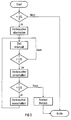
- FIG 3 explains again using a functional sequence Microprocessor control device according to the invention.
- the test sequence can only be activated when an additional one is activated Consumer or in each case after reaching a permissible Undervoltage or even continuously as a measure Test process by briefly switching on another, preferably uncritical consumer.
- the A critical consumer is switched off in each case in the event that the voltage switching threshold in a query function block US and thus the minimum permissible primary AC voltage u1 was undershot or by switching on of a consumer, if this voltage switching threshold US exceeded and thus a sufficient primary AC voltage u1 is reached again.
Landscapes
- Rectifiers (AREA)
- Ac-Ac Conversion (AREA)
Abstract
Description
- FIG 1
- im Blockschaltbild eine erfindungsgemäße Mikroprozessor-Steuervorrichtung;
- FIG 2
- beispielhafte Verläufe der Sekundärwechselspannung des die Mikroprozessor-Steuervorrichtung versorgenden Transformators bei verschiedenen, durch die Ansteuer-Last gegebenen Sekundärstrombelastungen für einen belastungsempfindlichen Transformator;
- FIG 3
- den Funktionsablauf einer erfindungsgemäßen Mikroprozessor-Steuervorrichtung mit Unterspannungsschutz.
Claims (10)
- Mikroprozessor-Steuervorrichtung zum Unterspannungsschutz für aus einem Wechselspannungsnetz gespeiste Verbrauchermit einer Speisung der Steuervorrichtung aus dem Wechselspannungsnetz über einen Transformator (TR);mit einem dem Mikroprozessor (MC) eingangsseitig zugeordneten, mit der Sekundärwechselspannung (u2) des Transformators (TR) gespeisten Gleichrichter-Vorrichtung (G);mit einer Überwachung der Ausgangsspannung (UG) der Gleichrichter-Vorrichtung (G), derart daß bei Unterschreiten einer definierten Mindestspannung zumindest einer der, insbesondere hinsichtlich einer Unterspannungsversorgung empfindlichen, Verbraucher über den Mikroprozessor (MC) abschaltbar bzw. nicht einschaltbar ist;mit einem entsprechend der bei maximal möglicher Ansteuer-Last (L1-L4) durch die Ansteuerung der Verbraucher noch minimal zulässigen Primärwechselspannung (u1) des Wechselspannungsnetzes definierten Mindestwert (UGmin) der Ausgangsspannung (UG) der Gleichrichter-Vorrichtung (G).
- Mikroprozessor-Steuervorrichtung nach dem vorhergehenden Anspruchmit einem bei Erreichen des Mindestwertes (UGmin) der Ausgangsspannung (UG) aufgrund einer entsprechend definierten Spannungs-Schaltschwelle (US) aktivierbaren Mikroprozessor (MC) im Sinne eines abschaltbaren bzw. wiedereinschaltbaren Verbrauchers.
- Mikroprozessor-Steuervorrichtung nach dem vorhergehenden Anspruch 1mit einem dem Mikroprozessor (MC) eingangsseitig zugeordneten Spannungsregler (RE);mit dem Spannungsregler (RE) eingangsseitig zugeordneten, mit der Sekundärwechselspannung (u2) des Transformator (TR) gespeisten Gleichrichter-Vorrichtung (G);mit einem Spannungsregler (RE) mit einem bei Erreichen des Mindestwertes der Ausgangsspannung (UG) aufgrund einer entsprechend definierten Spannungs-Schaltschwelle (US) aktivierbaren Istwerteingang (RE1);mit bei Unterschreiten bzw. Überschreiten der Spannungs-Schaltschwelle (US) über einen Digitalausgang (IRQ) des Spannungsreglers (RE) durch Signalwechsel über den Mikroprozessor (MC) abschaltbarem bzw. wiedereinschaltbarem kritischen Verbraucher.
- Mikroprozessor-Steuervorrichtung nach zumindest einem der vorhergehenden Ansprüche 2 bzw. 3mit einer der Gleichrichter-Vorrichtung (G) nachgeschalteten Spannungsteiler-Schaltung (R1;R2) im Sinne einer festlegbaren Anpassung des Mindestwertes (UGmin) der Ausgangsspannung (UG) der Gleichrichter-Vorrichtung (G) an den Spannungswert der Spannungs-Schaltschwelle (US).
- Mikroprozessor-Steuervorrichtung nach zumindest einem der vorhergehenden Ansprüchemit einem Überprüfen der minimal zulässigen Primärwechselspannung (u1) durch gezieltes Prüf-Zuschalten eines weiterenVerbrauchers, insbesondere eines hinsichtlich einer speisenden Unterspannung unkritischen Verbrauchers.
- Mikroprozessor-Steuervorrichtung nach zumindest einem der vorhergehenden Ansprüchemit einer Verwendung für ein Kühl-/Gefriergerät;mit einer Ansteuer-Last (L1) für einen Verdichter als Verbraucher.
- Mikroprozessor-Steuervorrichtung nach zumindest einem der vorhergehenden Ansprüchemit einer Verwendung für ein Kühl-/Gefriergerät;mit einer Ansteuer-Last (L2) für eine Anzeigevorrichtung als Verbraucher.
- Mikroprozessor-Steuervorrichtung nach zumindest einem der vorhergehenden Ansprüchemit einer Verwendung für ein Kühl-/Gefriergerät;mit einer Ansteuer-Last (L3) für eine Heizung als Verbraucher.
- Mikroprozessor-Steuervorrichtung nach zumindest einem der vorhergehenden Ansprüchemit einer Verwendung für ein Kühl-/Gefriergerät;mit einer Ansteuer-Last (L4) für einen Lüfter als Verbraucher.
- Mikroprozessor-Steuervorrichtung nach zumindest einem der vorhergehenden Ansprüchemit einem lastempfindlichen Transformator (TR), insbesondere einem Transformator (TR) mit bei steigendem Sekundärstrom (i2) fallender Sekundärwechselspannung (u2).
Applications Claiming Priority (2)
| Application Number | Priority Date | Filing Date | Title |
|---|---|---|---|
| DE19718160A DE19718160A1 (de) | 1997-04-29 | 1997-04-29 | Mikroprozessor-Steuervorrichtung mit Unterspannungsschutz |
| DE19718160 | 1997-04-29 |
Publications (3)
| Publication Number | Publication Date |
|---|---|
| EP0875986A2 true EP0875986A2 (de) | 1998-11-04 |
| EP0875986A3 EP0875986A3 (de) | 1999-06-02 |
| EP0875986B1 EP0875986B1 (de) | 2004-03-03 |
Family
ID=7828145
Family Applications (1)
| Application Number | Title | Priority Date | Filing Date |
|---|---|---|---|
| EP98106965A Expired - Lifetime EP0875986B1 (de) | 1997-04-29 | 1998-04-16 | Steuervorrichtung mit Mikroprozessor und Unterspannungsschutz |
Country Status (3)
| Country | Link |
|---|---|
| EP (1) | EP0875986B1 (de) |
| DE (2) | DE19718160A1 (de) |
| ES (1) | ES2221091T3 (de) |
Cited By (3)
| Publication number | Priority date | Publication date | Assignee | Title |
|---|---|---|---|---|
| WO2011066855A1 (en) * | 2009-12-02 | 2011-06-09 | Areva T&D Uk Limited | Method of initiating the load shedding within an electrical power system |
| EP2431830A3 (de) * | 2010-09-21 | 2013-02-20 | Robert Bosch GmbH | Regeleinrichtung für ein wärmetechnisches Gerät |
| CN107272809A (zh) * | 2017-08-14 | 2017-10-20 | 迈普通信技术股份有限公司 | 自动开关电装置及系统 |
Families Citing this family (1)
| Publication number | Priority date | Publication date | Assignee | Title |
|---|---|---|---|---|
| DE102005048016A1 (de) * | 2005-10-07 | 2007-04-12 | Robert Bosch Gmbh | Verfahren und Vorrichtung zur Regelung oder Steuerung eines Aktuators |
Family Cites Families (6)
| Publication number | Priority date | Publication date | Assignee | Title |
|---|---|---|---|---|
| DE3113574A1 (de) * | 1981-04-03 | 1982-10-21 | Linde Ag, 6200 Wiesbaden | Kuehl- oder tiefkuehlmoebel |
| DE3223687A1 (de) * | 1982-06-25 | 1984-01-05 | Licentia Patent-Verwaltungs-Gmbh, 6000 Frankfurt | Stromversorgungseinrichtung fuer ueberstromausloeser mit mikroprozessoren |
| DE3234088A1 (de) * | 1982-09-14 | 1984-04-12 | Karl-Heinz 8025 Unterhaching Schmiegel | Flaechenreinigungsvorrichtung |
| DE3701493A1 (de) * | 1987-01-20 | 1988-07-28 | Nixdorf Computer Ag | Schaltungsanordnung zum verteilen elektrischer speiseleistung auf mehrere funktionseinheiten |
| JP3015388B2 (ja) * | 1989-07-25 | 2000-03-06 | 株式会社東芝 | 電源用モノリシック集積回路 |
| CA2115717A1 (en) * | 1994-02-15 | 1995-08-16 | Nazir Dosani | Method and apparatus for remote control of an electrical load |
-
1997
- 1997-04-29 DE DE19718160A patent/DE19718160A1/de not_active Withdrawn
-
1998
- 1998-04-16 ES ES98106965T patent/ES2221091T3/es not_active Expired - Lifetime
- 1998-04-16 EP EP98106965A patent/EP0875986B1/de not_active Expired - Lifetime
- 1998-04-16 DE DE59810868T patent/DE59810868D1/de not_active Expired - Fee Related
Cited By (4)
| Publication number | Priority date | Publication date | Assignee | Title |
|---|---|---|---|---|
| WO2011066855A1 (en) * | 2009-12-02 | 2011-06-09 | Areva T&D Uk Limited | Method of initiating the load shedding within an electrical power system |
| EP2431830A3 (de) * | 2010-09-21 | 2013-02-20 | Robert Bosch GmbH | Regeleinrichtung für ein wärmetechnisches Gerät |
| CN107272809A (zh) * | 2017-08-14 | 2017-10-20 | 迈普通信技术股份有限公司 | 自动开关电装置及系统 |
| CN107272809B (zh) * | 2017-08-14 | 2019-06-14 | 迈普通信技术股份有限公司 | 自动开关电装置及系统 |
Also Published As
| Publication number | Publication date |
|---|---|
| DE59810868D1 (de) | 2004-04-08 |
| ES2221091T3 (es) | 2004-12-16 |
| DE19718160A1 (de) | 1998-11-05 |
| EP0875986A3 (de) | 1999-06-02 |
| EP0875986B1 (de) | 2004-03-03 |
Similar Documents
| Publication | Publication Date | Title |
|---|---|---|
| US4020358A (en) | Device system and method for controlling the supply of power to an electrical load | |
| DE69333392T2 (de) | Einrichtung zur Bedarfsregelung und Regelsystem zur Energieverteilung | |
| DE69006567T2 (de) | Dampferzeuger für Haushalt und Industrie. | |
| DE3338764A1 (de) | Schaltungsanordnung zum ein- und ausschalten und ueberwachen elektrischer verbraucher | |
| EP0875986B1 (de) | Steuervorrichtung mit Mikroprozessor und Unterspannungsschutz | |
| EP0857369A2 (de) | Vorrichtung zur pufferung der gleichspannung am ausgang einer stromversorgung | |
| DE4019059A1 (de) | Vorrichtung zum ein- und ausschalten einer last | |
| GB2139436A (en) | Mains protection device | |
| EP0588273B1 (de) | Verfahren zum elektronischen Dimmen und Dimmer zur Durchführung des Verfahrens | |
| EP1236257A2 (de) | Überwachungseinheit für stromversorgungen | |
| EP4200623B1 (de) | Vorrichtung und verfahren zur detektion von wechselspannung | |
| DE19807517A1 (de) | 2-Drahtschalter | |
| DE29705504U1 (de) | Mikrocontroller mit überwachter Betriebsspannung | |
| DE9319049U1 (de) | Systemsteuerung zur Reduzierung des Energieverbrauchs von elektronischen Geräten im Standby-Betrieb | |
| EP1090870B1 (de) | Sicherheitskreis für eine Aufzugsanlage | |
| DE3800950A1 (de) | Elektrische schaltung | |
| EP0198222A2 (de) | Lastverteilungsverfahren | |
| DE60306615T2 (de) | Verfahren zur Überwachung eines elektrischen Kontakts | |
| DE935379C (de) | Maximum- und Minimumwaechter fuer elektrische Anlagen | |
| DE2150948A1 (de) | Einrichtung zur begrenzung des einem elektrischen versorgungsnetz entnommenen stromes | |
| EP1154344B1 (de) | Verfahren zur Regelung einer Spannung in einer elektronischen Schaltung und elektronische Schaltung zur Durchführung des Verfahrens | |
| EP0735798B1 (de) | Dämmerungsschalter für Lampen | |
| DE2407245A1 (de) | Anlage zur leistungsbegrenzung bei bezug elektrischer energie von verbrauchern mit mehreren geraeten | |
| DE4010343A1 (de) | Schaltungsanordnung fuer die verbindungsleitung zwischen einer batteriespeicheranlage und einem gleichstromnetz | |
| DE69112283T2 (de) | Elektrisches System mit einem elektromechanischen Relais und einem Gleichrichter-Reduktor-Schaltkreis. |
Legal Events
| Date | Code | Title | Description |
|---|---|---|---|
| PUAI | Public reference made under article 153(3) epc to a published international application that has entered the european phase |
Free format text: ORIGINAL CODE: 0009012 |
|
| AK | Designated contracting states |
Kind code of ref document: A2 Designated state(s): DE ES FR GB IT |
|
| AX | Request for extension of the european patent |
Free format text: AL;LT;LV;MK;RO;SI |
|
| PUAL | Search report despatched |
Free format text: ORIGINAL CODE: 0009013 |
|
| AK | Designated contracting states |
Kind code of ref document: A3 Designated state(s): AT BE CH CY DE DK ES FI FR GB GR IE IT LI LU MC NL PT SE |
|
| AX | Request for extension of the european patent |
Free format text: AL;LT;LV;MK;RO;SI |
|
| RAP1 | Party data changed (applicant data changed or rights of an application transferred) |
Owner name: BSH BOSCH UND SIEMENS HAUSGERAETE GMBH |
|
| 17P | Request for examination filed |
Effective date: 19991126 |
|
| AKX | Designation fees paid |
Free format text: DE ES FR GB IT |
|
| 17Q | First examination report despatched |
Effective date: 20000314 |
|
| GRAP | Despatch of communication of intention to grant a patent |
Free format text: ORIGINAL CODE: EPIDOSNIGR1 |
|
| GRAS | Grant fee paid |
Free format text: ORIGINAL CODE: EPIDOSNIGR3 |
|
| GRAA | (expected) grant |
Free format text: ORIGINAL CODE: 0009210 |
|
| RAP1 | Party data changed (applicant data changed or rights of an application transferred) |
Owner name: BSH BOSCH UND SIEMENS HAUSGERAETE GMBH |
|
| AK | Designated contracting states |
Kind code of ref document: B1 Designated state(s): DE ES FR GB IT |
|
| REG | Reference to a national code |
Ref country code: GB Ref legal event code: FG4D Free format text: NOT ENGLISH |
|
| GBT | Gb: translation of ep patent filed (gb section 77(6)(a)/1977) |
Effective date: 20040303 |
|
| REF | Corresponds to: |
Ref document number: 59810868 Country of ref document: DE Date of ref document: 20040408 Kind code of ref document: P |
|
| ET | Fr: translation filed | ||
| REG | Reference to a national code |
Ref country code: ES Ref legal event code: FG2A Ref document number: 2221091 Country of ref document: ES Kind code of ref document: T3 |
|
| PLBE | No opposition filed within time limit |
Free format text: ORIGINAL CODE: 0009261 |
|
| STAA | Information on the status of an ep patent application or granted ep patent |
Free format text: STATUS: NO OPPOSITION FILED WITHIN TIME LIMIT |
|
| 26N | No opposition filed |
Effective date: 20041206 |
|
| PGFP | Annual fee paid to national office [announced via postgrant information from national office to epo] |
Ref country code: FR Payment date: 20060420 Year of fee payment: 9 |
|
| PGFP | Annual fee paid to national office [announced via postgrant information from national office to epo] |
Ref country code: GB Payment date: 20060426 Year of fee payment: 9 |
|
| PGFP | Annual fee paid to national office [announced via postgrant information from national office to epo] |
Ref country code: ES Payment date: 20060428 Year of fee payment: 9 |
|
| PGFP | Annual fee paid to national office [announced via postgrant information from national office to epo] |
Ref country code: IT Payment date: 20060430 Year of fee payment: 9 Ref country code: DE Payment date: 20060430 Year of fee payment: 9 |
|
| GBPC | Gb: european patent ceased through non-payment of renewal fee |
Effective date: 20070416 |
|
| PG25 | Lapsed in a contracting state [announced via postgrant information from national office to epo] |
Ref country code: DE Free format text: LAPSE BECAUSE OF NON-PAYMENT OF DUE FEES Effective date: 20071101 |
|
| PG25 | Lapsed in a contracting state [announced via postgrant information from national office to epo] |
Ref country code: GB Free format text: LAPSE BECAUSE OF NON-PAYMENT OF DUE FEES Effective date: 20070416 |
|
| REG | Reference to a national code |
Ref country code: ES Ref legal event code: FD2A Effective date: 20070417 |
|
| PG25 | Lapsed in a contracting state [announced via postgrant information from national office to epo] |
Ref country code: FR Free format text: LAPSE BECAUSE OF NON-PAYMENT OF DUE FEES Effective date: 20070430 |
|
| PG25 | Lapsed in a contracting state [announced via postgrant information from national office to epo] |
Ref country code: ES Free format text: LAPSE BECAUSE OF NON-PAYMENT OF DUE FEES Effective date: 20070417 |
|
| PG25 | Lapsed in a contracting state [announced via postgrant information from national office to epo] |
Ref country code: IT Free format text: LAPSE BECAUSE OF NON-PAYMENT OF DUE FEES Effective date: 20070416 |