EP0876002A2 - Pilotsrörungsunterdrückung für einen kohärenten drahtlosen Kodeverteilvielfachzugriffsempfänger - Google Patents
Pilotsrörungsunterdrückung für einen kohärenten drahtlosen Kodeverteilvielfachzugriffsempfänger Download PDFInfo
- Publication number
- EP0876002A2 EP0876002A2 EP98303041A EP98303041A EP0876002A2 EP 0876002 A2 EP0876002 A2 EP 0876002A2 EP 98303041 A EP98303041 A EP 98303041A EP 98303041 A EP98303041 A EP 98303041A EP 0876002 A2 EP0876002 A2 EP 0876002A2
- Authority
- EP
- European Patent Office
- Prior art keywords
- pilot
- signal
- channel
- cdma
- cancellation
- Prior art date
- Legal status (The legal status is an assumption and is not a legal conclusion. Google has not performed a legal analysis and makes no representation as to the accuracy of the status listed.)
- Withdrawn
Links
Images





Classifications
-
- H—ELECTRICITY
- H04—ELECTRIC COMMUNICATION TECHNIQUE
- H04B—TRANSMISSION
- H04B1/00—Details of transmission systems, not covered by a single one of groups H04B3/00 - H04B13/00; Details of transmission systems not characterised by the medium used for transmission
- H04B1/69—Spread spectrum techniques
- H04B1/707—Spread spectrum techniques using direct sequence modulation
- H04B1/7097—Interference-related aspects
- H04B1/7103—Interference-related aspects the interference being multiple access interference
- H04B1/7107—Subtractive interference cancellation
-
- H—ELECTRICITY
- H04—ELECTRIC COMMUNICATION TECHNIQUE
- H04B—TRANSMISSION
- H04B1/00—Details of transmission systems, not covered by a single one of groups H04B3/00 - H04B13/00; Details of transmission systems not characterised by the medium used for transmission
- H04B1/69—Spread spectrum techniques
- H04B1/707—Spread spectrum techniques using direct sequence modulation
- H04B1/7097—Interference-related aspects
- H04B1/7103—Interference-related aspects the interference being multiple access interference
- H04B1/7107—Subtractive interference cancellation
- H04B1/71072—Successive interference cancellation
-
- H—ELECTRICITY
- H04—ELECTRIC COMMUNICATION TECHNIQUE
- H04B—TRANSMISSION
- H04B1/00—Details of transmission systems, not covered by a single one of groups H04B3/00 - H04B13/00; Details of transmission systems not characterised by the medium used for transmission
- H04B1/69—Spread spectrum techniques
- H04B1/707—Spread spectrum techniques using direct sequence modulation
- H04B1/7097—Interference-related aspects
- H04B1/711—Interference-related aspects the interference being multi-path interference
- H04B1/7115—Constructive combining of multi-path signals, i.e. RAKE receivers
-
- H—ELECTRICITY
- H04—ELECTRIC COMMUNICATION TECHNIQUE
- H04B—TRANSMISSION
- H04B1/00—Details of transmission systems, not covered by a single one of groups H04B3/00 - H04B13/00; Details of transmission systems not characterised by the medium used for transmission
- H04B1/69—Spread spectrum techniques
- H04B1/707—Spread spectrum techniques using direct sequence modulation
- H04B1/7097—Interference-related aspects
- H04B1/711—Interference-related aspects the interference being multi-path interference
- H04B1/7115—Constructive combining of multi-path signals, i.e. RAKE receivers
- H04B1/7117—Selection, re-selection, allocation or re-allocation of paths to fingers, e.g. timing offset control of allocated fingers
-
- H—ELECTRICITY
- H04—ELECTRIC COMMUNICATION TECHNIQUE
- H04B—TRANSMISSION
- H04B1/00—Details of transmission systems, not covered by a single one of groups H04B3/00 - H04B13/00; Details of transmission systems not characterised by the medium used for transmission
- H04B1/69—Spread spectrum techniques
- H04B1/707—Spread spectrum techniques using direct sequence modulation
- H04B1/7097—Interference-related aspects
- H04B1/711—Interference-related aspects the interference being multi-path interference
- H04B1/7115—Constructive combining of multi-path signals, i.e. RAKE receivers
- H04B1/712—Weighting of fingers for combining, e.g. amplitude control or phase rotation using an inner loop
-
- H—ELECTRICITY
- H04—ELECTRIC COMMUNICATION TECHNIQUE
- H04B—TRANSMISSION
- H04B1/00—Details of transmission systems, not covered by a single one of groups H04B3/00 - H04B13/00; Details of transmission systems not characterised by the medium used for transmission
- H04B1/69—Spread spectrum techniques
- H04B1/707—Spread spectrum techniques using direct sequence modulation
- H04B1/7097—Interference-related aspects
- H04B1/7103—Interference-related aspects the interference being multiple access interference
- H04B1/7107—Subtractive interference cancellation
- H04B2001/71077—Partial interference cancellation
-
- H—ELECTRICITY
- H04—ELECTRIC COMMUNICATION TECHNIQUE
- H04B—TRANSMISSION
- H04B2201/00—Indexing scheme relating to details of transmission systems not covered by a single group of H04B3/00 - H04B13/00
- H04B2201/69—Orthogonal indexing scheme relating to spread spectrum techniques in general
- H04B2201/707—Orthogonal indexing scheme relating to spread spectrum techniques in general relating to direct sequence modulation
- H04B2201/70701—Orthogonal indexing scheme relating to spread spectrum techniques in general relating to direct sequence modulation featuring pilot assisted reception
-
- H—ELECTRICITY
- H04—ELECTRIC COMMUNICATION TECHNIQUE
- H04B—TRANSMISSION
- H04B2201/00—Indexing scheme relating to details of transmission systems not covered by a single group of H04B3/00 - H04B13/00
- H04B2201/69—Orthogonal indexing scheme relating to spread spectrum techniques in general
- H04B2201/707—Orthogonal indexing scheme relating to spread spectrum techniques in general relating to direct sequence modulation
- H04B2201/70707—Efficiency-related aspects
- H04B2201/70709—Efficiency-related aspects with discontinuous detection
Definitions
- This invention relates to Code Division Multiple Access (CDMA) receivers and, more particularly, to a coherent MC-CDMA receiver using pilot interference cancellation.
- CDMA Code Division Multiple Access
- CDMA Code-Division Multiple Access
- a CDMA receiver which removes the pilot signal from the received signal.
- the pilot signal is defined by its multipath parameters (amplitudes, phase shift and delays) and its signature sequence. Since this information is known at the user's receiver terminal (i.e., handset), the pilot signals of the interfering multipath components of the baseband received signal are detected and removed prior to demodulation of the desired multipath component.
- the CDMA receiver comprises L path demodulators, each demodulator for estimating a data channel and a pilot channel from a CDMA signal received over one of the L paths and for generating L-1 cancellation signals each to be used by a specific one of L subtractor means.
- Each of the L subtractor means is used for subtracting the L-1 cancellation signals, produced by different ones of the other L-1 path demodulators, from the CDMA signal associated with that subtractor means.
- the L-1 cancellation signals are reconstructed pilot signals
- each of the subtractor means is located prior to its associated demodulator to subtract the reconstructed pilot signals from the signal inputted to its demodulator.
- each of the L-1 cancellation signals is a pair of correlator-processed reconstructed pilot signals
- each of the subtractor means is a pair of subtractors, located after a pilot and a data accumulator of its demodulator, for subtracting the pair of correlator-processed reconstructed pilot signals from the signal outputted from its data and pilot accumulators.
- the pilot signal cancellation can be switched on and off in response to a detected path signal level which exceeds a predetermined level.
- Shown in Fig. 1 is a transmitter for a synchronous pilot code aided CDMA communication link, including the values given for IS-95.
- code spreaders 101j and 101k are combined together with a pilot signal in adder 102 to form a Walsh-spread baseband signal.
- the Walsh-spread baseband signal illustratively, at rate R c is multiplied in coders 104-105 by another PN-code spreading sequence, also called short code or pilot code sequence.
- the spreading sequence may be a periodic binary PN-sequence (PN: Pseudo Noise), different for the I- and Q-channel (QPSK-spreading).
- PN Pseudo Noise
- QPSK-spreading QPSK-spreading
- an unmodulated pilot code (Walsh-code 0, always +1, and its data always +1) is embedded in the data signal as a phase reference for coherent demodulation of the data channels at the receiver.
- One pilot channel for all users is sufficient since it is a synchronous CDMA link.
- the outputs from coders 104-105 are each filtered by FIR filters, 106 and 107, respectively.
- the outputs of the FIR filters 106 and 107 are then up-converted by modulators 108 and 109 using radio carrier frequency signals cos( ⁇ c t) and sin( ⁇ c t), respectively.
- the output of modulators 108 and 109 are radio frequency signals which are combined in combiner 110 and transmitted via antenna 111 over the air to the mobile user stations.
- This radio frequency QPSK/CDMA signal includes all channels summed together (data-channels, pilot channel).
- One bit in the baseband (also referred to as symbol) at rate R b consists of g 'chips' at rate R c on the channel.
- Fig. 2 shows a simplified block diagram of an illustrative CDMA receiver that can be used at a mobile station.
- the radio frequency signals received via antenna 201 are down-converted by modulators 202 and 203, using radio frequency signals cos( ⁇ c t) and sin( ⁇ c t), respectively.
- the output of down converters 202 and 203 are each filtered by an anti-aliasing LPF (Low Pass Filter) 204 and 205, respectively to produce a resulting baseband I and Q signals.
- the I and Q signals are then further decoded and despreaded by a CDMA RAKE receiver 208 operating under control of Digital Signal Processor (DSP) 209 to produce the output data signal 210.
- DSP Digital Signal Processor
- a RAKE receiver is an optimum mechanism for receiving signals in a multipath environment when there is no interference due to other users. In our CDMA system, there will be interference due to other users; however, since the cross-correlations between the desired and interfering signals are usually very low, the RAKE receiver provides very good (but not optimum) performance.
- Fig. 3 shows an illustrative block diagram of a prior art RAKE receiver typically used in a CDMA system.
- a RAKE receiver is used in both the forward and reverse links of a CDMA system to take advantage of the inherent time diversity in the received signals arriving via different paths of a multipath environment.
- Analog I signals (I) and Q signals (Q) are converted to digital signals by the A/D circuits 301 and 302, respectively.
- Control logic circuit 303 provides Digital Signal Processor (DSP) interfacing and control, as well as common timing and control functions for the CDMA receiver.
- DSP Digital Signal Processor
- Control logic circuit 303 operates under control of signals received over DSP bus from a DSP, not shown.
- An RSSI (Received Signal Strength Indicator) block 304 calculates the total received signal power of the I and Q signals received over the various signal paths.
- each of the finger units 305-308 is used to demodulate a received signal arriving over a different air path of the multipath environment. These finger units 305-308 are essentially the same except they have a different time delay, attenuation and phase characteristics.
- the finger unit 308 additionally includes a small amount of additional logic to allow its use as a high-speed pilot searcher (for use in coherent receivers to detect the Walsh signal pilot shown in Fig. 1).
- the pilot searcher finger 308 examines the incoming signal by continuously correlating it with the pilot PN-sequence. It detects different base-stations and multipath-components and delivers the respective PN-offsets to the demodulator fingers 305-307.
- Each demodulator finger performs a coherent demodulation of a certain path of the incoming multipath-distorted signal.
- Fig. 4 shows a typical embodiment of a RAKE finger for a coherent CDMA receiver for use in a IS-95 forward link.
- a basic IS-95 RAKE finger in a coherent CDMA receiver has three complex correlators, one for detecting pilot on-time 402, one for detecting pilot early/late 403 and one for data-on-time 404(which together recover the timing signals ).
- This arrangement allows the decoding and despreading of data on a single Walsh channel by data complex correlator 404.
- the data output of correlators 402-404 are then outputted over DSP bus to a DSP unit, not shown.
- the I/Q PN generator 405 provides input codes to the correlators 402-404.
- the Walsh function generator 406 provides a Walsh code to the data correlator 404.
- Control circuit 407 and slew control logic 408 provide control signals for the operation of the RAKE finger and also interface to the DSP bus.
- Fig. 5 we describe the basic demodulator structure of the Pilot-on-time and Data 1 on time complex correlators ( 402 and 404 of Fig. 4, respectively) as a complex signal processing block diagram for a multipath component 0.
- the elements 501-504 provide the Pilot-on-time correlator 402 function while 501-503, 507, 508 provide the Data 1 on time correlator 404 function.
- a complex graphical notation is used in Fig. 5 for simpler schematic drawings and analysis.
- the input signal is (i.e., the I and Q inputs of Fig. 4).
- the on-time selector 501 picks one out of ⁇ samples per chip for further processing.
- pilot despreading is performed. From the resulting signal from multiplier 503, a channel estimate c and ( n ) / ( l ) is obtained from the upper accumulator branch (accumulation over one symbol).
- the upper branch called a 'channel estimation correlator' includes accumulator 504, optionally Channel Estimation Algorithm Block (CAL) 505, and complex conjugate circuit 502. Because the channel coefficients for a particular multipath may not vary much from symbol to symbol, the channel coefficient estimate for the current symbol may be enhanced by CAL 505 which produces a weighted average of all available channel estimates and the current output from 504.
- CAL Channel Estimation Algorithm Block
- Removing the signature code s ( n ) / k ( l ) (Walsh-code for user k ) the lower branch, or 'data correlator' 507-508, recovers the binary information which gets aligned in the signal space (phase/attenuation correction) by multiplying it, in multiplier 509, with the complex conjugate channel estimate ( channel weighting ) from the upper branch.
- the block 510 takes the real part of the complex signal from multiplier 509 (the product of the channel estimate output and data correlator output) and outputs it to the decoding part of the receiver (Viterbi decoder, slicer, or multipath combiner), illustratively shown as a Digital Signal Processor (DSP) 620 of Fig. 6.
- DSP Digital Signal Processor
- the channel estimates c and ( n ) / ( l ) are taken at the symbol-rate. (It is important to mention that the channel estimates include the pilot channel amplitude since they are obtained by correlating with the pilot channel.) It is common to take some sort of weighted sum e.g. a low-pass FIR-filtering - of the last N ⁇ channel estimates (with n as the index of the latest available channel estimate which can be included in the channel estimate calculation algorithm) to get a more reliable channel estimate.
- the gain of the CAL-algorithm is obviously limited by the channel characteristics like fading and VCXO-offset since the channel parameters should remain almost constant during the averaging (or: linear interpolation also possible). If one considers the increasing complexity of CAL it turns out that most of the time a channel estimate over one symbol is sufficient. However, as will be discussed in a later paragraph, our pilot cancellation schemes are not restricted to any channel estimation algorithm.
- the accumulator block it should be noted that it is assumed to have a storage or hold element at its output. It holds the result of the latest accumulation until updating it with a new result each symbol-clock cycle.
- pilot interference cancellation is performed on the chip-samples.
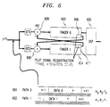
- FIG. 6 we present an overview of our Pilot Interference Cancellation (PIC) schemes.
- PIC Pilot Interference Cancellation
- our receiver example of Fig. 6 receives signals over only two paths 611 and 612 and hence uses only two of the typical three or more fingers of a receiver ( see Fig. 3 ).
- the fingers 603 and 604 operate to demodulate the different path signals 601 and 602,respectively, in the manner previously described.
- the receiver in our example receives a composite signal r (n) and does not know that it includes both the signals from path 0 and path 1.
- the signal of these paths 0 and 1 differ in attenuation ⁇ , phase ⁇ and path delay ⁇ . Since the pilot signals represent about 20 percent of the power of the received path signal, we have recognized that if the the pilot signal of path 1 can be eliminated from the received signal of path 0, and vice-versa, the receiver can make a more accurate demodulation.
- each finger 603 and 604 to additionally include a pilot reconstruction circuit, shown as 606 and 607, respectively, which recover the respective pilot signals from path 0, 611, and path 1, 612.
- the received signal r (n) of path 0, r (0) is first processed by on-time selector circuit (OTS) 601 and then by modified finger 603.
- the received signal r (n) of path 1, r (1) is first processed by on-time selector circuit (OTS) 602 and then by modified finger 604.
- the pilot reconstruction circuits, 606 and 607 recover pilot signals with estimated attenuation ⁇ , phase ⁇ and path delay ⁇ . As shown, the recovered pilot signal from path 0 is subtracted (or cancelled ) in adder circuit 609 from the path 1 signal. In our pre-cancellation schemes, the pilot interference cancellation (subtraction) is performed on the chip-samples prior to demodulation.
- the recovered pilot signal from path 1 is subtracted in adder circuit 608 from the path 0 signal.
- the resulting path 0 and path 1 signals minus the pilot signal of path 1 and path 0, respectively, are then more accurately demodulated in finger 0 and finger 1, respectively.
- the output signals from fingers 0 and 1 are further processed in a bit decision or a Viterbi decoder illustratively implemented in DSP 605.
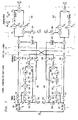
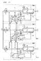
- Fig. 7 there is shown a detailed implementation of a two finger pre-cancellation arrangement using a symbol buffer for obtaining latest channel estimates for pilot cancellation.
- the data has to be buffered. The processing is then done in 3 steps:
- Fig. 7 shows a structure which works according this procedure.
- all of the "primed' numbered blocks operate in the same manner as the non-primed numbered blocks.
- the blocks 501'-505', 509', and 520' operate the same as operate as blocks 501-505, 509, and 520 previously described in Fig. 5.
- the blocks 700 and 700' are separate pilot detectors which use channel estimates (obtained using 504-505 and 504'-505') that have been normalized (by 705 and 705').
- the pulse-shaping for the pilot detectors 700 and 700' is taken into account using RLP blocks 701 and 701' (Reconstruction Low-Pass Filter), respectively.
- the RLPs 701 and 701' are necessary if the delays are not in multiples of the chip-duration. Note, if we did not consider the pulse-shaping the Bit Error Rate (BER) would increase. The implementation of an RLP is described in a later section.
- the symbol buffers 703-704 and 703'-704' enable the symbol data to be buffered while the pilot detectors 701 and 701' are reconstructing the pilot signal.
- delays z -D 702 and 702' compensate for RLP 701 and 701', respectively.
- the influence of an alignment-buffer shown as delays 706-708 and 706'-708' may be considered.
- delays 706-708 and 706'-708' may be considered.
- pilot signal, of path 1 After the pilot signal, of path 0, has been recovered in pilot detector 700, it is applied to the adder 711" to be subtracted from the path 1 signal prior to the demodulation of that signal, by demodulator 520'.
- the non-pulse-shaped (just delayed, see paragraph on RLP) output from RLP block 701 of pilot detector 700 is delayed and conjugated and used as an input to multiplier 503.
- the pilot signal, of path 1 recovered in pilot detector 701' is applied to the adder 711 to be subtracted from the path 0 signal prior to the demodulation of that signal, by demodulator 520.
- the non-pulse-shaped output from RLP block 701' of pilot detector 700' is delayed and conjugated and used as an input to multiplier 503.
- the detector A is modified so that the channel estimate ( obtained in 700 and 700' ), which is used for the pilot reconstruction, is also used for the demodulation process ( by demodulators 520 and 520' ).
- the channel estimate obtained in 700 and 700'
- the demodulation process by demodulators 520 and 520' .
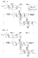
- the timing-chart of Fig. 8 shows how the channel estimates for pilot reconstruction are obtained with respect to the symbol timing.
- the symbol-buffers e.g., 703 guarantees that the pilot cancellation for symbol n can be performed with a channel estimate obtained from data of symbol n (latest channel estimate available).
- the alignment-buffers e.g., 706) guarantees that the new channel estimates for pilot cancellation are available at the beginning of the demodulation process.
- detector A In a Rayleigh-fading environment, the advantage of detector A is that it has the latest channel estimate available for pilot reconstruction which has a positive effect on the BER if the channel characteristics are likely to vary significantly from symbol to symbol.
- the channel estimates for reconstructing the pilot signals are obtained from a signal which did not go through a cancellation stage - to this respect a recursive structure like discussed in the next section will have some advantages since there the channel estimates are taken from data which has already gone through a cancellation stage and therefore is affected by less noise.
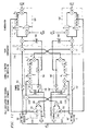
- Fig. 10 Shown in Fig. 10 is a receiver that uses recursive pre-cancellation without working with previous channel estimates. This structure is the most attractive one for implementation, since there is no buffering required. The additional hardware efforts are minimal.
- the channel estimates 1001 and 1001' used for demodulation of the previous symbol n -1, from demodulators 520 ( finger 0) and 520' ( finger 1) are reused, respectively, for reconstructing the pilot signal and cancellation of the next symbol n of fingers 0 and 1, respectively.
- the pilot reconstruction is done in circuits 1010 and 1010'.
- the cancellation is performed in the subtractors 711, 711'.
- the remaining blocks of Detector B operate in the same manner as the identically numbered blocks of previous Figures.
- Fig. 11 Shown in Fig. 11 is a timing-chart for Detector B showing the channel estimates timing for pilot reconstruction. It can be seen that the pilot cancellation for symbol n operates with a channel estimate obtained from data of symbol n -1 (small parts work with estimates of symbol n , n -2).
- the disadvantage of this structure is that the latest channel estimate is not available for cancellation; this can result in performance degradation in a fast fading environment.
- the Fig. 12 shows a combination of the two ideas introduced above: First, using a buffer (i.e., 703 and 703') for having the latest channel estimate available in the CAL for pilot reconstruction ( by 700 and 700' ); and second, a recursive loop (i.e., 1010 and 1010' ) so that even the channel estimation of the pilot reconstruction benefits from a previous pilot cancellation. As shown the recursive loop block 1010' enables ( using adder 1210) a detected pilot signal from path 1 to be subtracted from the signal inputted to the pilot detector 700 of the path 0.
- a buffer i.e., 703 and 703'
- a recursive loop i.e., 1010 and 1010'
- the recursive loop block 1010 enables ( using adder 1210' ) a detected pilot signal from path 0 to be subtracted from the signal inputted to the pilot detector 700' of the path 1.
- the remaining blocks of Detector C operate in the same manner as the identically numbered blocks of previous Figures.
- Timing-chart (not shown, for Detector C which uses the channel estimates for the pilot reconstruction, is similar to that of Detector A except that now there is an additional cancellation that potentially offers better channel estimates for the pilot reconstruction.
- Detector C combines both the latest channel estimate available for pilot reconstruction, and a channel estimate for pilot reconstruction which is obtained from data which benefits from a previous cancellation.
- the performance gain over detector B may not be striking enough to justify the additional hardware complexity (symbol-buffer, a second pilot reconstruction processing with RLP and multiplications at the chip-rate are needed).
- the reconstructed pilot signal gets cancelled out from the received signal r [ i ] ( in adder 1300 ) at the chip-rate prior to demodulation.
- the cancellation stage adders 1301 and 1302
- the accumulators 1303 and 1304
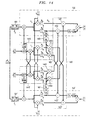
- the Detector D is shown including on-time selectors 501 and 501'; CAL circuits 1401 and 1401'; demodulators 520 and 520'; pilot detectors 1410 and 1410'; and adder circuit 1420.
- the operations of on-time selectors 501 and 501' and demodulators 520 and 520' have previously been described.
- the Detector D uses a reconstructed pilot signal which is accumulated separately (in pilot detectors 1410 and 1410' ) and multiplied ( in multipliers 1402 , 1403 and 1402', 1403' ) by the channel estimate ( from demodulators 520 and 520' and CAL circuits 1401 and 1401' ) at the symbol-rate R b .
- the resulting pilot signals from 1402 and 1402' are then summed in adders 1421 and 1421' to the traffic ( data ) signal of demodulators 520 and 520', respectively.
- the resulting pilot signals from 1403 and 1403' are then summed in adders 1422 and 1422 to the channel estimates of demodulators 520 and 520', respectively.
- a nice side-effect of post-cancellation is that there is no symbol-buffer (e.g., 703 of Fig. 7) necessary anymore (and even no alignment-buffer, e.g., 706) to include the latest channel estimate in the CAL for pilot reconstruction, since the channel estimate multiplication is delayed up to the end of the current symbol.
- symbol-buffer e.g., 703 of Fig. 7
- alignment-buffer e.g., 706
- Detector D is equivalent to detector A, shown in Fig. 7, with alignment-buffer but needs neither a symbol-buffer nor an alignment-buffer.
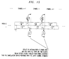
- Fig. 15 Shown in Fig. 15 is a timing diagram for Detector D. As shown, the results of accumulators ,at symbol rate R b , are held until all paths are time-aligned ( delay offsets are usually smaller than symbol durations) and then the cancellation is performed with the latest channel estimates. It should be mentioned that the delay-alignment control (accumulator outputs are held) at the symbol-rate is not explicitly shown in the drawings.
- Detector D The performance of Detector D is similar to that of Detector A.
- the Detector D post-cancellation scheme did not cancel the pilot signal using a channel estimate which itself took advantage of a previous pilot cancellation.
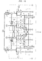
- the structure of Detector E does as is shown in Fig. 16.
- Detector E is shown including on-time selectors 501 and 501'; CAL circuits 1401 and 1401'; demodulators 520 and 520'; pilot detectors 1410 and 1410'; adder circuit 1420; and multipliers 1402,1403 and 1402',1403', the operations of which have previously been described. Additionally, Detector E includes CAL circuits 1601 and 1601' and multipliers 1602 and 1602' which provide a first cancellation stage where only the channel estimate of 1410 and 1410' gets refined. Thereafter, using the better channel estimate the the actual cancellation is performed in adder circuit 1420.
- Detector E The timing diagram of Detector E is the same as that for Detector D,shown in Fig. 15.
- Detector E The performance of Detector E will be close (slightly better) to Detector C, since all channel estimates used for pilot reconstruction or prior to cancellation are the latest ones.
- Fig. 17 Shown in Fig. 17 is an illustrative arrangement of a three finger (3 path ) receiver that uses recursive pre-cancellation without buffer working with previous channel estimates (i.e., Detector B of Fig. 10 ).
- Detector B of Fig. 10 Previous channel estimates
- the RLP now has 2 outputs since the two other fingers, 1 and 2, can have different timing for their on-time samples.
- the reconstruction of pulse-shape of e.g., pilot 0 needs two different fractional delay offsets ⁇ 1 , ⁇ 2 for finger 1, and 2.
- ⁇ 1 , ⁇ 2 for finger 1, and 2.
- fingers 1 and 2 also have the respective pilot signal signals of the other channels cancelled from their input signals.
- the remaining parts of this receiver operates the same as Detector previously described for Detector B of Fig. 10.
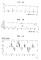
- the Figs. 18-20 illustrate the need of a pulse-shape Reconstruction Low-Pass filter (RLP) when the timing offsets of the multipath components are not in multiples of T c .
- RLP pulse-shape Reconstruction Low-Pass filter
- a part of the sampled pilot signal (e.g. the l-channel) of multipath component 0 is shown.
- normalized Nyquist pulse shape and roll-off factor ⁇ off IS-95: ⁇ off ⁇ 0. );
- i is a sub-chip sample index.
- Shown in Fig. 18 is a short-code sequence, with signal P[i] with sub-chip index.
- Shown in Fig. 19 is a normalized time domain impulse response of a Nyquist-raised cosine filter, up to 4 sidelobes.
- Fig. 20 Shown in Fig. 20 is an example of the pulse-shaped pilot for multipath component 0.
- the above pilot signal may belong to multipath component 0.
- the on-time samples at the chip-rate are (ideally) either +1 or -1 (normalized) since a Nyquist-pulse shaping filter was used in the transmitter (no ISI of neighbor-impulses at the on-time samples).
- the pulse shape matched filter in the receiver also a square-root Nyquist raised filter ] one obtains a Nyquist raised cosine pulse shaping in the baseband of the receiver.
- the FIR-implementation of the reconstruction low-pass filter is fairly simple. We approximate the discrete convolution summation in (*1) by a finite number of N taps (N is an even number).
- Fig 21 Shown in Fig 21 is a FIR-implementation of a Reconstruction Low-Pass filter (RLP).
- the pulse-shaped output at the chip-rate is now with i as a chip-sample index, and p I,Q [ i ] as the short-code sequence.
- pilot interference cancellation should only be performed if the channel estimate used for pilot signal reconstruction is obtained from a multipath component which exceeds a certain power threshold. Otherwise, we may unnecessarily reduce the BER-advantage of pilot cancellation by using bad channel estimates.
- a switch controls whether pilot interference cancellation for a particular pilot signal should or should not occur.
- the decision for this switch is optimum according to a minimum mean-squared error criterion (MMSE), and can be implemented using linear combiners and a threshold device. Hence with a simple decision device, we can determine the optimum set of pilots to cancel and theoretically improve the performance of our pilot interference cancellation system.
- MMSE mean-squared error criterion
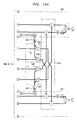
- Figure 22 shows an enhanced PIC detector or receiver of Fig. 6.with the added switch capability(2201, 2202) controlled by Decision unit 2203.
- G and ( n ) / l be the set of pilots which are canceled for the l th finger during symbol interval n. Since pilot I is required to estimate the channel for path l , it cannot be canceled from finger l .
- G and ( n ) / l is a subset of the set ⁇ 0,1, ⁇ , j , ⁇ , L -1; j ⁇ l .
- the Decision unit 2203 determines the cancellation sets G and ( n +1) / 0 and G and ( n +1) / 1 for pilot cancellation on the next symbol interval.
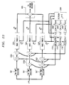
- Fig. 23 is essentially Fig. 17 with the addition of Decision unit 2301 and switches 2202 and 2204. Note that we must reconstruct L - 1 versions of pilot l , each using a separate Reconstruction Low-Pass Filter (RLPF), to match the multipath delay of the finger from which we are canceling the pilot.
- RLPF Reconstruction Low-Pass Filter
- For example, for path 0 we construct the pilot signal for paths 1 and 2(in 1710' and 1710", respectively) which must then be subtracted from the path 0 signal (using adders 2305).
- pilots 0 and 1 are subtracted from the path 2 signals (using 2307) and pilots 0 and 2 are subtracted from path 1 signals (using 2306).
- the above derived switch mechanism for a pilot interference cancellation detector provides minimum mean-squared error rake detector outputs.
Landscapes
- Engineering & Computer Science (AREA)
- Computer Networks & Wireless Communication (AREA)
- Signal Processing (AREA)
- Noise Elimination (AREA)
- Synchronisation In Digital Transmission Systems (AREA)
- Mobile Radio Communication Systems (AREA)
Applications Claiming Priority (2)
| Application Number | Priority Date | Filing Date | Title |
|---|---|---|---|
| US841316 | 1997-04-30 | ||
| US08/841,316 US6067292A (en) | 1996-08-20 | 1997-04-30 | Pilot interference cancellation for a coherent wireless code division multiple access receiver |
Publications (2)
| Publication Number | Publication Date |
|---|---|
| EP0876002A2 true EP0876002A2 (de) | 1998-11-04 |
| EP0876002A3 EP0876002A3 (de) | 2002-02-27 |
Family
ID=25284563
Family Applications (1)
| Application Number | Title | Priority Date | Filing Date |
|---|---|---|---|
| EP98303041A Withdrawn EP0876002A3 (de) | 1997-04-30 | 1998-04-21 | Pilotsrörungsunterdrückung für einen kohärenten drahtlosen Kodeverteilvielfachzugriffsempfänger |
Country Status (4)
| Country | Link |
|---|---|
| US (1) | US6067292A (de) |
| EP (1) | EP0876002A3 (de) |
| JP (1) | JPH10327126A (de) |
| KR (1) | KR100263801B1 (de) |
Cited By (24)
| Publication number | Priority date | Publication date | Assignee | Title |
|---|---|---|---|---|
| GB2337419A (en) * | 1998-04-07 | 1999-11-17 | Nec Corp | Direct sequence CDMA multi-user interference canceller |
| WO2000055992A1 (en) * | 1999-03-17 | 2000-09-21 | Ericsson, Inc. | Synchronization and cell search method and apparatus for wireless communications |
| WO2001001605A1 (en) * | 1999-06-28 | 2001-01-04 | Lucent Technologies Inc. | High-speed data services using multiple transmit antennas |
| WO2001005052A1 (en) * | 1999-07-09 | 2001-01-18 | Nokia Mobile Phones | Interference suppression in a cdma receiver |
| WO2001006670A1 (de) * | 1999-07-15 | 2001-01-25 | Infineon Technologies Ag | Verfahren zur schätzung der kanalimpulsantwort eines mobilfunkkanals |
| WO2001052576A1 (en) * | 2000-01-12 | 2001-07-19 | Mitsubishi Denki Kabushiki Kaisha | Mobile communication terminal |
| EP1143630A1 (de) * | 2000-04-07 | 2001-10-10 | Alcatel | Empfänger für ein CDMA Mobilfunkkommunikationssystem |
| GB2369018A (en) * | 2000-11-10 | 2002-05-15 | Ubinetics Ltd | Control channel interference cancellation for a CDMA receiver |
| WO2002043263A1 (en) * | 2000-11-22 | 2002-05-30 | Koninklijke Philips Electronics N.V. | A rake receiver |
| GB2381715A (en) * | 2001-08-20 | 2003-05-07 | Motorola Inc | a direct sequence spread spectrum (ds-cdma) receiver which uses linear equalization with parallel and iterative interference cancellation |
| EP1191709A4 (de) * | 2000-04-26 | 2003-07-16 | Mitsubishi Electric Corp | Spread-spektrum-empfänger |
| GB2384660A (en) * | 2002-01-25 | 2003-07-30 | Toshiba Res Europ Ltd | CDMA receivers with subtractive suppression of interpath interference (IPI) and multiple access interference (MAI) |
| GB2384664A (en) * | 2002-01-25 | 2003-07-30 | Toshiba Res Europ Ltd | CDMA receivers with subtractive suppression of interpath and multiple access interference (MAI) |
| GB2384661A (en) * | 2002-01-25 | 2003-07-30 | Toshiba Res Europ Ltd | CDMA receivers with subtractive suppression of interpath interference (IPI) and multiple access interference (MAI) |
| GB2384662A (en) * | 2002-01-25 | 2003-07-30 | Toshiba Res Europ Ltd | CDMA receivers with subtractive suppression of interpath interference (IPI) and multiple access interference (MAI) |
| GB2384665A (en) * | 2002-01-25 | 2003-07-30 | Toshiba Res Europ Ltd | CDMA receivers with subtractive suppression of interpath interference (IPI) and multiple access interference (MAI) |
| EP1304815A3 (de) * | 2001-10-17 | 2004-01-02 | The National University of Singapore | Ein Kodeverteilmehrfachzugriff-Abwärtsempfänger |
| WO2004059865A1 (en) * | 2002-12-30 | 2004-07-15 | Koninklijke Philips Electronics N.V. | Training sequence detection scheme and device of downlink in tdd/cdma system |
| EP1318613A3 (de) * | 2001-12-06 | 2004-12-08 | NTT DoCoMo, Inc. | Mobilkommunikationsendgerät, Störungsunterdrückungssystem, Störungsunterdrückungsverfahren und Basisstation |
| EP1605602A1 (de) * | 2004-06-11 | 2005-12-14 | Fujitsu Limited | Interferenzverminderung-Vorrichtung und -Verfahren |
| CN100344073C (zh) * | 2002-08-29 | 2007-10-17 | 美国博通公司 | Cdma系统中自适应消除导频干扰 |
| WO2009158436A1 (en) * | 2008-06-25 | 2009-12-30 | Qualcomm Incorporated | Methods and apparatus for common channel cancellation in wireless communications |
| US7646700B2 (en) | 2000-07-05 | 2010-01-12 | Sony Deutschland Gmbh | Pilot pattern design for an OFDM system |
| EP2922259A4 (de) * | 2012-11-19 | 2016-01-13 | Zte Corp | Verfahren, vorrichtung und basisstation zur interferenzunterdrückung |
Families Citing this family (103)
| Publication number | Priority date | Publication date | Assignee | Title |
|---|---|---|---|---|
| US6678311B2 (en) * | 1996-05-28 | 2004-01-13 | Qualcomm Incorporated | High data CDMA wireless communication system using variable sized channel codes |
| JPH10190521A (ja) * | 1996-12-20 | 1998-07-21 | Fujitsu Ltd | 無線通信装置及び無線通信システム |
| US6173007B1 (en) | 1997-01-15 | 2001-01-09 | Qualcomm Inc. | High-data-rate supplemental channel for CDMA telecommunications system |
| US6628701B2 (en) | 1997-06-11 | 2003-09-30 | Intel Corporation | Method and apparatus for reducing spread spectrum noise |
| US7027490B2 (en) | 1997-06-11 | 2006-04-11 | Intel Corporation | Method and apparatus for reducing spread spectrum noise |
| US6950423B2 (en) * | 1997-09-16 | 2005-09-27 | Ntt Mobile Communications Newtork, Inc. | Packet transmission method, packet transmission device, radio frame transmission method, mobile communication method, mobile communication system, and exchange |
| DE19741872C1 (de) * | 1997-09-23 | 1999-02-04 | Deutsche Telekom Ag | Adaptiver Empfänger für CDMA Basisstationen |
| JPH11154931A (ja) * | 1997-11-19 | 1999-06-08 | Matsushita Electric Ind Co Ltd | レイク受信機とそれを用いた携帯電話の移動機及び基地局 |
| JP3260716B2 (ja) | 1998-06-05 | 2002-02-25 | 松下電器産業株式会社 | 送信装置及びそれを用いた基地局装置 |
| GB2341757B (en) * | 1998-09-21 | 2003-07-02 | Fujitsu Ltd | Code-division multiple access mobile comunications networks |
| US6498784B1 (en) | 1998-10-20 | 2002-12-24 | Interdigital Technology Corporation | Cancellation of pilot and traffic signals |
| EP1011281A3 (de) * | 1998-12-18 | 2000-07-05 | TELEFONAKTIEBOLAGET L M ERICSSON (publ) | Flexibler CDMA Kombinierer |
| JP3363107B2 (ja) | 1999-03-01 | 2003-01-08 | 日本電気株式会社 | 相関値検出装置、それを有するスペクトラム逆拡散装置、受信端末及び送受信端末並びに相関値検出方法 |
| US6711120B1 (en) * | 1999-03-11 | 2004-03-23 | Flarion Technologies, Inc. | Orthogonal frequency division multiplexing based spread spectrum multiple access |
| US7643540B2 (en) | 1999-03-15 | 2010-01-05 | Lg Electronics Inc. | Pilot signals for synchronization and/or channel estimation |
| US6804264B1 (en) | 1999-03-15 | 2004-10-12 | Lg Information & Communications, Ltd. | Pilot signals for synchronization and/or channel estimation |
| US7012906B1 (en) | 1999-03-15 | 2006-03-14 | Lg Information & Communications, Ltd. | Pilot signals for synchronization and/or channel estimation |
| KR100294711B1 (ko) | 1999-03-15 | 2001-07-12 | 서평원 | 최적의 파일럿 심볼을 이용한 프레임 동기 방법 |
| US6721299B1 (en) | 1999-03-15 | 2004-04-13 | Lg Information & Communications, Ltd. | Pilot signals for synchronization and/or channel estimation |
| US6791960B1 (en) | 1999-03-15 | 2004-09-14 | Lg Information And Communications, Ltd. | Pilot signals for synchronization and/or channel estimation |
| US6987746B1 (en) | 1999-03-15 | 2006-01-17 | Lg Information & Communications, Ltd. | Pilot signals for synchronization and/or channel estimation |
| US7496132B2 (en) | 1999-03-15 | 2009-02-24 | Kg Electronics Inc. | Pilot signals for synchronization and/or channel estimation |
| US6891815B1 (en) | 1999-03-15 | 2005-05-10 | Young-Joon Song | Pilot signals for synchronization and/or channel estimation |
| US7130332B1 (en) * | 1999-04-20 | 2006-10-31 | Symmetricom, Inc. | Pilot tracking for synchronization using correlation between digital signal and locally generated version of PN signal |
| US6414988B1 (en) * | 1999-05-12 | 2002-07-02 | Qualcomm Incorporated | Amplitude and phase estimation method in a wireless communication system |
| JP3715141B2 (ja) * | 1999-07-13 | 2005-11-09 | 松下電器産業株式会社 | 通信端末装置 |
| US6404760B1 (en) * | 1999-07-19 | 2002-06-11 | Qualcomm Incorporated | CDMA multiple access interference cancellation using signal estimation |
| EP1073210B1 (de) * | 1999-07-30 | 2007-03-14 | Koninklijke Philips Electronics N.V. | Vorrichtung zur Spreizspektrumdatenübertragung mit einem Datenempfänger |
| US6633552B1 (en) * | 1999-08-06 | 2003-10-14 | Qualcomm Incorporated | Method and apparatus for determining the closed loop power control set point in a wireless packet data communication system |
| US6778507B1 (en) * | 1999-09-01 | 2004-08-17 | Qualcomm Incorporated | Method and apparatus for beamforming in a wireless communication system |
| JP3329379B2 (ja) * | 1999-09-09 | 2002-09-30 | 日本電気株式会社 | 周波数制御方法および受信機 |
| US6798737B1 (en) * | 1999-10-06 | 2004-09-28 | Texas Instruments Incorporated | Use of Walsh-Hadamard transform for forward link multiuser detection in CDMA systems |
| US6760366B1 (en) * | 1999-11-29 | 2004-07-06 | Qualcomm Incorporated | Method and apparatus for pilot search using a matched filter |
| KR100699139B1 (ko) * | 1999-12-31 | 2007-03-21 | 주식회사 케이티 | 블라인드 간섭 제거 방법 |
| CN1171488C (zh) | 2000-01-12 | 2004-10-13 | 三菱电机株式会社 | 移动通信终端及通信方法 |
| US6917642B1 (en) * | 2000-02-23 | 2005-07-12 | Ipr Licensing, Inc. | Method for using a non-orthogonal pilot signal with data channel interference cancellation |
| DE10038314A1 (de) * | 2000-08-05 | 2002-02-14 | Alcatel Sa | Verfahren zum Übertragen von Nutzdatenpaketen |
| US6507604B1 (en) * | 2000-08-31 | 2003-01-14 | Wen-Yi Kuo | Rake receiver for CDMA wireless communications |
| US7443826B1 (en) * | 2000-10-04 | 2008-10-28 | Telefonaktiebolaget L M Ericsson (Publ) | Method and apparatus for automatic frequency control in a CDMA receiver |
| US6680727B2 (en) * | 2000-10-17 | 2004-01-20 | Qualcomm Incorporated | Method and apparatus for canceling pilot interference in a CDMA communication system |
| US6865218B1 (en) | 2000-11-27 | 2005-03-08 | Ericsson Inc. | Multipath interference reduction for a CDMA system |
| JP2002232397A (ja) * | 2001-01-31 | 2002-08-16 | Ntt Docomo Inc | 移動通信システムにおける受信処理方法及び受信装置 |
| US7751469B2 (en) * | 2001-02-20 | 2010-07-06 | Massachusetts Institute Of Technology | Correlation shaping matched filter receiver |
| US7636403B2 (en) * | 2001-02-20 | 2009-12-22 | Massachusetts Institute Of Technology | Correlation shaping multi-signature receiver |
| US7376175B2 (en) * | 2001-03-14 | 2008-05-20 | Mercury Computer Systems, Inc. | Wireless communications systems and methods for cache enabled multiple processor based multiple user detection |
| WO2002073230A2 (en) * | 2001-03-14 | 2002-09-19 | Mercury Computer Systems, Inc. | Wireless communications methods and systems for short-code and other spread spectrum waveform processing |
| US7161927B2 (en) * | 2001-04-18 | 2007-01-09 | Mediatek Inc. | System and method for synchronizing multiuser signals for OFDM CDMA |
| US6853646B2 (en) * | 2001-05-02 | 2005-02-08 | Ipr Licensing, Inc. | Fast switching of forward link in wireless system |
| JP3628977B2 (ja) * | 2001-05-16 | 2005-03-16 | 松下電器産業株式会社 | 無線基地局装置及び通信端末装置 |
| US6996159B2 (en) * | 2001-05-17 | 2006-02-07 | Intel Corporation | Reducing spread spectrum noise |
| US8611311B2 (en) * | 2001-06-06 | 2013-12-17 | Qualcomm Incorporated | Method and apparatus for canceling pilot interference in a wireless communication system |
| US7190749B2 (en) * | 2001-06-06 | 2007-03-13 | Qualcomm Incorporated | Method and apparatus for canceling pilot interference in a wireless communication system |
| US6584141B1 (en) * | 2001-12-21 | 2003-06-24 | Motorola, Inc. | DS-CDMA system with high resolution timing |
| KR100426623B1 (ko) * | 2001-12-22 | 2004-04-13 | 한국전자통신연구원 | 인접 기지국 파일럿 신호 제거를 위한 이동통신 단말기의복조 장치 및 그 방법 |
| US7085582B2 (en) * | 2002-07-31 | 2006-08-01 | Motorola, Inc. | Pilot information gain control method and apparatus |
| KR100459715B1 (ko) * | 2002-08-09 | 2004-12-03 | 삼성전자주식회사 | 고속의 디지털 RSSI(Received Signal Strength Indicator) 회로 |
| WO2004032347A1 (en) * | 2002-08-28 | 2004-04-15 | Agency For Science Technology And Research | Receiver having a signal reconstructing section for noise reduction, system and method thereof |
| US7986742B2 (en) | 2002-10-25 | 2011-07-26 | Qualcomm Incorporated | Pilots for MIMO communication system |
| US7002900B2 (en) | 2002-10-25 | 2006-02-21 | Qualcomm Incorporated | Transmit diversity processing for a multi-antenna communication system |
| US8208364B2 (en) | 2002-10-25 | 2012-06-26 | Qualcomm Incorporated | MIMO system with multiple spatial multiplexing modes |
| US8320301B2 (en) | 2002-10-25 | 2012-11-27 | Qualcomm Incorporated | MIMO WLAN system |
| US20040081131A1 (en) | 2002-10-25 | 2004-04-29 | Walton Jay Rod | OFDM communication system with multiple OFDM symbol sizes |
| US7280467B2 (en) * | 2003-01-07 | 2007-10-09 | Qualcomm Incorporated | Pilot transmission schemes for wireless multi-carrier communication systems |
| CN101610234B (zh) * | 2003-01-07 | 2012-04-25 | 高通股份有限公司 | 无线多载波通信系统的导频传输方法与装置 |
| US7388899B2 (en) * | 2003-03-10 | 2008-06-17 | Texas Instruments Incorporated | Spreading code structure for ultra wide band communications |
| DE10322943B4 (de) * | 2003-05-21 | 2005-10-06 | Infineon Technologies Ag | Hardware-Vorrichtung zur Aufbereitung von Pilotsymbolen für eine Kanalschätzung mittels adaptiver Tiefpassfilterung |
| US7450549B2 (en) * | 2003-08-05 | 2008-11-11 | Via Telecom Co., Ltd. | Pilot signal enhancements for a wireless communication system |
| US7428262B2 (en) * | 2003-08-13 | 2008-09-23 | Motorola, Inc. | Channel estimation in a rake receiver of a CDMA communication system |
| US7391803B2 (en) * | 2003-09-02 | 2008-06-24 | Nokia Corporation | Interference suppression in a receiver during at least one of idle state and access state operation |
| US7058378B2 (en) * | 2003-11-18 | 2006-06-06 | Interdigital Technology Corporation | Method and apparatus for automatic frequency correction of a local oscilator with an error signal derived from an angle value of the conjugate product and sum of block correlator outputs |
| US9473269B2 (en) | 2003-12-01 | 2016-10-18 | Qualcomm Incorporated | Method and apparatus for providing an efficient control channel structure in a wireless communication system |
| US7701917B2 (en) * | 2004-02-05 | 2010-04-20 | Qualcomm Incorporated | Channel estimation for a wireless communication system with multiple parallel data streams |
| CN101027850B (zh) * | 2004-06-30 | 2011-09-28 | 高通股份有限公司 | 无线通信系统中用于消除导频干扰的方法 |
| KR100901669B1 (ko) | 2004-06-30 | 2009-06-08 | 퀄컴 인코포레이티드 | 무선 통신 시스템에서 파일롯 간섭을 소거하는 방법 및장치 |
| US8218694B2 (en) * | 2004-08-03 | 2012-07-10 | Agency For Science, Technology And Research | Method for transmitting a digital signal, method for receiving a digital signal, transmitter and receiver |
| KR100823129B1 (ko) * | 2004-08-18 | 2008-04-21 | 삼성전자주식회사 | 이동통신 시스템의 트랙킹 장치 및 방법 |
| US8442441B2 (en) * | 2004-12-23 | 2013-05-14 | Qualcomm Incorporated | Traffic interference cancellation |
| US8422955B2 (en) * | 2004-12-23 | 2013-04-16 | Qualcomm Incorporated | Channel estimation for interference cancellation |
| US8406695B2 (en) * | 2004-12-23 | 2013-03-26 | Qualcomm Incorporated | Joint interference cancellation of pilot, overhead and traffic channels |
| US8099123B2 (en) * | 2004-12-23 | 2012-01-17 | Qualcomm Incorporated | Adaptation of transmit subchannel gains in a system with interference cancellation |
| US7466749B2 (en) | 2005-05-12 | 2008-12-16 | Qualcomm Incorporated | Rate selection with margin sharing |
| KR100698125B1 (ko) | 2005-06-28 | 2007-03-26 | 엘지전자 주식회사 | 간섭 제거 방법과, 그를 위한 통신단말기 |
| US8594252B2 (en) * | 2005-08-22 | 2013-11-26 | Qualcomm Incorporated | Interference cancellation for wireless communications |
| US9071344B2 (en) | 2005-08-22 | 2015-06-30 | Qualcomm Incorporated | Reverse link interference cancellation |
| US8743909B2 (en) | 2008-02-20 | 2014-06-03 | Qualcomm Incorporated | Frame termination |
| US8611305B2 (en) | 2005-08-22 | 2013-12-17 | Qualcomm Incorporated | Interference cancellation for wireless communications |
| US8472877B2 (en) * | 2005-10-24 | 2013-06-25 | Qualcomm Incorporated | Iterative interference cancellation system and method |
| US8385388B2 (en) * | 2005-12-06 | 2013-02-26 | Qualcomm Incorporated | Method and system for signal reconstruction from spatially and temporally correlated received samples |
| US8045660B1 (en) | 2007-05-23 | 2011-10-25 | Hypres, Inc. | Wideband digital spectrometer |
| KR101514816B1 (ko) * | 2008-06-02 | 2015-04-23 | 삼성전자주식회사 | 알려진 신호를 이용하여 간섭을 인지하는 인지 무선 통신시스템 |
| US9408165B2 (en) | 2008-06-09 | 2016-08-02 | Qualcomm Incorporated | Increasing capacity in wireless communications |
| US20100085913A1 (en) * | 2008-07-02 | 2010-04-08 | Qualcomm Incorporated | System acquisition with interference cancellation in the presence of femtocells |
| US9237515B2 (en) | 2008-08-01 | 2016-01-12 | Qualcomm Incorporated | Successive detection and cancellation for cell pilot detection |
| US9277487B2 (en) | 2008-08-01 | 2016-03-01 | Qualcomm Incorporated | Cell detection with interference cancellation |
| US9160577B2 (en) | 2009-04-30 | 2015-10-13 | Qualcomm Incorporated | Hybrid SAIC receiver |
| US8787509B2 (en) | 2009-06-04 | 2014-07-22 | Qualcomm Incorporated | Iterative interference cancellation receiver |
| US8831149B2 (en) | 2009-09-03 | 2014-09-09 | Qualcomm Incorporated | Symbol estimation methods and apparatuses |
| JP6091895B2 (ja) | 2009-11-27 | 2017-03-08 | クゥアルコム・インコーポレイテッドQualcomm Incorporated | 無線通信における容量の増加 |
| KR101363016B1 (ko) | 2009-11-27 | 2014-02-13 | 퀄컴 인코포레이티드 | 무선 통신들에서의 용량 증가 |
| US8953464B2 (en) | 2010-05-10 | 2015-02-10 | Qualcomm Incorporated | Systems, methods, and computer program products for compensating for interference in sector transmissions |
| EP2541785A1 (de) | 2011-06-29 | 2013-01-02 | TELEFONAKTIEBOLAGET LM ERICSSON (publ) | Verfahren zur Störungsunterdrückung, Funkempfänger, zelluläre Kommunikationsvorrichtung und Computerprogramm |
| US9619227B2 (en) * | 2013-11-15 | 2017-04-11 | Qualcomm Incorporated | Vector processing engines (VPEs) employing tapped-delay line(s) for providing precision correlation / covariance vector processing operations with reduced sample re-fetching and power consumption, and related vector processor systems and methods |
| KR20170019005A (ko) | 2015-08-10 | 2017-02-21 | 정성길 | 높은 풍량을 갖는 부채 |
Family Cites Families (4)
| Publication number | Priority date | Publication date | Assignee | Title |
|---|---|---|---|---|
| US5553062A (en) * | 1993-04-22 | 1996-09-03 | Interdigital Communication Corporation | Spread spectrum CDMA interference canceler system and method |
| US5764687A (en) * | 1995-06-20 | 1998-06-09 | Qualcomm Incorporated | Mobile demodulator architecture for a spread spectrum multiple access communication system |
| ZA965340B (en) * | 1995-06-30 | 1997-01-27 | Interdigital Tech Corp | Code division multiple access (cdma) communication system |
| IL120538A (en) * | 1997-03-26 | 2000-11-21 | Dspc Tech Ltd | Method and apparatus for reducing spread-spectrum noise |
-
1997
- 1997-04-30 US US08/841,316 patent/US6067292A/en not_active Expired - Lifetime
-
1998
- 1998-04-21 EP EP98303041A patent/EP0876002A3/de not_active Withdrawn
- 1998-04-27 JP JP10116412A patent/JPH10327126A/ja active Pending
- 1998-04-30 KR KR1019980015499A patent/KR100263801B1/ko not_active Expired - Fee Related
Cited By (61)
| Publication number | Priority date | Publication date | Assignee | Title |
|---|---|---|---|---|
| GB2337419A (en) * | 1998-04-07 | 1999-11-17 | Nec Corp | Direct sequence CDMA multi-user interference canceller |
| US6600729B1 (en) | 1998-04-07 | 2003-07-29 | Nec Corporation | DS-CDMA multi-user interference canceller and DS-CDMA Communication system |
| GB2337419B (en) * | 1998-04-07 | 2003-03-12 | Nec Corp | DS-CDMA multi-user interference canceller and DS-CDMA communication system |
| US6480558B1 (en) | 1999-03-17 | 2002-11-12 | Ericsson Inc. | Synchronization and cell search methods and apparatus for wireless communications |
| WO2000055992A1 (en) * | 1999-03-17 | 2000-09-21 | Ericsson, Inc. | Synchronization and cell search method and apparatus for wireless communications |
| WO2001001605A1 (en) * | 1999-06-28 | 2001-01-04 | Lucent Technologies Inc. | High-speed data services using multiple transmit antennas |
| WO2001005052A1 (en) * | 1999-07-09 | 2001-01-18 | Nokia Mobile Phones | Interference suppression in a cdma receiver |
| US6570909B1 (en) | 1999-07-09 | 2003-05-27 | Nokia Mobile Phones | Interference suppression in a CDMA receiver |
| WO2001006670A1 (de) * | 1999-07-15 | 2001-01-25 | Infineon Technologies Ag | Verfahren zur schätzung der kanalimpulsantwort eines mobilfunkkanals |
| US6765951B2 (en) | 1999-07-15 | 2004-07-20 | Infineon Technologies Ag | Method for estimating the channel impulse response of a mobile radio channel |
| US7039436B1 (en) | 2000-01-12 | 2006-05-02 | Mitsubishi Denki Kabushiki Kaisha | Mobile communication terminal |
| WO2001052576A1 (en) * | 2000-01-12 | 2001-07-19 | Mitsubishi Denki Kabushiki Kaisha | Mobile communication terminal |
| EP1143630A1 (de) * | 2000-04-07 | 2001-10-10 | Alcatel | Empfänger für ein CDMA Mobilfunkkommunikationssystem |
| CN100448187C (zh) * | 2000-04-07 | 2008-12-31 | 阿尔卡塔尔公司 | 码分多址移动无线通信系统接收器 |
| US6718162B1 (en) | 2000-04-07 | 2004-04-06 | Alcatel | Receiver for a CDMA mobile radiocommunication system |
| US6882681B2 (en) | 2000-04-26 | 2005-04-19 | Mitsubishi Denki Kabushiki Kaisha | Spread spectrum receiving apparatus |
| EP1191709A4 (de) * | 2000-04-26 | 2003-07-16 | Mitsubishi Electric Corp | Spread-spektrum-empfänger |
| US9596113B2 (en) | 2000-07-05 | 2017-03-14 | Sony Deutschland Gmbh | Pilot pattern design for a STTD scheme in an OFDM system |
| US8532133B2 (en) | 2000-07-05 | 2013-09-10 | Sony Deutschland Gmbh | Pilot pattern design for a STTD scheme in an OFDM system |
| US9369323B2 (en) | 2000-07-05 | 2016-06-14 | Sony Deutschland Gmbh | Pilot pattern design for a STTD scheme in an OFDM system |
| US7664009B2 (en) | 2000-07-05 | 2010-02-16 | Sony Deutschland Gmbh | Pilot pattern design for a STTD scheme in an OFDM system |
| US8953632B2 (en) | 2000-07-05 | 2015-02-10 | Sony Deutschland Gmbh | Pilot pattern design for a STTD scheme in an OFDM system |
| US10291454B2 (en) | 2000-07-05 | 2019-05-14 | Wi-Fi One, Llc | Pilot pattern design for a STTD scheme in an OFDM system |
| US8582417B2 (en) | 2000-07-05 | 2013-11-12 | Sony Deutschland Gmbh | Pilot pattern design for a STTD scheme in an OFDM system |
| US7646700B2 (en) | 2000-07-05 | 2010-01-12 | Sony Deutschland Gmbh | Pilot pattern design for an OFDM system |
| US7746759B2 (en) | 2000-07-05 | 2010-06-29 | Sony Deutschland Gmbh | Pilot pattern design for an OFDM system |
| US7660228B2 (en) | 2000-07-05 | 2010-02-09 | Sony Deutschland Gmbh | Pilot pattern design for an OFDM system |
| US8483039B2 (en) | 2000-07-05 | 2013-07-09 | Sony Deutschland Gmbh | Pilot pattern design for a STTD scheme in an OFDM system |
| US9843467B2 (en) | 2000-07-05 | 2017-12-12 | Sony Deutschland Gmbh | Pilot pattern design for a STTD scheme in an OFDM system |
| US7948863B2 (en) | 2000-07-05 | 2011-05-24 | Sony Deutschland Gmbh | Pilot pattern design for a STTD scheme in an OFDM system |
| US7885175B2 (en) | 2000-07-05 | 2011-02-08 | Sony Deutschland Gmbh | Pilot pattern design for an OFDM system |
| GB2369018A (en) * | 2000-11-10 | 2002-05-15 | Ubinetics Ltd | Control channel interference cancellation for a CDMA receiver |
| WO2002043263A1 (en) * | 2000-11-22 | 2002-05-30 | Koninklijke Philips Electronics N.V. | A rake receiver |
| GB2381715B (en) * | 2001-08-20 | 2004-10-20 | Motorola Inc | Linear minimum mean square error equalization with interference cancellation for mobile communication forward links utilizing orthogonal codes covered by long |
| GB2381715A (en) * | 2001-08-20 | 2003-05-07 | Motorola Inc | a direct sequence spread spectrum (ds-cdma) receiver which uses linear equalization with parallel and iterative interference cancellation |
| EP1304815A3 (de) * | 2001-10-17 | 2004-01-02 | The National University of Singapore | Ein Kodeverteilmehrfachzugriff-Abwärtsempfänger |
| EP1318613A3 (de) * | 2001-12-06 | 2004-12-08 | NTT DoCoMo, Inc. | Mobilkommunikationsendgerät, Störungsunterdrückungssystem, Störungsunterdrückungsverfahren und Basisstation |
| US7035590B2 (en) | 2001-12-06 | 2006-04-25 | Ntt Docomo, Inc. | Mobile communication terminal, interference cancellation system, interference cancellation method, and base station |
| GB2384660A (en) * | 2002-01-25 | 2003-07-30 | Toshiba Res Europ Ltd | CDMA receivers with subtractive suppression of interpath interference (IPI) and multiple access interference (MAI) |
| GB2384662B (en) * | 2002-01-25 | 2004-03-24 | Toshiba Res Europ Ltd | Receiver processing systems |
| GB2384664A (en) * | 2002-01-25 | 2003-07-30 | Toshiba Res Europ Ltd | CDMA receivers with subtractive suppression of interpath and multiple access interference (MAI) |
| GB2384661A (en) * | 2002-01-25 | 2003-07-30 | Toshiba Res Europ Ltd | CDMA receivers with subtractive suppression of interpath interference (IPI) and multiple access interference (MAI) |
| GB2384662A (en) * | 2002-01-25 | 2003-07-30 | Toshiba Res Europ Ltd | CDMA receivers with subtractive suppression of interpath interference (IPI) and multiple access interference (MAI) |
| US7295597B2 (en) | 2002-01-25 | 2007-11-13 | Kabushiki Kaisha Toshiba | Receiver processing systems |
| GB2384665A (en) * | 2002-01-25 | 2003-07-30 | Toshiba Res Europ Ltd | CDMA receivers with subtractive suppression of interpath interference (IPI) and multiple access interference (MAI) |
| US7386032B2 (en) | 2002-01-25 | 2008-06-10 | Kabushiki Kaisha Toshiba | Receiver processing systems |
| GB2384661B (en) * | 2002-01-25 | 2005-04-20 | Toshiba Res Europ Ltd | Receiver processing systems |
| GB2384664B (en) * | 2002-01-25 | 2004-12-22 | Toshiba Res Europ Ltd | Receiver processing systems |
| GB2384660B (en) * | 2002-01-25 | 2004-11-17 | Toshiba Res Europ Ltd | Reciever processing systems |
| GB2384665B (en) * | 2002-01-25 | 2004-11-17 | Toshiba Res Europ Ltd | Reciever processing systems |
| CN100344073C (zh) * | 2002-08-29 | 2007-10-17 | 美国博通公司 | Cdma系统中自适应消除导频干扰 |
| WO2004059865A1 (en) * | 2002-12-30 | 2004-07-15 | Koninklijke Philips Electronics N.V. | Training sequence detection scheme and device of downlink in tdd/cdma system |
| EP1605602A1 (de) * | 2004-06-11 | 2005-12-14 | Fujitsu Limited | Interferenzverminderung-Vorrichtung und -Verfahren |
| EP1926219A1 (de) * | 2004-06-11 | 2008-05-28 | Fujitsu Limited | Interferenzreduzierende Vorrichtung und Verfahren |
| US7526012B2 (en) | 2004-06-11 | 2009-04-28 | Fujitsu Limited | Interference reduction apparatus and method |
| CN102077479A (zh) * | 2008-06-25 | 2011-05-25 | 高通股份有限公司 | 用于无线通信中的公共信道消去的方法和装置 |
| US8565775B2 (en) | 2008-06-25 | 2013-10-22 | Qualcomm Incorporated | Methods and apparatus for common channel cancellation in wireless communications |
| CN102077479B (zh) * | 2008-06-25 | 2013-11-20 | 高通股份有限公司 | 用于无线通信中的公共信道消去的方法和装置 |
| WO2009158436A1 (en) * | 2008-06-25 | 2009-12-30 | Qualcomm Incorporated | Methods and apparatus for common channel cancellation in wireless communications |
| EP3399652A1 (de) * | 2008-06-25 | 2018-11-07 | QUALCOMM Incorporated | Verfahren und vorrichtung zur zentralkanalunterdrückung in drahtlosen kommunikationen |
| EP2922259A4 (de) * | 2012-11-19 | 2016-01-13 | Zte Corp | Verfahren, vorrichtung und basisstation zur interferenzunterdrückung |
Also Published As
| Publication number | Publication date |
|---|---|
| KR19980081861A (ko) | 1998-11-25 |
| KR100263801B1 (ko) | 2000-08-16 |
| JPH10327126A (ja) | 1998-12-08 |
| EP0876002A3 (de) | 2002-02-27 |
| US6067292A (en) | 2000-05-23 |
Similar Documents
| Publication | Publication Date | Title |
|---|---|---|
| US6067292A (en) | Pilot interference cancellation for a coherent wireless code division multiple access receiver | |
| US6009089A (en) | Pilot interference cancellation for a coherent wireless code division multiple access receiver | |
| KR101234472B1 (ko) | 무선 통신 시스템에서 파일럿 간섭을 제거하는 방법 및 장치 | |
| CN1143449C (zh) | 扩频瑞克接收机分支内子码片分辨率的样点的合并技术 | |
| EP0641102B1 (de) | Direktsequenz-Kodemultiplexvielfachzugriffsempfänger mit Mehrbenutzerinterferenzkompensator | |
| KR100243720B1 (ko) | 확산 스펙트럼 통신 시스템에서의 복조 및 전력 제어 비트 검출 방법 및 장치 | |
| EP0701344B1 (de) | Adaptiver spreizspektrumempfänger | |
| US5719899A (en) | Multiple access digital transmission system and a radio base station and a receiver for use in such a system | |
| US8611311B2 (en) | Method and apparatus for canceling pilot interference in a wireless communication system | |
| IL142281A (en) | Method and apparatus for interference cancellation in a rake receiver | |
| CA2653507C (en) | Simple and robust digital code tracking loop for wireless communication systems | |
| CA2572090A1 (en) | Method and apparatus for canceling pilot interference in a wireless communication system | |
| EP1176733A1 (de) | Empfänger und empfangsverfahren für spreizspektrumübertragung | |
| EP1289162A2 (de) | Kombination eines Entzerrers mit einem Verfahren zur Interferenzunterdrückung für die Abwärtsrichtung in Spreizspektrumsystemen | |
| Tang et al. | Pilot-channel aided pipeline scheme for interference cancellation in uplink DS/CDMA system | |
| Wijting et al. | An overview of multiuser detection techniques for DS-CDMA in the light of IMT-2000/UMTS | |
| Yu et al. | Hybrid chip-rate equalization of downlink CDMA in SFN channel | |
| Aziz et al. | Industry Articles | |
| WO2005032022A1 (en) | Method and system for multipath interference cancellation for a receiver in a multicode division multiple access system |
Legal Events
| Date | Code | Title | Description |
|---|---|---|---|
| PUAI | Public reference made under article 153(3) epc to a published international application that has entered the european phase |
Free format text: ORIGINAL CODE: 0009012 |
|
| AK | Designated contracting states |
Kind code of ref document: A2 Designated state(s): AT BE CH CY DE DK ES FI FR GB GR IE IT LI LU MC NL PT SE |
|
| AX | Request for extension of the european patent |
Free format text: AL;LT;LV;MK;RO;SI |
|
| PUAL | Search report despatched |
Free format text: ORIGINAL CODE: 0009013 |
|
| AK | Designated contracting states |
Kind code of ref document: A3 Designated state(s): AT BE CH CY DE DK ES FI FR GB GR IE IT LI LU MC NL PT SE |
|
| AX | Request for extension of the european patent |
Free format text: AL;LT;LV;MK;RO;SI |
|
| AKX | Designation fees paid | ||
| REG | Reference to a national code |
Ref country code: DE Ref legal event code: 8566 |
|
| STAA | Information on the status of an ep patent application or granted ep patent |
Free format text: STATUS: THE APPLICATION IS DEEMED TO BE WITHDRAWN |
|
| 18D | Application deemed to be withdrawn |
Effective date: 20021031 |