EP0876671B1 - Appareil de commutation electrique - Google Patents
Appareil de commutation electrique Download PDFInfo
- Publication number
- EP0876671B1 EP0876671B1 EP97914045A EP97914045A EP0876671B1 EP 0876671 B1 EP0876671 B1 EP 0876671B1 EP 97914045 A EP97914045 A EP 97914045A EP 97914045 A EP97914045 A EP 97914045A EP 0876671 B1 EP0876671 B1 EP 0876671B1
- Authority
- EP
- European Patent Office
- Prior art keywords
- contact
- contacts
- moving
- iron core
- drive apparatus
- Prior art date
- Legal status (The legal status is an assumption and is not a legal conclusion. Google has not performed a legal analysis and makes no representation as to the accuracy of the status listed.)
- Expired - Lifetime
Links
- XEEYBQQBJWHFJM-UHFFFAOYSA-N Iron Chemical group [Fe] XEEYBQQBJWHFJM-UHFFFAOYSA-N 0.000 claims description 19
- 230000005540 biological transmission Effects 0.000 claims description 10
- 238000004804 winding Methods 0.000 claims description 5
- 230000009471 action Effects 0.000 claims description 3
- 230000006835 compression Effects 0.000 claims description 2
- 238000007906 compression Methods 0.000 claims description 2
- 210000004243 sweat Anatomy 0.000 description 4
- 230000000694 effects Effects 0.000 description 3
- 238000003466 welding Methods 0.000 description 3
- 230000001419 dependent effect Effects 0.000 description 2
- 230000004048 modification Effects 0.000 description 2
- 238000012986 modification Methods 0.000 description 2
- 210000000056 organ Anatomy 0.000 description 2
- 238000004026 adhesive bonding Methods 0.000 description 1
- 230000003321 amplification Effects 0.000 description 1
- 230000008901 benefit Effects 0.000 description 1
- 230000015572 biosynthetic process Effects 0.000 description 1
- 230000008859 change Effects 0.000 description 1
- 230000008878 coupling Effects 0.000 description 1
- 238000010168 coupling process Methods 0.000 description 1
- 238000005859 coupling reaction Methods 0.000 description 1
- 230000005611 electricity Effects 0.000 description 1
- 238000004146 energy storage Methods 0.000 description 1
- 238000005516 engineering process Methods 0.000 description 1
- 230000003993 interaction Effects 0.000 description 1
- 229910052742 iron Inorganic materials 0.000 description 1
- 230000007246 mechanism Effects 0.000 description 1
- 239000007769 metal material Substances 0.000 description 1
- 238000003199 nucleic acid amplification method Methods 0.000 description 1
- 238000003825 pressing Methods 0.000 description 1
- 238000010791 quenching Methods 0.000 description 1
- 230000000171 quenching effect Effects 0.000 description 1
- 230000009467 reduction Effects 0.000 description 1
- 238000000926 separation method Methods 0.000 description 1
- 238000004904 shortening Methods 0.000 description 1
- 239000007787 solid Substances 0.000 description 1
- 230000001960 triggered effect Effects 0.000 description 1
Images


Classifications
-
- H—ELECTRICITY
- H01—ELECTRIC ELEMENTS
- H01H—ELECTRIC SWITCHES; RELAYS; SELECTORS; EMERGENCY PROTECTIVE DEVICES
- H01H1/00—Contacts
- H01H1/50—Means for increasing contact pressure, preventing vibration of contacts, holding contacts together after engagement, or biasing contacts to the open position
- H01H1/54—Means for increasing contact pressure, preventing vibration of contacts, holding contacts together after engagement, or biasing contacts to the open position by magnetic force
-
- H—ELECTRICITY
- H01—ELECTRIC ELEMENTS
- H01H—ELECTRIC SWITCHES; RELAYS; SELECTORS; EMERGENCY PROTECTIVE DEVICES
- H01H3/00—Mechanisms for operating contacts
- H01H3/001—Means for preventing or breaking contact-welding
-
- H—ELECTRICITY
- H01—ELECTRIC ELEMENTS
- H01H—ELECTRIC SWITCHES; RELAYS; SELECTORS; EMERGENCY PROTECTIVE DEVICES
- H01H50/00—Details of electromagnetic relays
- H01H50/54—Contact arrangements
- H01H50/546—Contact arrangements for contactors having bridging contacts
Definitions
- the invention relates to an electrical switching device with a movable contact element with a pair of movable Contacts, a pair of fixed contact elements, to which the fixed contacts are attached individually, a first electromagnetic drive device with a solid iron core; a movable iron core and one Coil, which is electrically in series with one of the fixed contacts is connected and a second electromagnetic Drive device comprising a yoke, an armature and a winding includes, for switching the load current on and off a transmission link.
- a generic switching device is in the German patent DE 41 04 533 C2 discloses.
- a so-called n-release provided as an auxiliary magnet system, on the armature a plunger is attached to open the contacts serves when overcurrents occur.
- This is supposed to be a weld of contacts prevented as a result of overcurrents are, when they occur, the contacts are dependent on current Formation of arcs are more or less separated.
- the Tappet is tubular in the cylindrical cavity Contact bridge carrier, which is operated via a lever by a main magnet system for switching the Load current is actuated.
- the auxiliary magnet system so below the contact arrangement that the axial line of the plunger with the longitudinal central axis of the contact bridge carrier flees.
- the main magnet system is next to that Auxiliary magnet system, i.e. to the longitudinal central axis of the contact bridge support laterally offset.
- DE-OS 28 48 287 discloses a magnetic switch in which the contacts for switching the load circuit on and off can be opened quickly if overcurrents occur.
- the Magnetic switch is an overcurrent sensitive device with a winding through which the load current flows and a magnetic core, which is provided with a striker.
- An electromagnet switches the load current on and off via the contacts, why its anchor via a magnetic energy storage with a longitudinally movable transmission element is coupled, that is a movement in the longitudinal direction when the electromagnet is excited executes while doing that on a movable contact bridge fixed movable contacts of fixed contacts takes off.
- the armature of the Magnetic switch in such a way on the spring force accumulator that this the transmission organ suddenly accelerated and the contacts tears open to avoid welding.
- the power transmission the electromagnet can also be connected to a push rod take place in a operated by the magnetic switch Transmission organ is guided.
- the invention is based, the switchgear the task to improve the above-mentioned type in such a way that a weld of contacts by avoiding overcurrent dependent Arc is excluded.
- the object is achieved in that the Transmission link as a contact bridge support with a window is carried out in which the movable contact element is added is that the contact bridge support without intermediate connection of levers coupled to the anchor that the movable Iron core of the first drive device on the contact bridge carrier is attached and that on the movable Iron core acts a force proportional to the load current that holds the contacts closed via the contact bridge carrier.
- first and second drive devices coaxial with each other are arranged and have a common line of force action, with the axis of symmetry of the contact bridge support flees.
- This has the advantage that only longitudinal forces take effect and the forces to develop fully without loss can be brought, i.e. e.g. Friction losses, such as they usually occur when using reversing levers, be avoided.
- the contact bridge support comprises two parts that are relative can move towards each other in one direction this is that the contact bridge support when closed Magnetic circuit of the second drive device due to Shorten the force of the first drive device in this way can that the pressure of the movable contacts on the fixed Contacts is increased.
- the parts of the contact carrier are advantageously a Anchor of the second drive device attached contact carrier plate and one coupled to it via a springêttragerdom. The shortening of the This makes contact bridge support easy reached.
- the Contact carrier dome is provided with the window in which the movable contact element by a contact spring in the direction the fixed contacts are biased and if a pressure piece is provided, which the travel by which the spring at Compression can be shortened.
- This version has as a result, the additional force of the first drive device if overcurrents occur directly via the contact carrier dome and the pressure piece for pressing the movable contacts on the fixed contacts. In this case therefore no longer the force effect of the contact spring is decisive as when switching on by the first drive device.
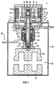
- FIG. 1 shows an electrical switching device 1 according to a first Embodiment with a contact device 3,4,5 in one Arc chamber 2, one of the contact devices 3,4,5 actuating Main magnet system 16, and one between the contact device 3,4,5 and the main magnet system 16 arranged Auxiliary magnet system 22,23,24.
- the main magnet system 16 and the auxiliary magnet system 22,23,24 are as electromagnetic Drive devices trained.
- the auxiliary magnet system 22,23,24 is advantageously in the line of action of the Main magnet system 16 arranged so that both are in contrast to the previous technology, which works with reversing levers, without delay their effect without the interposition of reversing levers unfold.
- the absence of bellcranks also means a reduction in components, which is usually the goal becomes.
- the contact device 3, 4, 5 comprises a movable contact bridge 3 as a movable contact element with one each movable contact 4 at opposite end regions the contact bridge 3.
- the movable contacts 4 are a pair of fixed contacts 5 arranged opposite.
- the fixed contacts 5 are each with a contact element 6 connected to a housing paragraph 7 inside an upper housing half 8 is attached.
- the contact bridge 3 is in a window 9 of a rod-shaped, two-part contact bridge carrier inserted, which essentially consists of a contact carrier dome 10 and one Contact carrier plate 11 is made.
- the contact carrier dome 10 is 1 above via a coil spring 12 as the main contact spring held, the contact carrier dome 10 and the contact bridge 3 in a guide 13 in FIG 1 by the coil spring 12 after are biased below.
- a pair of arranged in groups Arc quenching plates 14 made of a magnetic, metallic Material are on opposite sides the contact bridge 3 is provided to extinguish the arcs, which is the contact separation between the moving contacts 4 and the fixed contacts 5 are pulled.
- the auxiliary magnet system comprises a fixed iron core which is formed by two U-shaped iron sheets 22, a coil 23 and an anchor 24 as a movable iron core.
- the main magnet system serving as the operating and operating mechanism 16 lies in a lower housing half according to FIG 15. It is designed as an electromagnet, which in essentially a fixed iron core 17, a movable Armature 18 and a coil or winding, not shown here includes that for actuating the switching device via a Control circuit can be supplied with electricity.
- FIGS. 1 and 2 shows the switching device 1 according to the invention when switched on Condition, i.e. with current supply.
- the function of the Switching device 1 is described below with reference to FIGS. 1 and 2 explained.
- the main magnet system 16 If the main magnet system 16 is controlled, it moves Anchor 18 in the figure representation down and takes the Position according to FIG 2. With this downward movement the Contact bridge carrier 10.11 due to the coupling downwards carried along, the contact spring 12 after support of the movable Contacts 4 on the fixed contacts 5 almost around Travel is compressed, the air gap 27 in the de-energized State of the switching device 1 according to FIG 2 corresponds.
- FIG. 3 shows a switching device 1 according to a second embodiment shown in the switched on state. This largely agrees with the first embodiment of the switching device 1 according to FIGS. 1 and 2. In this respect, one Description of the matching components waived and these are given the same reference numerals as in FIGS. 1 and 2 Mistake.
- the main modification in the second embodiment concerns the structure of the contact bridge carrier. This exists here also from a contact carrier plate 11 and a tubular contact support dome 10 with a window 9 for receiving the contact spring 12. However, there is no pressure piece and the contact carrier dome 10 and the contact carrier plate 11 are firmly connected, e.g. through a screw connection, by gluing or welding.
- the cavity 24 of the contact carrier dome 10 is the armature 24 of the auxiliary magnet system movably mounted and at its upper Provide the end with a plunger 29 or striker that when triggered by an over or short circuit current in the Window 9 can be moved into it.
- a back pressure spring 30 which is on the one hand on a Paragraph 31 is supported in the cylindrical cavity 19 and on the other hand attacks on anchor 24.
- the desired freedom from perspiration is achieved with the solution according to the second embodiment by opening the movable Contact bridge 3 reached in the event of an overcurrent or short circuit. Accordingly, the function of the plunger 29, which is due to Overflow through the force of the auxiliary magnet system 22,23,24 together with the armature 24 in the direction of the contact bridge 3 is accelerated and this strikes upwards, so that the Contacts 4.5 are torn open.
- the back pressure spring 30 compressed. Depending on the strength of the back pressure spring 30 can set the impact of the plunger 29 targeted can be varied.
Landscapes
- Breakers (AREA)
- Contacts (AREA)
- Electromagnets (AREA)
- Arc-Extinguishing Devices That Are Switches (AREA)
Claims (6)
- Appareil (1) de commutation électrique comportant :
un élément (3) de contact mobile pourvu d'une paire de contacts (4) mobiles ; une paire de contacts (5) fixes et une paire d'éléments (6) de contact fixes sur lesquels les contacts (5) fixes sont individuellement fixés ; un premier dispositif d'entraínement électromagnétique comprenant un noyau (22) de fer fixe, un noyau (24) de fer mobile ainsi qu'une bobine (23), qui est reliée électriquement en série à un des contacts (5) fixes ; un deuxième (16) dispositif d'entraínement électromagnétique, qui comprend une culasse (17), un induit (18) et un bobinage, pour la connexion et déconnexion du courant de charge par l'intermédiaire d'un organe de transmission,
caractérisé en ce que l'organe de transmission est réalisé sous forme de support (10, 11) de pont de contact pourvu d'une fenêtre (9) dans laquelle est reçu l'élément (3) de contact mobile, en ce que le support (10, 11) de pont de contact est couplé à l'induit (18) sans intercalation de leviers, en ce que le noyau (24) de fer mobile du premier dispositif d'entraínement est fixé sur le support (10, 11) de pont de contact, et en ce qu'une force proportionnelle au courant passant dans la bobine (23) agit sur le noyau (24) de fer mobile, force qui maintient les contacts (4, 5) fermés par l'intermédiaire du support (10, 11) de pont de contact. - Appareil de commutation électrique suivant la revendication 1, caractérisé en ce que le premier (22, 23, 24) et le deuxième (16) dispositif d'entraínement électromagnétique sont disposés coaxialement entre eux et possèdent une ligne d'action de force commune, qui est alignée avec l'axe de symétrie du support (10, 11) de pont de contact.
- Appareil de commutation électrique suivant la revendication 1 ou 2, caractérisé en ce que le support de pont de contact comprend deux parties (10, 11), qui peuvent se déplacer l'une par rapport à l'autre dans une direction.
- Appareil de commutation électrique suivant l'une des revendications précédentes, caractérisé en ce que les parties du support de pont de contact sont une plaque (11) porte-contacts fixée sur l'induit (18) du deuxième (16) dispositif d'entraínement et un dôme (10) porte-contacts couplé à cette plaque par l'intermédiaire d'un ressort (21).
- Appareil de commutation électrique suivant l'une des revendications précédentes, caractérisé en ce que le dôme (10) porte-contacts est pourvu d'une fenêtre (9) dans laquelle l'élément (3) de contact mobile est précontraint par un ressort (12) de contact en direction des contacts (5) fixes, et en ce qu'il est prévu un élément (26) de pression, qui limite la course dont le ressort (12) de contact peut être raccourci lors de la compression.
- Appareil (1) de commutation électrique comportant :
un élément (3) de contact mobile pourvu d'une paire de contacts (4) mobiles ; une paire de contacts (5) fixes et une paire d'éléments (6) de contact fixes sur lesquels les contacts (5) fixes sont individuellement fixés ; un premier dispositif d'entraínement électromagnétique comprenant un noyau (22) de fer fixe, un noyau (24) de fer mobile ainsi qu'une bobine (23), qui est reliée électriquement en série à un des contacts (5) fixes ; un deuxième (16) dispositif d'entraínement électromagnétique, qui comprend une culasse (17), un induit (18) et un bobinage, pour la connexion et déconnexion du courant de charge par l'intermédiaire d'un organe de transmission,
caractérisé en ce que l'organe de transmission est réalisé sous forme de support (10, 11) de pont de contact pourvu d'une fenêtre (9) dans laquelle est reçu l'élément (3) de contact mobile, en ce que le support (10, 11) de pont de contact est couplé à l'induit (18) sans intercalation de leviers, en ce que le noyau (24) de fer mobile du premier dispositif d'entraínement et le support (10, 11) de pont de contact sont coulissants l'un par rapport à l'autre, et en ce que le noyau (24) de fer mobile est pourvu d'un poussoir (29), qui est guidé par le contour du support (10, 11) de pont de contact et, en cas d'apparition de surintensités, ouvre brusquement les contacts (4, 5) par l'intermédiaire de l'élément (3) de contact.
Applications Claiming Priority (3)
| Application Number | Priority Date | Filing Date | Title |
|---|---|---|---|
| DE19602118A DE19602118C2 (de) | 1996-01-22 | 1996-01-22 | Elektrisches Schaltgerät |
| DE19602118 | 1996-01-22 | ||
| PCT/DE1997/000023 WO1997027602A1 (fr) | 1996-01-22 | 1997-01-09 | Appareil de commutation electrique |
Publications (2)
| Publication Number | Publication Date |
|---|---|
| EP0876671A1 EP0876671A1 (fr) | 1998-11-11 |
| EP0876671B1 true EP0876671B1 (fr) | 1999-08-04 |
Family
ID=7783336
Family Applications (1)
| Application Number | Title | Priority Date | Filing Date |
|---|---|---|---|
| EP97914045A Expired - Lifetime EP0876671B1 (fr) | 1996-01-22 | 1997-01-09 | Appareil de commutation electrique |
Country Status (6)
| Country | Link |
|---|---|
| US (1) | US5986528A (fr) |
| EP (1) | EP0876671B1 (fr) |
| JP (1) | JP3805377B2 (fr) |
| CN (1) | CN1063868C (fr) |
| DE (2) | DE19602118C2 (fr) |
| WO (1) | WO1997027602A1 (fr) |
Families Citing this family (33)
| Publication number | Priority date | Publication date | Assignee | Title |
|---|---|---|---|---|
| DE19617136C2 (de) * | 1996-04-29 | 2000-05-11 | Siemens Ag | Schaltgerät |
| US6937593B1 (en) * | 1997-12-31 | 2005-08-30 | Mci Communications Corporation | System and method for servicing calls originating via the internet |
| DE19809205A1 (de) * | 1998-03-04 | 1999-04-15 | Siemens Ag | Magnetsystem mit Überstromauslösung |
| JP3492228B2 (ja) * | 1999-02-09 | 2004-02-03 | 株式会社テクノ高槻 | 鉄心および該鉄心を用いる電磁駆動機構 |
| DE19951116A1 (de) * | 1999-10-23 | 2001-04-26 | Bosch Gmbh Robert | Relais, insbesondere für eine Startvorrichtung |
| DE19960755A1 (de) * | 1999-12-16 | 2001-07-05 | Ellenberger & Poensgen | Simulationsschalter |
| DE10011985A1 (de) * | 2000-03-11 | 2001-09-13 | Moeller Gmbh | Kontaktsystem für ein Niederspannungsschaltgerät |
| TWM261629U (en) * | 2004-08-27 | 2005-04-11 | Tricore Corp | Improved return structure of core bar for electromagnetic valve |
| DE102004062266A1 (de) * | 2004-12-23 | 2006-07-13 | Siemens Ag | Verfahren und Vorrichtung zum sicheren Betrieb eines Schaltgerätes |
| DE102004062267A1 (de) * | 2004-12-23 | 2006-07-13 | Siemens Ag | Verfahren und Vorrichtung zum sicheren Betrieb eines Schaltgerätes |
| US7570140B2 (en) * | 2006-03-02 | 2009-08-04 | Eaton Corporation | Magnetic trip mechanism including a plunger member engaging a support structure, and circuit breaker including the same |
| DE102006034818B3 (de) * | 2006-07-27 | 2008-01-03 | Moeller Gmbh | Kontaktsystem einer elektrischen Schaltanordnung |
| EP2064726A1 (fr) * | 2006-09-21 | 2009-06-03 | Siemens Aktiengesellschaft | Unite a commutateurs pour commuter au moins deux etats de fonctionnement |
| WO2008095452A1 (fr) * | 2007-02-05 | 2008-08-14 | Siemens Aktiengesellschaft | Appareil de commutation électromécanique et utilisation d'une couche intermédiaire dans un appareil de commutation électromécanique |
| US7669352B2 (en) * | 2007-03-30 | 2010-03-02 | Jerry Stefani | Interchangeable component shoe system |
| BRPI0822276A2 (pt) * | 2008-02-29 | 2015-06-30 | Siemens Ag | Dispositivo de comutação, método de montagem ou operação de tal dispositivo de comutação e dispositivo elétrico compreendendo tal dispositivo de comutação. |
| CN101789332B (zh) * | 2010-02-10 | 2012-10-31 | 湖北盛佳电器设备有限公司 | 具有机械式短路自锁功能的交流接触器 |
| JP4914931B2 (ja) * | 2010-09-13 | 2012-04-11 | 株式会社oneA | ピッキング作業用端末 |
| DE102011052003B4 (de) | 2011-07-20 | 2022-06-15 | Te Connectivity Germany Gmbh | Schaltvorrichtung mit Überlastsicherungsvorrichtung und einem ersten und einem zweiten Betätigungsorgan |
| JP5793048B2 (ja) * | 2011-10-07 | 2015-10-14 | 富士電機株式会社 | 電磁接触器 |
| CN103177884B (zh) | 2011-12-26 | 2016-09-14 | 上海电科电器科技有限公司 | 低压电器的触头结构 |
| DE102012106108A1 (de) * | 2012-07-06 | 2014-01-09 | Tyco Electronics Amp Gmbh | Elektrische Schaltvorrichtung und Verfahren zum Schalten selbiger mit Kontakttrennung im Sicherungsfall |
| CN103337414A (zh) * | 2013-07-16 | 2013-10-02 | 孟庆义 | 自动断电双向定位节能继电器 |
| JP6300157B2 (ja) * | 2013-08-02 | 2018-03-28 | パナソニックIpマネジメント株式会社 | 電磁継電器 |
| FR3011673B1 (fr) * | 2013-10-08 | 2015-12-11 | Schneider Electric Ind Sas | Dispositif de commutation et procede de detection d'un defaut d'un tel dispositif de commutation |
| CN103683418B (zh) * | 2013-12-10 | 2016-04-20 | 广州供电局有限公司 | 防起火花的充电装置 |
| JP6551339B2 (ja) * | 2015-11-17 | 2019-07-31 | アンデン株式会社 | 電磁継電器 |
| CN105428157A (zh) * | 2015-11-20 | 2016-03-23 | 成都迅德科技有限公司 | 一种无弧接触器 |
| EP3511969B1 (fr) * | 2018-01-16 | 2020-08-05 | Microelettrica Scientifica S.p.A. | Dispositif de contact |
| JP2020004848A (ja) * | 2018-06-28 | 2020-01-09 | 日本電産トーソク株式会社 | ソレノイド装置 |
| JP6919639B2 (ja) * | 2018-10-02 | 2021-08-18 | 株式会社デンソー | ソレノイド |
| EP3758028B1 (fr) * | 2019-06-24 | 2023-02-15 | Otis Elevator Company | Actionneur |
| CN112630490B (zh) * | 2021-03-12 | 2021-05-25 | 宁夏隆基宁光仪表股份有限公司 | 一种电表及用于电表的过载保护装置 |
Family Cites Families (8)
| Publication number | Priority date | Publication date | Assignee | Title |
|---|---|---|---|---|
| US3465270A (en) * | 1967-07-06 | 1969-09-02 | Pollak Corp Joseph | Heavy duty relay with wiping contacts |
| US3991290A (en) * | 1973-04-04 | 1976-11-09 | Arrow-Hart, Inc. | Anti-rock preventing means for electric switch contacts |
| US3921109A (en) * | 1974-06-20 | 1975-11-18 | Westinghouse Electric Corp | Circuit-interrupter |
| FR2408209A1 (fr) * | 1977-11-08 | 1979-06-01 | Telemecanique Electrique | Contacteur electro-magnetique equipe d'un electro-aimant sensible aux surintensites pour provoquer la limitation et la coupure des courants excessifs |
| FR2454174A1 (fr) * | 1979-04-09 | 1980-11-07 | Merlin Gerin | Contacteur a commande d'ouverture rapide sur defaut |
| FR2517463A1 (fr) * | 1981-11-30 | 1983-06-03 | Telemecanique Electrique | Contacteur muni de moyens d'auto-protection contre les effets des forces de repulsion entre les contacts, et son association a un organe de coupure et de limitation des courants de court-circuit |
| EP0114231A1 (fr) * | 1983-01-24 | 1984-08-01 | Schaltbau Gesellschaft mbH | Dispositif de protection contre la surintensité |
| JP2812810B2 (ja) * | 1990-02-14 | 1998-10-22 | 三菱電機株式会社 | 開閉器 |
-
1996
- 1996-01-22 DE DE19602118A patent/DE19602118C2/de not_active Expired - Fee Related
-
1997
- 1997-01-09 CN CN97191628A patent/CN1063868C/zh not_active Expired - Fee Related
- 1997-01-09 JP JP52640497A patent/JP3805377B2/ja not_active Expired - Fee Related
- 1997-01-09 EP EP97914045A patent/EP0876671B1/fr not_active Expired - Lifetime
- 1997-01-09 US US09/101,868 patent/US5986528A/en not_active Expired - Fee Related
- 1997-01-09 WO PCT/DE1997/000023 patent/WO1997027602A1/fr not_active Ceased
- 1997-01-09 DE DE59700308T patent/DE59700308D1/de not_active Expired - Fee Related
Also Published As
| Publication number | Publication date |
|---|---|
| JP2000503459A (ja) | 2000-03-21 |
| DE19602118C2 (de) | 1999-12-30 |
| US5986528A (en) | 1999-11-16 |
| CN1063868C (zh) | 2001-03-28 |
| EP0876671A1 (fr) | 1998-11-11 |
| JP3805377B2 (ja) | 2006-08-02 |
| CN1207201A (zh) | 1999-02-03 |
| DE59700308D1 (de) | 1999-09-09 |
| WO1997027602A1 (fr) | 1997-07-31 |
| DE19602118A1 (de) | 1997-07-24 |
Similar Documents
| Publication | Publication Date | Title |
|---|---|---|
| EP0876671B1 (fr) | Appareil de commutation electrique | |
| DE4104533C2 (de) | Elektrischer Schalter | |
| DE3119482C2 (de) | Stromkreisunterbrecher | |
| DE69410099T2 (de) | Schaltgeräte | |
| DE3540055A1 (de) | Elektrisches schaltgeraet | |
| EP0640242B1 (fr) | Agencement de lames de contact de relais de transmission et de commutation de courants eleves | |
| DE3141958A1 (de) | "elektromagnetisch betaetigbarer elektrischer schalter" | |
| WO1996038851A1 (fr) | Commutateur electromagnetique | |
| DE69206749T2 (de) | Elektrischer Schützschalter mit Einfügung von zusätzlichen Windungen im Magnetauslöser | |
| EP3591684A1 (fr) | Relais à pont d'amortissement des chocs | |
| DE68920538T2 (de) | Ferngesteuerter Schutzschalter. | |
| DE102015119352B4 (de) | Elektromechanischer schutzschalter | |
| DE759249C (de) | Stromunterbrecher, insbesondere fuer hohe Stromstaerken | |
| DE2730726A1 (de) | Kontaktgliedpaar und kontaktbruecke fuer wechselstromschuetze mit doppelunterbrechung | |
| EP0222684A1 (fr) | Montage de contacts pour interrupteur à charge à basse tension avec des contacts principaux et des contacts d'amorçage d'arc | |
| EP1735803B1 (fr) | Dispositif de commutation | |
| DE69219893T2 (de) | Trennschalter mit verbesserter Ausschaltleistung und mit vertikaler Öffnungsbewegung | |
| DE2935915A1 (de) | Elektrischer vakuumschalter | |
| EP1261981B1 (fr) | Pole de commutation pour appareils de commutation basse tension comportant un support de contacts a mouvement lineaire | |
| DE102019117804B4 (de) | Schalteinrichtung mit einem elektrischen Kontaktsystem | |
| WO2002075764A1 (fr) | Culasse a support de contact fixe monobloc | |
| DE69030666T2 (de) | Ausschalter | |
| DE10005825C2 (de) | Elektrischer Niederspannungsschalter | |
| DE102011079593B4 (de) | Elektromechanisches Schutzschaltgerät | |
| DE102009035299B4 (de) | Kontaktsystem und Schaltgerät |
Legal Events
| Date | Code | Title | Description |
|---|---|---|---|
| PUAI | Public reference made under article 153(3) epc to a published international application that has entered the european phase |
Free format text: ORIGINAL CODE: 0009012 |
|
| 17P | Request for examination filed |
Effective date: 19980720 |
|
| AK | Designated contracting states |
Kind code of ref document: A1 Designated state(s): DE FR IT |
|
| GRAG | Despatch of communication of intention to grant |
Free format text: ORIGINAL CODE: EPIDOS AGRA |
|
| 17Q | First examination report despatched |
Effective date: 19981207 |
|
| GRAG | Despatch of communication of intention to grant |
Free format text: ORIGINAL CODE: EPIDOS AGRA |
|
| GRAH | Despatch of communication of intention to grant a patent |
Free format text: ORIGINAL CODE: EPIDOS IGRA |
|
| GRAH | Despatch of communication of intention to grant a patent |
Free format text: ORIGINAL CODE: EPIDOS IGRA |
|
| GRAA | (expected) grant |
Free format text: ORIGINAL CODE: 0009210 |
|
| AK | Designated contracting states |
Kind code of ref document: B1 Designated state(s): DE FR IT |
|
| PG25 | Lapsed in a contracting state [announced via postgrant information from national office to epo] |
Ref country code: IT Free format text: LAPSE BECAUSE OF FAILURE TO SUBMIT A TRANSLATION OF THE DESCRIPTION OR TO PAY THE FEE WITHIN THE PRE;WARNING: LAPSES OF ITALIAN PATENTS WITH EFFECTIVE DATE BEFORE 2007 MAY HAVE OCCURRED AT ANY TIME BEFORE 2007. THE CORRECT EFFECTIVE DATE MAY BE DIFFERENT FROM THE ONE RECORDED.SCRIBED TIME-LIMIT Effective date: 19990804 |
|
| REF | Corresponds to: |
Ref document number: 59700308 Country of ref document: DE Date of ref document: 19990909 |
|
| ET | Fr: translation filed | ||
| PLBE | No opposition filed within time limit |
Free format text: ORIGINAL CODE: 0009261 |
|
| STAA | Information on the status of an ep patent application or granted ep patent |
Free format text: STATUS: NO OPPOSITION FILED WITHIN TIME LIMIT |
|
| 26N | No opposition filed | ||
| PGFP | Annual fee paid to national office [announced via postgrant information from national office to epo] |
Ref country code: DE Payment date: 20090320 Year of fee payment: 13 |
|
| PGFP | Annual fee paid to national office [announced via postgrant information from national office to epo] |
Ref country code: FR Payment date: 20100211 Year of fee payment: 14 |
|
| PG25 | Lapsed in a contracting state [announced via postgrant information from national office to epo] |
Ref country code: DE Free format text: LAPSE BECAUSE OF NON-PAYMENT OF DUE FEES Effective date: 20100803 |
|
| REG | Reference to a national code |
Ref country code: FR Ref legal event code: ST Effective date: 20110930 |
|
| PG25 | Lapsed in a contracting state [announced via postgrant information from national office to epo] |
Ref country code: FR Free format text: LAPSE BECAUSE OF NON-PAYMENT OF DUE FEES Effective date: 20110131 |