EP0876705B1 - Verfahren zur versorgung eines elektronisch kommutierten reluktanzmotors und schaltkreis zur durchführung des verfahrens - Google Patents
Verfahren zur versorgung eines elektronisch kommutierten reluktanzmotors und schaltkreis zur durchführung des verfahrens Download PDFInfo
- Publication number
- EP0876705B1 EP0876705B1 EP97901127A EP97901127A EP0876705B1 EP 0876705 B1 EP0876705 B1 EP 0876705B1 EP 97901127 A EP97901127 A EP 97901127A EP 97901127 A EP97901127 A EP 97901127A EP 0876705 B1 EP0876705 B1 EP 0876705B1
- Authority
- EP
- European Patent Office
- Prior art keywords
- phase
- stage
- lph3
- lph2
- lph1
- Prior art date
- Legal status (The legal status is an assumption and is not a legal conclusion. Google has not performed a legal analysis and makes no representation as to the accuracy of the status listed.)
- Expired - Lifetime
Links
Images



Classifications
-
- H—ELECTRICITY
- H02—GENERATION; CONVERSION OR DISTRIBUTION OF ELECTRIC POWER
- H02P—CONTROL OR REGULATION OF ELECTRIC MOTORS, ELECTRIC GENERATORS OR DYNAMO-ELECTRIC CONVERTERS; CONTROLLING TRANSFORMERS, REACTORS OR CHOKE COILS
- H02P25/00—Arrangements or methods for the control of AC motors characterised by the kind of AC motor or by structural details
- H02P25/02—Arrangements or methods for the control of AC motors characterised by the kind of AC motor or by structural details characterised by the kind of motor
- H02P25/08—Reluctance motors
-
- H—ELECTRICITY
- H02—GENERATION; CONVERSION OR DISTRIBUTION OF ELECTRIC POWER
- H02P—CONTROL OR REGULATION OF ELECTRIC MOTORS, ELECTRIC GENERATORS OR DYNAMO-ELECTRIC CONVERTERS; CONTROLLING TRANSFORMERS, REACTORS OR CHOKE COILS
- H02P25/00—Arrangements or methods for the control of AC motors characterised by the kind of AC motor or by structural details
- H02P25/02—Arrangements or methods for the control of AC motors characterised by the kind of AC motor or by structural details characterised by the kind of motor
- H02P25/08—Reluctance motors
- H02P25/092—Converters specially adapted for controlling reluctance motors
Definitions
- the present invention relates to a method for supplying a variable reluctance motor with switching electronics, in particular using a converter type C-Dump. It also targets a supply circuit for the implementation of this process.
- the invention provides a method for powering an engine variable reluctance with electronic switching, which allows to satisfy both constraints of low cost and compliance with harmonic limit levels enacted by the aforementioned European standard.
- a method of feeding the type described above is more particularly characterized in that it includes energy control returned to the rectifier stage, in order to correct the disturbances of the rectified supply current.
- More generally means by disturbance of the current any distortion of the current wave with respect to at a reference current wave, this deformation that can be induced by any identified physical phenomenon or not, internal or external to the system concerned training.
- Disturbances of the rectified supply current can for example be corrected with respect to a wave reference current.
- the control of the energy returned includes a modulation of the ratio cyclic hash.
- this duty cycle is modulated around an average value substantially constant.
- the average value of the ratio cyclic hashing is then preferably chosen close to 1/2 to maintain an average value of the voltage across the storage capacitor near twice the rectified supply voltage, so ensure proper demagnetization of the phases of the engine.
- this method further includes a measurement of the supply current rectified, and a comparison of this current measured with the reference current wave, to determine the disturbances to be corrected.
- an inductor acting as a buffer magnetic is interposed between the storage capacitor and the converter stage.
- the energy stored in the capacitor is directly transferred to the converter stage, and the method comprises then a filtering of the rectified supply current.
- the method according to the invention can advantageously further include a correction of the factor power of the motor / converter stage assembly depending in particular on the voltage measurement rectified supply current and rectified supply current.
- the invention also relates to a supply circuit ensuring the implementation of the above process.
- a supply circuit of the type described above is more particularly characterized in that the control means are arranged to order according to a variable duty cycle the hashing means so as to correct the disturbances observed on the rectified supply current.
- this further comprises an inductor disposed between the chopping means and the floor converter and acting as a magnetic buffer.
- a circuit according to the invention further comprises a stage of filtering arranged between the rectifier stage and the converter stage.
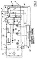
- the floor converter 3 is directly connected to the output of the rectifier stage 15 without adding a filter, and a inductance L is arranged between the top common point of the converter stage 3 and the energy return stage 4.
- the rectifier stage 15 can have the structure classic of a bridge with four diodes.
- the converter stage 3 is of the C-Dump type. It includes a high line 21 and a low line 22 respectively connected to the terminals of outlet of rectifier stage 15, and three branches connected in parallel each with a switch of power T1, T2, T3, for example an IGBT transistor, connected on the one hand, to a terminal of a phase of the motor 100, and on the other hand at the low line 22.
- the three phases Lph1, Lph2, Lph3 are connected in star and their connection common is connected to the upper line of the floor converter 3.
- a freewheeling diode 18 is conventionally provided between the high and low lines 21, 22 to ensure continuity of the current drawn by the converter stage 3 and thus avoid overvoltages.
- AT each connection point of a switch T1, T2, T3 and of the Lph1, Lph2, Lph3 phase associated with it is connected the anode of a demagnetization diode D1, D2, D3.
- the energy return stage 4 includes in series a storage capacitor C, a hash switch TH and a diode 16.
- a control device 23 of system 1 includes a control module 10 for the TH hash and a control module 35 of the three phase switches T1, T2, T3.
- the control module hash 10 receives a voltage measurement 11 rectified power supply, a measurement 12 of the aux voltage storage capacitor C terminals, a measurement 13 of rectified supply current Ia supplied to the terminals of a shunt 29, and in return generates order orders of the TH hash switch and control commands 14 of the phase control module 35.
- This receives also position information of the motor rotor, supplied for example by an angular position sensor, and operating instructions, for example, a speed setpoint, and in return generates orders control of phase switches T1, T2, T3.
- the rectifier stage 15 delivers a rectified voltage in the form of full-wave arches.
- the flow rectified supply Ia supplied by this rectifier stage 15 is a function of the different phase switches which are performed at variable frequency.
- the objective of method according to the invention is to tend towards a current rectified power supply which would present a waveform homothetic of that of the rectified tension.
- Each phase Lph1, Lph2, Lph3 of motor 100 is subjected to successive magnetization (M) and demagnetization (D) at the rate of phase switching.
- the feeding method according to the invention can be implemented regardless of the level of superimposition between respective magnetization sequences and demagnetization concerning the different phases of the engine.
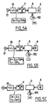
- a magnetization sequence (M) of a given motor phase electrical energy is transferred from source 17, via rectifier stage 15 and a branch of the converter stage 3, towards a phase of the engine where it is for a part converted into form of mechanical energy and for another part stored under form of magnetic energy in the motor (Figure 3A).
- the supply current Ia is then equal to the sum of currents in the three phases of the motor.
- the corresponding phase switch is again blocked, then begins a demagnetization sequence (D) during which the magnetic energy stored in the motor 100 is transferred via the demagnetization diode in the storage capacitor as energy electrostatic ( Figure 3B).
- the rectifier stage 4 continues to supply electrical energy to the system.
- Hash stage 4 is controlled in passing mode on the one hand, when the voltage across the storage capacitor exceeds a value safety limit, and secondly, when the current power supply becomes greater than a setpoint linked to a referenced current wave.
- the hash is thus performed at a hash frequency and at a ratio cyclical variables.
- R dismissal sequence of energy
- Supply current Ia is then equal to the difference between the sum ⁇ Iph of currents in the motor phases and the current Ic delivered by the storage capacitor C.
- hash switch is then switched to blocked mode and the forwarding sequence of energy is over.
- the TH hash switch command not effective only when the voltage measured across the capacitor storage C is greater than the supply voltage rectified measured.
- An essential difference in the feeding process according to the invention with conventional methods resides in the fact that we correct current disturbances supply without adding power components additional, applying a reporting regime variable cyclic to the chopper switch of the assembly C-Dump.
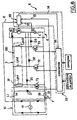
- the supply circuit 6 comprises a rectifier stage 15, a filtering stage F, a stage converter 3 connected to the three phases of a motor electronic reluctance variable reluctance 100, and a energy return stage 4.
- the filtering stage F includes for example a passive filter comprising conventionally an inductance L1 and a capacitor C1, and a diode D 'to isolate on the one hand the filtering stage and on the other hand the converter stage during the sequence of reference.
- the energy return stage 4 is, in this particular embodiment, directly connected to converter stage 3 without addition of inductance, nor of freewheeling diode in parallel on the stage of hash.
- FIGS. 4 and 5A to 5C The magnetization and demagnetization sequences (FIGS. 5A and 5B) are similar to the sequences described for the first embodiment, except for the fact that the filtering stage F is used.
- the energy return sequences (R) when the chopping switch TH is controlled in on mode, the voltage across the terminals of the storage capacitor C is directly applied to the high line 21. As this voltage is then necessarily higher at the rectified supply voltage, the diode D 'is blocked and the supply current Ia will then decrease.
- the diode D As soon as a blocking command is applied to the hash switch TH, the diode D 'becomes on again and the rectified supply current then tends to increase. We show that a modest dimensioning filter is sufficient.
- the supply current Ia is equal to the current absorbed Ic1 by the filtering capacitor C1, while the current Ic supplied by the capacitor C is equal to the magnetizing current flowing in one or more several phases.
- the chopping control modules 10, 20 preferably including a power factor correction circuit (PFC) which delivers a signal indicative of the low or high nature of the supply current, from the reference current information (obtained in practice from the measurement of the rectified supply voltage) and from the supply current information actually measured.
- PFC power factor correction circuit
- FIG. 6 illustrates a variant of the circuit of Figure 4, in which we have given the same references to identical components and modules already described with reference to FIG. 4.
- This variant differs from the supply circuit shown FIG. 4 only by the fact that the filtering stage F includes, in addition to the inductor L1 arranged in the line high 21 of the circuit, a diode D "disposed between the high 21 and low 22 lines of the circuit, the anode of this diode being connected to the bottom line 22.
- this stage filtering F has the advantage of being notably simplified, hence a reduction in its production cost. How this variant of the circuit works supply, as well as energy transfers carried out during the different process sequences according to the invention are similar to those described in reference to FIGS. 5A to 5C.
- Phase and chopping switches can be transistors of any technology, for example bipolar, MOSFET or IGBT transistors.
- Control modules can be implemented in logic wired or programmed and include a microcontroller.
- the supply circuits according to the invention can be integrated as ASIC circuits or well be made from discrete components.
Landscapes
- Engineering & Computer Science (AREA)
- Power Engineering (AREA)
- Dc-Dc Converters (AREA)
- Control Of Electric Motors In General (AREA)
- Rectifiers (AREA)
Claims (14)
- Verfahren zur Versorgung eines elektronisch kommutierten Reluktanzmotors (100) mit variabler Reluktanz von einer Einphasen-Wechselstromquelle (17) mitdadurch gekennzeichnet, daß es eine Steuerung der zur Gleichrichterstufe (15) zurückgeführten Energie umfaßt, um die Störungen des gleichgerichteten Versorgungsstroms (Ia) zu korrigieren.einer Gleichrichtung der von der Einphasen-Wechselstromquelle (17) gelieferten Spannung in einer Gleichrichterstufe (15), um eine gleichgerichtete Spannung zu liefern,nacheinander, für jede der Phasen (Lph1, Lph2, Lph3) dieses Motors (100):einem Magnetisierungsschritt (M) der Phase (Lph1, Lph2, Lph3) mit einer Energieübertragung von der Gleichrichterstufe (15) zu dieser Phase (Lph1, Lph2, Lph3), an die man die gleichgerichtete Spannung anlegt durch Schließen der Kommutierungsvorrichtung (T1, T2, T3), die zu dieser Phase (Lph1, Lph2, Lph3) gehört,einem Entmagnetisierungsschritt (D) dieser Phase (Lph1, Lph2, Lph3) mit einer Energieübertragung von dieser Phase (Lph1, Lph2, Lph3) zu einem für die Gesamtheit der Phasen (Lph1, Lph2, Lph3) gemeinsamen Speicherkondensator (C) beim Öffnen der Kommutierungsvorrichtungen (T1, T2, T3) undRückführungsschritten (R) der im Speicherkondensator (C) gespeicherten Energie zur Gleichrichterstufe (15) durch Steuerung von in Reihe mit dem Speicherkondensator (C) liegenden Zerhackervorrichtung (TH),
- Verfahren nach Anspruch 1, dadurch gekennzeichnet, daß man die Störungen des gleichgerichteten Versorgungsstroms (Ia) bezüglich einer Referenz-Stromwelle korrigiert.
- Verfahren nach einem der Ansprüche 1 oder 2, dadurch gekennzeichnet, daß die Steuerung der zurückgeführten Energie eine Modulation des zyklischen Zerhakkertastverhältnisses umfaßt.
- Verfahren nach Anspruch 3, dadurch gekennzeichnet, daß das zyklische Zerhackertastverhältnis um einen im wesentlichen konstanten Mittelwert herum moduliert wird.
- Verfahren nach Anspruch 4, dadurch gekennzeichnet, daß der Mittelwert des zyklischen Zerhackertastverhältnisses in der Nähe von ½ liegt.
- Verfahren nach einem der vorangehenden Ansprüche, dadurch gekennzeichnet, daß es außerdem eine Messung des gleichgerichteten Versorgungsstroms (Ia) und einen Vergleich dieses gemessenen Stroms mit der Wellenform des Referenzstroms umfaßt, um die zu korrigierenden Störungen zu bestimmen.
- Verfahren nach einem der vorangehenden Ansprüche, dadurch gekennzeichnet, daß während des Energierückführungsschritts (R) eine Induktivität (L) die als magnetischer Puffer wirkt, zwischen den Speicherkondensator (C) und die Gleichrichterstufe (15) eingeschaltet ist.
- Verfahren nach einem der Ansprüche 1 bis 6, dadurch gekennzeichnet, daß während des Schritts der Energierückführung (R) die im Speicherkondensator (C) gespeicherte Energie direkt zur Gleichrichterstufe (15) übertragen wird und daß das Verfahren außerdem eine Filterstufe des gleichgerichteten Versorgungsstroms (Ia) umfaßt.
- Verfahren nach einem der vorangehenden Ansprüche, dadurch gekennzeichnet, daß es außerdem eine Korrektur des Leistungsfaktors der Gesamtheit Motor/Umformer in Abhängigkeit insbesondere von der Messung der gleichgerichteten Versorgungsspannung und des gleichgerichteten Versorgungsstroms umfaßt.
- Schaltkreis zur Versorgung eines elektronisch kommutierten Reluktanzmotors (100) mit variabler Reluktanz mitdadurch gekennzeichnet, daß die Steuervorrichtungen (23, 10, 20, 35) so ausgebildet sind, daß sie die Zerhackervorrichtung (TH) gemäß einem variablen zyklischen Verhältnis so steuern, daß die am gleichgerichteten Versorgungsstrom (Ia) beobachteten Störungen korrigiert werden.einer Gleichrichterstufe (15), die ausgehend von einer Einphasen-Wechselspannungsquelle (17) eine gleichgerichtete Spannung liefert,einer Umformerstufe (3), die jede der Phasen (Lph1, Lph2, Lph3) des Motors (100) versorgt, wobei diese Umformerstufe (3) für jede Phase (Lph1, Lph2, Lph3) Phasen-Kommutierungsvorrichtungen (T1, T2, T3) aufweist, die so gesteuert sind, daß sie in einem bestimmten Zeitfenster die Phase (Lph1, Lph2, Lph3) durch Anlegen der gleichgerichteten Spannung magnetisieren, wobei diese Phasen-Kommutierungsvorrichtungen (T1, T2, T3) außerdem so gesteuert sind, daß sie die Phase (Lph1, Lph2, Lph3) durch Übertragung der in dieser Phase (Lph1, Lph2, Lph3) gespeicherten magnetischen Energie zu einem für die Gesamtheit der Phasen des Motors (100) gemeinsamen Speicherkondensator (C) entmagnetisieren,einer Vorrichtung (4), welche die im Speicherkondensator (C) gespeicherte Energie zur Gleichrichterstufe (15) zurückführr, wobei diese Vorrichtung eine Zerhackervorrichtung (TH) umfaßt, undVorrichtungen (23, 10, 20, 35), welche die Phasen-Kommutierungsvorrichtungen (T1, T2, T3) und die Zerhackervorrichtung (TH) in Abhängigkeit von Betriebseinstellwerten und Meßwerten elektrischer Größen besonders des gleichgerichteten Versorgungsstroms und der Spannung an den Klemmen des Speicherkondensators steuern;
- Schaltkreis nach Anspruch 10, dadurch gekennzeichnet, daß er außerdem eine Induktivität (L) umfaßt, die zwischen der Zerhackervorrichtung (4) und der Umformerstufe (3) angeordnet ist und als magnetischer Puffer wirkt.
- Schaltkreis nach Anspruch 10, dadurch gekennzeichnet, daß die Zerhackervorrichtung (4) direkt mit der Umformerstufe (3) verbunden ist und daß der Schaltkreis außerdem eine Filterstufe (F) aufweist, die zwischen der Gleichrichterstufe (15) und der Konvertierungsstufe (3) angeordnet ist.
- Schaltkreis nach Anspruch 12, dadurch gekennzeichnet, daß die Filterstufe (F) eine Induktivität (L1) umfaßt, die in der oberen Leitung (21) der Gleichrichterstufe (15) angeordnet ist, und eine Diode (D") umfaßt, die zwischen der oberen Leitung (21) und unteren Leitung (22) der Gleichrichterstufe angeordnet ist, wobei die Anode der Diode (D") mit der unteren Leitung (22) verbunden ist.
- Schaltkreis nach einem der Ansprüche 10 bis 13, dadurch gekennzeichnet, daß die Steuervorrichtung (23) eine Vorrichtung umfaßt, die den Leistungsfaktor der Gesamtheit Motor/Umformer korrigiert.
Applications Claiming Priority (3)
| Application Number | Priority Date | Filing Date | Title |
|---|---|---|---|
| FR9600674 | 1996-01-22 | ||
| FR9600674A FR2743955B1 (fr) | 1996-01-22 | 1996-01-22 | Procede pour alimenter un moteur a reluctance variable a commutation electronique et circuit d'alimentation pour sa mise en oeuvre |
| PCT/FR1997/000109 WO1997027665A1 (fr) | 1996-01-22 | 1997-01-20 | Procede pour alimenter un moteur a reluctance variable a commutation electronique et circuit d'alimentation pour sa mise en oeuvre |
Publications (2)
| Publication Number | Publication Date |
|---|---|
| EP0876705A1 EP0876705A1 (de) | 1998-11-11 |
| EP0876705B1 true EP0876705B1 (de) | 2003-08-27 |
Family
ID=9488326
Family Applications (1)
| Application Number | Title | Priority Date | Filing Date |
|---|---|---|---|
| EP97901127A Expired - Lifetime EP0876705B1 (de) | 1996-01-22 | 1997-01-20 | Verfahren zur versorgung eines elektronisch kommutierten reluktanzmotors und schaltkreis zur durchführung des verfahrens |
Country Status (5)
| Country | Link |
|---|---|
| US (1) | US6014001A (de) |
| EP (1) | EP0876705B1 (de) |
| DE (1) | DE69724409T2 (de) |
| FR (1) | FR2743955B1 (de) |
| WO (1) | WO1997027665A1 (de) |
Cited By (1)
| Publication number | Priority date | Publication date | Assignee | Title |
|---|---|---|---|---|
| CN107356870A (zh) * | 2017-06-15 | 2017-11-17 | 中国矿业大学 | 开关磁阻电机功率变换器电流比积分均值差故障诊断方法 |
Families Citing this family (14)
| Publication number | Priority date | Publication date | Assignee | Title |
|---|---|---|---|---|
| DE19709264A1 (de) * | 1997-03-06 | 1998-09-10 | Hilti Ag | Verfahren zur Reduzierung von Rückwirkungen auf den Verlauf des einem Netz entnommenen Stroms bei induktiven Lasten und Vorrichtung zum Antreiben von Motoren nach diesem Verfahren |
| GB9818878D0 (en) * | 1998-08-28 | 1998-10-21 | Switched Reluctance Drives Ltd | Switched reluctance drive with high power factor |
| JP2000125585A (ja) * | 1998-10-12 | 2000-04-28 | Denso Corp | リラクタンス型電動機 |
| WO2001011763A1 (en) * | 1999-08-06 | 2001-02-15 | The Regents Of The University Of California | Unified constant-frequency integration control of three-phase power factor corrected rectifiers, active power filters, and grid-connected inverters |
| US6545887B2 (en) * | 1999-08-06 | 2003-04-08 | The Regents Of The University Of California | Unified constant-frequency integration control of three-phase power factor corrected rectifiers, active power filters and grid-connected inverters |
| ES2252043T3 (es) * | 1999-08-17 | 2006-05-16 | Black & Decker Inc. | Control de una maquina electrica de reclutancia. |
| US6690594B2 (en) * | 2000-08-10 | 2004-02-10 | Sal G. Amarillas | Electrical power conservation apparatus and method |
| IT1319504B1 (it) * | 2000-12-04 | 2003-10-20 | St Microelectronics Srl | Circuito di pilotaggio di motori commutati elettronicamente |
| US7049786B1 (en) * | 2002-11-25 | 2006-05-23 | The Texas A&M University System | Unipolar drive topology for permanent magnet brushless DC motors and switched reluctance motors |
| DE102004030460B3 (de) * | 2004-06-24 | 2005-06-30 | Hans Hermann Rottmerhusen | Elektromotorischer Antrieb für ein Fahrzeug |
| JP5375715B2 (ja) * | 2010-03-31 | 2013-12-25 | 株式会社豊田自動織機 | 中性点昇圧方式の直流−三相変換装置 |
| JP5182320B2 (ja) * | 2010-05-11 | 2013-04-17 | 株式会社デンソー | モータ |
| US8937448B2 (en) | 2011-11-21 | 2015-01-20 | Baker Hughes Incorporated | Systems and methods for downhole power factor correction |
| KR20130124787A (ko) * | 2012-05-07 | 2013-11-15 | 삼성전기주식회사 | 2상 스위치 릴럭턴스 모터의 스위칭 제어 장치 및 그 방법 |
Family Cites Families (5)
| Publication number | Priority date | Publication date | Assignee | Title |
|---|---|---|---|---|
| US5115181A (en) * | 1990-10-05 | 1992-05-19 | Emerson Electric Co. | Power converter for a switched reluctance motor |
| US5424624A (en) * | 1993-02-08 | 1995-06-13 | Dana Corporation | Driver circuit for electric actuator |
| GB9408056D0 (en) * | 1994-04-22 | 1994-06-15 | Switched Reluctance Drives Ltd | A control circuit for an inductive load |
| US5710699A (en) * | 1996-05-28 | 1998-01-20 | General Electric Company | Power electronic interface circuits for batteries and ultracapacitors in electric vehicles and battery storage systems |
| US5742146A (en) * | 1996-12-03 | 1998-04-21 | Magnetek, Inc. | Drive circuit for a switched reluctance motor with improved energy recovery using a common dump capacitor and recovering phase circuit |
-
1996
- 1996-01-22 FR FR9600674A patent/FR2743955B1/fr not_active Expired - Lifetime
-
1997
- 1997-01-20 WO PCT/FR1997/000109 patent/WO1997027665A1/fr not_active Ceased
- 1997-01-20 EP EP97901127A patent/EP0876705B1/de not_active Expired - Lifetime
- 1997-01-20 DE DE69724409T patent/DE69724409T2/de not_active Expired - Lifetime
- 1997-01-20 US US09/117,069 patent/US6014001A/en not_active Expired - Fee Related
Cited By (2)
| Publication number | Priority date | Publication date | Assignee | Title |
|---|---|---|---|---|
| CN107356870A (zh) * | 2017-06-15 | 2017-11-17 | 中国矿业大学 | 开关磁阻电机功率变换器电流比积分均值差故障诊断方法 |
| CN107356870B (zh) * | 2017-06-15 | 2020-01-21 | 中国矿业大学 | 开关磁阻电机功率变换器电流比积分均值差故障诊断方法 |
Also Published As
| Publication number | Publication date |
|---|---|
| FR2743955B1 (fr) | 1998-04-10 |
| EP0876705A1 (de) | 1998-11-11 |
| FR2743955A1 (fr) | 1997-07-25 |
| US6014001A (en) | 2000-01-11 |
| DE69724409T2 (de) | 2004-07-08 |
| WO1997027665A1 (fr) | 1997-07-31 |
| DE69724409D1 (de) | 2003-10-02 |
Similar Documents
| Publication | Publication Date | Title |
|---|---|---|
| EP0847338B1 (de) | Elektrisches netzteil mit gemischer anordnung von wechselrichter und wechselstrom-/gleichstromwandler | |
| EP0876705A1 (de) | Verfahren zur versorgung eines elektronisch kommutierten reluktanzmotors und schaltkreis zur durchführung des verfahrens | |
| US20130113283A1 (en) | Charging and distribution control | |
| FR2769770A1 (fr) | Moyen de regulation d'un generateur electrique | |
| EP0879499B1 (de) | Verfahren zum bearbeiten eines elektronisch kommutierten, variablen reluktanzmotors und stromversorgungs-schalkreis dafür | |
| EP1275196B1 (de) | Motor mit phasenwinkelvorlauf | |
| FR2573587A1 (fr) | Circuits de commande d'un moteur a induction | |
| EP1952525A2 (de) | Generator | |
| FR2486328A1 (fr) | Dispositif perfectionne d'economie d'energie pour moteurs a induction | |
| EP2742585B1 (de) | Ac/dc-wandler mit galvanischer isolierung und signalkorrektor | |
| FR2937803A3 (fr) | Dispositif pour la mise en forme d'un courant de charge d'une source de tension continue rechargeable d'un vehicule automobile electrique ou hybride | |
| EP3183795A1 (de) | Batterieladegerät für hochintegriertes elektrisches oder hybrides kraftfahrzeug | |
| EP2961060B1 (de) | Elektrisches Versorgungssystem einer Last und entsprechendes Versorgungsverfahren | |
| CN110086388A (zh) | 离网运行的发电设备及其电压频率控制方法 | |
| EP0567408A1 (de) | Einrichtung zum Betrieb von Entladungslampen und Fahrzeugscheinwerfer mit solch einer Einrichtung | |
| WO2017071947A1 (fr) | Systeme de conversion d'une puissance electrique continue en puissance electrique alternative avec module recuperateur d'energie | |
| FR2893782A1 (fr) | Dispositif de production d electricite pour alternateur a vitesse variable | |
| WO2017037356A1 (fr) | Utilisation d'un système de commande d'une machine électrique tournante polyphasée comportant des moyens de court-circuit de phase, et utilisation de la machine électrique tournante correspondante | |
| EP3539203B1 (de) | Verfahren zur steuerung eines dreiphasigen wechselrichters für eine ladevorrichtung an bord eines elektro- oder hybridfahrzeugs | |
| FR2767428A1 (fr) | Systeme et procede de regulation de vitesse pour moteur a excitation serie, et moteur correspondant | |
| FR3056037A1 (fr) | Systeme de transfert de puissance electrique | |
| WO2012084572A2 (fr) | Convertisseur de puissance ac/dc a facteur de puissance et thdi ameliores | |
| FR3042926A1 (fr) | Procede et dispositif de commande d'une machine tournante electrique | |
| FR2733862A1 (fr) | Dispositif d'alimentation a decoupage | |
| FR2786043A1 (fr) | Procede et systeme d'alimentation d'un moteur a reluctance variable a double saillance |
Legal Events
| Date | Code | Title | Description |
|---|---|---|---|
| PUAI | Public reference made under article 153(3) epc to a published international application that has entered the european phase |
Free format text: ORIGINAL CODE: 0009012 |
|
| 17P | Request for examination filed |
Effective date: 19980824 |
|
| AK | Designated contracting states |
Kind code of ref document: A1 Designated state(s): DE GB IT NL |
|
| 17Q | First examination report despatched |
Effective date: 19990105 |
|
| GRAH | Despatch of communication of intention to grant a patent |
Free format text: ORIGINAL CODE: EPIDOS IGRA |
|
| RAP1 | Party data changed (applicant data changed or rights of an application transferred) |
Owner name: SEB S.A. |
|
| GRAS | Grant fee paid |
Free format text: ORIGINAL CODE: EPIDOSNIGR3 |
|
| GRAA | (expected) grant |
Free format text: ORIGINAL CODE: 0009210 |
|
| AK | Designated contracting states |
Designated state(s): DE GB IT NL |
|
| PG25 | Lapsed in a contracting state [announced via postgrant information from national office to epo] |
Ref country code: IT Free format text: LAPSE BECAUSE OF FAILURE TO SUBMIT A TRANSLATION OF THE DESCRIPTION OR TO PAY THE FEE WITHIN THE PRESCRIBED TIME-LIMIT;WARNING: LAPSES OF ITALIAN PATENTS WITH EFFECTIVE DATE BEFORE 2007 MAY HAVE OCCURRED AT ANY TIME BEFORE 2007. THE CORRECT EFFECTIVE DATE MAY BE DIFFERENT FROM THE ONE RECORDED. Effective date: 20030827 |
|
| REG | Reference to a national code |
Ref country code: GB Ref legal event code: FG4D Free format text: NOT ENGLISH |
|
| REF | Corresponds to: |
Ref document number: 69724409 Country of ref document: DE Date of ref document: 20031002 Kind code of ref document: P |
|
| GBT | Gb: translation of ep patent filed (gb section 77(6)(a)/1977) |
Effective date: 20031221 |
|
| PLBE | No opposition filed within time limit |
Free format text: ORIGINAL CODE: 0009261 |
|
| STAA | Information on the status of an ep patent application or granted ep patent |
Free format text: STATUS: NO OPPOSITION FILED WITHIN TIME LIMIT |
|
| 26N | No opposition filed |
Effective date: 20040528 |
|
| PGFP | Annual fee paid to national office [announced via postgrant information from national office to epo] |
Ref country code: GB Payment date: 20051202 Year of fee payment: 10 |
|
| PGFP | Annual fee paid to national office [announced via postgrant information from national office to epo] |
Ref country code: NL Payment date: 20070131 Year of fee payment: 11 |
|
| GBPC | Gb: european patent ceased through non-payment of renewal fee |
Effective date: 20070120 |
|
| PG25 | Lapsed in a contracting state [announced via postgrant information from national office to epo] |
Ref country code: GB Free format text: LAPSE BECAUSE OF NON-PAYMENT OF DUE FEES Effective date: 20070120 |
|
| NLV4 | Nl: lapsed or anulled due to non-payment of the annual fee |
Effective date: 20080801 |
|
| PG25 | Lapsed in a contracting state [announced via postgrant information from national office to epo] |
Ref country code: NL Free format text: LAPSE BECAUSE OF NON-PAYMENT OF DUE FEES Effective date: 20080801 |
|
| PGFP | Annual fee paid to national office [announced via postgrant information from national office to epo] |
Ref country code: DE Payment date: 20150109 Year of fee payment: 19 |
|
| REG | Reference to a national code |
Ref country code: DE Ref legal event code: R119 Ref document number: 69724409 Country of ref document: DE |
|
| PG25 | Lapsed in a contracting state [announced via postgrant information from national office to epo] |
Ref country code: DE Free format text: LAPSE BECAUSE OF NON-PAYMENT OF DUE FEES Effective date: 20160802 |