EP0876833A2 - Rollschuh- oder Eislaufschuhstruktur und Verfahren zu ihrer Herstellung - Google Patents
Rollschuh- oder Eislaufschuhstruktur und Verfahren zu ihrer Herstellung Download PDFInfo
- Publication number
- EP0876833A2 EP0876833A2 EP98200669A EP98200669A EP0876833A2 EP 0876833 A2 EP0876833 A2 EP 0876833A2 EP 98200669 A EP98200669 A EP 98200669A EP 98200669 A EP98200669 A EP 98200669A EP 0876833 A2 EP0876833 A2 EP 0876833A2
- Authority
- EP
- European Patent Office
- Prior art keywords
- support
- structure according
- skate structure
- skate
- cavity
- Prior art date
- Legal status (The legal status is an assumption and is not a legal conclusion. Google has not performed a legal analysis and makes no representation as to the accuracy of the status listed.)
- Withdrawn
Links
- 238000000034 method Methods 0.000 title claims description 11
- 238000004519 manufacturing process Methods 0.000 title claims description 3
- 239000000463 material Substances 0.000 claims abstract description 40
- 239000004033 plastic Substances 0.000 claims abstract description 10
- 229920003023 plastic Polymers 0.000 claims abstract description 10
- 238000002347 injection Methods 0.000 claims description 10
- 239000007924 injection Substances 0.000 claims description 10
- 238000001746 injection moulding Methods 0.000 claims description 7
- 239000006096 absorbing agent Substances 0.000 claims description 2
- 239000003086 colorant Substances 0.000 description 2
- 238000012986 modification Methods 0.000 description 1
- 230000004048 modification Effects 0.000 description 1
- 238000000465 moulding Methods 0.000 description 1
- 239000007787 solid Substances 0.000 description 1
- 239000000243 solution Substances 0.000 description 1
Images



Classifications
-
- A—HUMAN NECESSITIES
- A63—SPORTS; GAMES; AMUSEMENTS
- A63C—SKATES; SKIS; ROLLER SKATES; DESIGN OR LAYOUT OF COURTS, RINKS OR THE LIKE
- A63C1/00—Skates
-
- A—HUMAN NECESSITIES
- A63—SPORTS; GAMES; AMUSEMENTS
- A63C—SKATES; SKIS; ROLLER SKATES; DESIGN OR LAYOUT OF COURTS, RINKS OR THE LIKE
- A63C17/00—Roller skates; Skate-boards
- A63C17/18—Roller skates; Skate-boards convertible into ice or snow-running skates
Definitions
- the present invention relates to a skate structure according to the preamble to the main claim and also to a method for the manufacture thereof.
- the support of the running means be it a blade (for an ice skate) or a plurality of in-line wheels (for an in-line roller skate), to be made of plastics material by the injection moulding technique.
- These supports normally have to have a certain stiffness, particularly torsional stiffness, which is achieved by the selection of suitable dimensions of the cross-sections of the support, and at the same time, to have resilience properties such as to absorb the knocks and vibrations to which the skate is subjected during skating. Moreover, the satisfaction of both of these requirements is particularly important for some types of skates such as, for example, competition speed skates. In this field, greater torsional stiffness together with a particularly light weight of the skate are in fact generally required.
- Skate structures having supports according to the prior art therefore generally have a compromise solution which thus limits the performance which can be achieved by these skate structures.
- the problem upon which the present invention is based is that of providing a skate structure which is designed structurally and functionally to overcome all of the problems complained of with reference to the prior art mentioned.
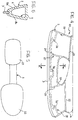
- a first embodiment of an ice-skate structure formed in accordance with the present invention is generally indicated 1.
- the skate structure 1 comprises a blade-holder support 2 for fixing the blade 3 to footwear 4 shown only partially in Figure 1.
- a cavity 5 defined in the support 2 has a hollow cross-section with a closed outline 6, as shown in Figure 3.
- the cavity 5 extends through the entire length of the support 2 between the blade 3 and an opposed element 7 for the attachment of the footwear 4.
- the support 2 has a V-shaped cross-section with sides 8a, b which converge at a vertex position in which the blade 3 is fixed to the support 2, and which are connected to one another at their opposite free ends by the attachment element 7 so as to define the closed outline 6 of the hollow cross-section.
- the attachment element 7 has flanges 9a, b projecting on opposite ends of the free ends of the sides 8a, b.
- Appendages 3a formed in the blade 3 are provided for securing the blade when they are incorporated in the support 2 during the moulding thereof.
- the support 2 is made of plastics material by injection moulding and the cavity 5 is formed inside the support 2 by the gas-injection moulding technique.
- This technique is described, for example, in the leaflet "Arburg-515.202W00296.TI SV I".
- the cavity 5 is thus defined by fairly thin walls of the support 2, having a substantially uniform thickness, indicated S in Figure 3.
- the moulded support 2 is hollow internally with an approximately tubular and monolithic structure.
- the hollow cross-section with a closed outline 6 advantageously provides the support with a certain torsional stiffness, particularly by virtue of the greater moment of inertia in comparison with that which can be achieved with solid cross-sections of the same surface area.
- the cavity 5 may also be filled with a filling material, for example, by the injection of a plastics material after the gas-injection step.
- the filling material is selected, in particular, so as to have a modulus of elasticity lower than that of the material of which the support 2 is made.
- a plastics material with a low density, particularly lower than of the material of the support, is preferably used as the filling material so as to limit the overall weight of the skate structure 1.
- the characteristics of the material filling the cavity are such that it can perform a shock-absorbing function inside the support 2, conferring thereon the ability to absorb knocks and vibrations.
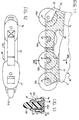
- a second embodiment of the ice-skate structure according to the present invention is generally indicated 20. Details similar to those of the previous embodiment are indicated by the same reference numerals.
- the skate structure 20 has two spaced-apart attachment elements 21, 22 for the footwear 4, between which elements a recess 23 is defined.
- Walls 24, 25 are provided inside the cavity 5 of the support and define in the cavity three adjacent chambers indicated 26, 27, 28, respectively.
- the chambers 26, 28 are formed on opposite sides of the chamber 27 and are defined, on the opposite side to the vertex for the attachment of the blade 3, by the respective attachment elements 21, 22.
- the chamber 27 extends in the centre of the support 2 adjacent the recess 23 and is defined at longitudinally opposite ends by the walls 24, 25.
- the walls may advantageously be formed in the cavity 5 during the gas-injection step so as to have a thickness such as advantageously to constitute stiffening elements for the tubular structure of the support 2. It can be seen that each of the chambers 26-28 has a hollow cross-section with a closed outline as shown, in a manner limited to the chamber 27, in Figure 6.
- Figures 7 and 8 show a third embodiment of the invention, generally indicated 30, which differs from the skate structure 20 by the different orientation of the walls 24, 25.
- the walls 24, 25 extend substantially longitudinally relative to the support 2 so as to define a first closed chamber 31 extending between the opposite longitudinal ends of the support and a second and a third chamber 32, 33, formed above the chamber 31 and extending on opposite sides of the recess 23 up to and also affecting the corresponding attachment elements 21, 22.
- the chambers 32, 33 are open in the region of the respective attachment elements 21, 22 ( Figure 8) in the region of the flanges 9a, b.
- the chambers 32, 33 may be formed with hollow cross-sections with closed outlines as provided for in the previous embodiment.
- the chambers defined in the cavities 5 of the skates 20 and 30 are filled in the manner described for the skate 1 with a filling material having the characteristics described for the skate 1.
- a fourth embodiment of an ice-skate structure according to the invention is generally indicated 40, its blade-holder support 2 having a configuration approximately the same as that of the skate 1 with a cavity 5 and a single chamber extending through the entire length of the support.
- the skate 40 differs from the preceding embodiments in that the cavity 5 is defined in section by the converging sides 8a, b and by a sole 41 fitted on the flanges 9a, b to close the cavity 5.
- the support 2 may be formed with a configuration having a closed, hollow cross-section substantially the same as that of the skate 1 of Figure 3, with the sole 41 co-moulded with the support or fitted on the support subsequently.
- the sole 41 comprises two respective integral cradles 42, 43 for housing corresponding toe and heel portions of the footwear 4 in order to fix the footwear to the support 2.
- the sole 41 may be made of a material having a modulus of elasticity different from the modulus of elasticity of the material of which the support 2 is made.
- the sole 41 is preferably made of a plastics material having a modulus of elasticity lower than that of the support.
- the support 2 and the sole 41 may be made of materials of different colours so as to provide the skate with a particular aesthetic impact.
- the cavity 5 may be filled with a filling material preferably of low density and having resilience properties such as to confer on the skate the ability to absorb knocks and vibrations.
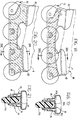
- a first embodiment of an in-line roller-skate structure according to the present invention is generally indicated 50.
- the structure 50 comprises a support 52 with two opposed side walls 53, 54 between which four spaced-apart, aligned wheels 55a-d with parallel axles are supported for rotation.
- the support 52 comprises, on the opposite side to the wheels 55a-d, two spaced-apart attachment elements 56, 57 between which a recess 58 is defined.
- the support 52 is intended to be fixed to the footwear 4, shown only partially in the drawing, by means of the attachment elements 56, 57.
- Each side wall 53, 54 defines a respective cavity 59, 60 having a hollow cross-section with a closed outline 61 as shown in Figure 13.
- Each cavity 59, 60 extends through the entire length of the support 52 between the axles of the wheels 55a-d and the respective attachment elements 56, 57.
- Each side wall 53, 54 is V-shaped with sides 62a, b converging at a vertex position approximately corresponding to the axles on which the wheels are mounted on the support, the sides 62a, b being connected to one another at their opposite free ends so as to define the closed outline 61 of the hollow cross-section.
- each side wall has a respective recess 63 which reduces the hollow cross-section to a substantially trapezoidal configuration as shown in Figure 13.
- the support 52 is made of plastics material by injection moulding and the cavities 59, 60 are formed within the respective side walls 53, 54, as in the embodiments described above, by the gas-injection moulding technique.
- each cavity 59, 60 is defined by thin walls of the support 52 having a uniform thickness, indicated T in Figure 13.
- the moulded support 52 has a hollow interior and has a monolithic tubular structure with a hollow cross-section having a closed outline, conferring particular torsional stiffness on the support.
- Each cavity 59, 60 may also be filled with a filling material, for example, a plastics material injected after the gas injection.
- the filling material selected preferably has a modulus of elasticity lower than the modulus of elasticity of the support 52 and a low density so as to perform the function of a shock-absorber inside the support and to limit the overall weight of the skate structure.
- the selection of a filling material with these physical and resilience properties also confers on the skate structure thus formed an increased ability to absorb knocks.
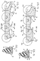
- Figures 14 and 15 show a second embodiment of an in-line roller-skate structure according to the invention, generally indicated 65, of which the details similar to those of the previous embodiment are indicated by the same reference numerals.
- the skate structure 65 differs from the previous embodiment in that walls 66a, 66b are provided inside each cavity 59, 60 and define therein three adjacent chambers indicated 67, 68, and 69, respectively.
- the chambers 67 and 69 are formed on opposite sides of the chamber 68 and are defined on the opposite side to the wheel axles, by the respective attachment elements 56, 57.
- the chamber 68 extends in the centre of the support 52 in the region of the recess 58 and is defined longitudinally by the walls 66a, b.
- These walls which can be formed during the gas injection step, have a thickness such as to constitute stiffening elements for the tubular structure of each side wall.
- Figures 16 and 17 show a third embodiment of an in-line roller-skate structure, generally indicated 70, which differs from the skate structure 65 by a different orientation of the walls 66a, b.
- the walls 66a, b extend longitudinally in each side wall so as to define therein a respective closed chamber 71 extending between the opposite longitudinal ends of the support 52 and a second and a third chamber 72, 73 extending on opposite sides of the recess 58 up to and also affecting the corresponding attachment elements 56, 57 ( Figure 16).
- the chambers 72, 73 may be formed with hollow cross-sections with closed outlines.
- the support 52 differs from that of the previous embodiment in that the cavities 59, 60 are closed by a sole 81 fitted on flanges 82a, b, c projecting from the free ends of the sides 62a, b.
- the support 52 may be formed ( Figure 21) with a configuration having a closed hollow cross-section substantially the same as that of the structure of Figure 11 with the sole 81 co-moulded with the support or fitted thereon subsequently.
- the sole 81 comprises cradles 82, 83 for housing corresponding toe and heel portions of the footwear.
- the sole is made of a material having a modulus of elasticity different from and, in particular, lower than the modulus of elasticity of the support 52.
- the support and the sole may be made of materials of different colours and the cavity may be filled with a low-density filling material as described above for the ice-skate structures.
Landscapes
- Footwear And Its Accessory, Manufacturing Method And Apparatuses (AREA)
Applications Claiming Priority (4)
| Application Number | Priority Date | Filing Date | Title |
|---|---|---|---|
| IT97PD000044 IT1291427B1 (it) | 1997-03-10 | 1997-03-10 | Pattino da ghiaccio e metodo di fabbricazione del medesimo |
| ITPD970044 | 1997-03-10 | ||
| EP97201793 | 1997-06-13 | ||
| EP97201793 | 1997-06-13 |
Publications (2)
| Publication Number | Publication Date |
|---|---|
| EP0876833A2 true EP0876833A2 (de) | 1998-11-11 |
| EP0876833A3 EP0876833A3 (de) | 1999-08-11 |
Family
ID=26146592
Family Applications (1)
| Application Number | Title | Priority Date | Filing Date |
|---|---|---|---|
| EP98200669A Withdrawn EP0876833A3 (de) | 1997-03-10 | 1998-03-05 | Rollschuh- oder Eislaufschuhstruktur und Verfahren zu ihrer Herstellung |
Country Status (3)
| Country | Link |
|---|---|
| EP (1) | EP0876833A3 (de) |
| JP (1) | JPH119755A (de) |
| CA (1) | CA2231287A1 (de) |
Family Cites Families (3)
| Publication number | Priority date | Publication date | Assignee | Title |
|---|---|---|---|---|
| NO158362C (no) * | 1986-03-26 | 1988-08-31 | Jan Bratland | Skoeyte. |
| NL8703017A (nl) * | 1987-12-14 | 1989-07-03 | Eurac Advanced Composites B V | Composiet schaatslichaam, alsmede werkwijzen voor het maken van het composiet schaatslichaam. |
| NL1000493C2 (nl) * | 1995-06-02 | 1996-12-03 | Geert Wemmenhove | Versterkt langwerpig metalen lichaam. |
-
1998
- 1998-03-05 EP EP98200669A patent/EP0876833A3/de not_active Withdrawn
- 1998-03-06 CA CA 2231287 patent/CA2231287A1/en not_active Abandoned
- 1998-03-09 JP JP5712998A patent/JPH119755A/ja active Pending
Non-Patent Citations (1)
| Title |
|---|
| None |
Also Published As
| Publication number | Publication date |
|---|---|
| CA2231287A1 (en) | 1998-09-10 |
| EP0876833A3 (de) | 1999-08-11 |
| JPH119755A (ja) | 1999-01-19 |
Similar Documents
| Publication | Publication Date | Title |
|---|---|---|
| US6345827B1 (en) | Reinforced frame for a skate | |
| US4699432A (en) | Dual material safety wheel | |
| US5411320A (en) | Wheels that provide lateral friction on ice | |
| US4826183A (en) | Skate | |
| EP0496352B1 (de) | Monoski | |
| EP0465794B1 (de) | Ski mit gerippter Oberfläche | |
| CA2195499A1 (fr) | Chaussure de sport | |
| EP1485174A1 (de) | Schuhe zum gehen und rollen | |
| KR20010101076A (ko) | 폼 코어 인-라인 스케이트 프레임 | |
| FR2691909A1 (fr) | Patin à roues en ligne. | |
| AU588850B2 (en) | Ski with damping | |
| US5603522A (en) | Wide short ski | |
| US5799955A (en) | Integrally formed in-line skate having flexible boot and stiff frame | |
| CA2294462C (en) | Sport wearable structure, in particular for in-line and short-tracking roller skates | |
| EP0876833A2 (de) | Rollschuh- oder Eislaufschuhstruktur und Verfahren zu ihrer Herstellung | |
| JP2001505110A (ja) | 操縦能及び制御能を改良したインラインホイール付スケート | |
| US6328317B1 (en) | Article of gliding equipment, such as an in-line roller skate, having a hollow body frame | |
| US20040212165A1 (en) | Skateboard truck and manufacturing method thereof | |
| US7090306B1 (en) | Inline wheel with softer tire and internal support structure | |
| EP1013314A1 (de) | Untergestell der Laufklinge bei Schlittschuhen | |
| EP0867207A2 (de) | Gleitkörperstruktur, insbesondere für Schlittschuhe und in-line Rollschuhe | |
| EP3088061B1 (de) | Rollschuhrahmen, rollski mit besagtem rahmen und verfahren zur herstellung eines rollschuhrahmens | |
| FR2660567A1 (fr) | Ski alpin avec un rapport determine entre la largeur et la longueur. | |
| EP0595732A1 (de) | Langlauf-Skischuh mit verstärkter Sohle | |
| EP0962239A1 (de) | Rad, insbesondere für Rollschuhe |
Legal Events
| Date | Code | Title | Description |
|---|---|---|---|
| PUAI | Public reference made under article 153(3) epc to a published international application that has entered the european phase |
Free format text: ORIGINAL CODE: 0009012 |
|
| AK | Designated contracting states |
Kind code of ref document: A2 Designated state(s): AT CH DE FR IT LI |
|
| AX | Request for extension of the european patent |
Free format text: AL;LT;LV;MK;RO;SI |
|
| PUAL | Search report despatched |
Free format text: ORIGINAL CODE: 0009013 |
|
| AK | Designated contracting states |
Kind code of ref document: A3 Designated state(s): AT BE CH DE DK ES FI FR GB GR IE IT LI LU MC NL PT |
|
| AX | Request for extension of the european patent |
Free format text: AL;LT;LV;MK;RO;SI |
|
| RIC1 | Information provided on ipc code assigned before grant |
Free format text: 6A 63C 1/00 A, 6A 63C 1/40 B, 6A 63C 17/06 B |
|
| 17P | Request for examination filed |
Effective date: 19991220 |
|
| AKX | Designation fees paid |
Free format text: AT CH DE FR IT LI |
|
| STAA | Information on the status of an ep patent application or granted ep patent |
Free format text: STATUS: THE APPLICATION HAS BEEN WITHDRAWN |
|
| 18W | Application withdrawn |
Withdrawal date: 20010207 |