EP0876881A2 - Appareil de forage et/ou percussion - Google Patents
Appareil de forage et/ou percussion Download PDFInfo
- Publication number
- EP0876881A2 EP0876881A2 EP98810143A EP98810143A EP0876881A2 EP 0876881 A2 EP0876881 A2 EP 0876881A2 EP 98810143 A EP98810143 A EP 98810143A EP 98810143 A EP98810143 A EP 98810143A EP 0876881 A2 EP0876881 A2 EP 0876881A2
- Authority
- EP
- European Patent Office
- Prior art keywords
- stop
- guide tube
- machining direction
- stop shoulder
- control body
- Prior art date
- Legal status (The legal status is an assumption and is not a legal conclusion. Google has not performed a legal analysis and makes no representation as to the accuracy of the status listed.)
- Granted
Links
- 238000009527 percussion Methods 0.000 title 1
- 238000003754 machining Methods 0.000 claims abstract description 37
- 238000005553 drilling Methods 0.000 claims abstract description 15
- XAGFODPZIPBFFR-UHFFFAOYSA-N aluminium Chemical compound [Al] XAGFODPZIPBFFR-UHFFFAOYSA-N 0.000 claims description 4
- 229910052782 aluminium Inorganic materials 0.000 claims description 4
- 238000013016 damping Methods 0.000 description 4
- 229910000831 Steel Inorganic materials 0.000 description 3
- 238000006073 displacement reaction Methods 0.000 description 3
- 239000010959 steel Substances 0.000 description 3
- 238000004519 manufacturing process Methods 0.000 description 2
- 239000007787 solid Substances 0.000 description 2
- 238000005516 engineering process Methods 0.000 description 1
- 238000007789 sealing Methods 0.000 description 1
- 239000000758 substrate Substances 0.000 description 1
Images
Classifications
-
- B—PERFORMING OPERATIONS; TRANSPORTING
- B25—HAND TOOLS; PORTABLE POWER-DRIVEN TOOLS; MANIPULATORS
- B25D—PERCUSSIVE TOOLS
- B25D11/00—Portable percussive tools with electromotor or other motor drive
- B25D11/06—Means for driving the impulse member
- B25D11/12—Means for driving the impulse member comprising a crank mechanism
- B25D11/125—Means for driving the impulse member comprising a crank mechanism with a fluid cushion between the crank drive and the striking body
-
- B—PERFORMING OPERATIONS; TRANSPORTING
- B25—HAND TOOLS; PORTABLE POWER-DRIVEN TOOLS; MANIPULATORS
- B25D—PERCUSSIVE TOOLS
- B25D2250/00—General details of portable percussive tools; Components used in portable percussive tools
- B25D2250/035—Bleeding holes, e.g. in piston guide-sleeves
Definitions
- the invention relates to a drilling and / or chiseling device according to the preamble of Claim 1.
- From DE-PS 26 41 070 is a drilling and / or chiseling device with a guide tube known, wherein a piston of a striking mechanism and a striker axially in the guide tube are arranged displaceable. That points between the piston and the racket Guide tube on a radially extending air passage, the opposite of one the guide tube axially displaceable control body is closable.
- the air outlet When the air outlet is open, the interior of the guide tube is ventilated so that no pressure can be built up by the piston of the hammer mechanism in the guide tube is necessary for an axial displacement of the racket in the machining direction. If the air passage is closed by the control body, inside the Guide tube between the racket and the piston a pressure is built up.
- a stop of the control body designed as a bottom acts with a first one Stop shoulder of an axially displaceable arranged coaxially to the guide tube Döppers together.
- the air outlet should be released as soon as possible, so that the piston in the interior of the guide tube no longer build up pressure and the racket, the striking tool and the drilling or chisel tool in the machining direction can no longer move.
- a quick release of the air passage is achieved by moving the control body in its machining direction as quickly as possible Starting position is shifted.
- control body Since the entire contact pressure is transmitted to the housing via the control body, the control body must be very solid and very high strength have, which leads to a high weight.
- a quick transfer of this massive control body into Machining direction is by means of a strong, also solid spring, which is supported against the machine direction on the housing of the device and cooperates with the control body.
- the high weight of the spring and the Control body has a negative effect on the total weight of the device. By the high total weight, handling the device is poor and it turns out to be a rapid operator fatigue.
- the invention has for its object to provide a drilling and / or chisel device, which has a low overall weight, is easy to use, economical can be manufactured and operated safely.
- the control body which interacts with the first stop shoulder of the striker has a low strength and a low weight.
- the individual parts of the Control elements are, for example, very thin-walled and have little Dimensions. Since the control body according to the invention is very light, this can also be moved parallel to the machining direction with very little force.
- the at Lifting the device off a surface for moving the control body into Machining direction provided spring has a low spring force and a low Dead weight on. The fact that the spring and the individual parts of the control body A device with a low weight can have a low weight be created.
- the second expediently towers above Stop shoulder the first stop shoulder radially.
- the second stop shoulder and the stop surface is designed as an annular surface.
- the circular surface of the second shoulder should be conical, opposed tapering the machining direction and the circular surface of the stop surface conical, widened in the machining direction.
- control body is preferably one Shift fork, a shift rod and a shift sleeve formed, the one with the first Stop shoulder cooperating stop of the control body from the shift fork is formed.
- the weight of the control element is kept very small by advantageously Shift fork and the shift rod are integrally formed.
- a tour of the Shift rod parallel to the machining direction takes place, for example, in at least one slot-like, extending parallel to the machining direction of the Guide tube through which the shift fork into the interior of the guide tube protrudes.
- the thickness measured perpendicular to the machining direction is at least that Shift rod corresponds essentially to the wall thickness of the guide tube, for example.
- the shift rod and the shift sleeve are expediently formed in one piece.
- the control body is preferably at least partially made of plastic.
- control body is expediently made at least partially of aluminum.
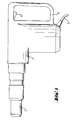
- the drilling and / or chiseling device shown schematically in FIG. 1 has one Housing 1 with a handle 3, a switch 4, a tool holder 2 for a not shown tool and an electric cable 5, through which the device with a external power source is connectable.
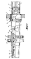
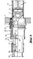
- FIGS. 2 to 3 there is a inside of the drilling and / or chiseling device extending parallel to the machining direction guide tube 9 with a in Machining direction pointing the first free end and the first free end opposite second free end.
- the piston 7 is not one completely shown striking mechanism 6 axially displaceable.
- the piston 7 is connected via a bolt 8 to a connecting rod, which is the second free end of the Guide tube 9 protrudes counter to the machining direction.
- the guide tube 9 has a plurality of radially extending air passages 10 on, which are arranged between the piston 7 and the racket 21 and on the Pressure of an air cushion buildable by the piston 7 can be influenced.
- the control this air passages 10 takes place by means of the control body, which is made up of a Shift fork 15, 35, a shift rod 14, 34 and a shift sleeve 13, 33 put together.
- a stop 30 of the shift fork 15, 35 acts with a first Stop shoulder 18 of the striker 17 together.
- the second is in the pressed position of the device Stop shoulder 19 of the striker 17 on an axially fixed with the guide tube 9 in Connected stop surface 20. Between the second stop shoulder 19 and the stop surface 20, for example, a damping element 29 is arranged.
- the striker 17 is offset by the striker 21 in the machining direction.
- there is a displacement of the control body in the machining direction by means of a on the switching sleeve 13, 33 of the control body and a bushing 11 supporting spring 12.
- the bushing 11 is pressed into a receiving bore in the housing 1 and supports it against the machining direction on a radially expanded collar Circumferential area of the receiving bore of the housing 1.
- the switching sleeve 13 is sleeve-like and encompasses part of the circumference of the guide tube 9 in the region of the air passages 10.
- the shift fork 15 cooperating with the striker 17 and the Shift rod 14 are formed as a one-piece component and form-fitting with the Switch sleeve 13 connected.
- the component is designed as a wire bracket.
- a first end the wire bracket is shaped as a ring and protrudes into a circumferential recess the switching sleeve 13.
- Another section of the wire bracket protrudes substantially perpendicular from that plane which is formed by the ring and the second end of the
- the wire bracket is bent at a right angle and extends parallel to the ring plane.
- the Wire thickness corresponds essentially to the wall thickness of the guide tube 9 in Area of an opening 16 through which a part of the component into the interior of the Guide tube 9 protrudes.
- the component designed as a wire bracket is made of steel, for example, and the switching sleeve made of steel, plastic or aluminum.
- Fig. 3 shows a control body, the switching sleeve 33 and switching rod 34 as one-piece component are formed, which in positive connection with the Shift fork 35 stands.
- the shift fork 35 is plate-shaped and has one central through hole on the receiving one of the first stop shoulder 18th the striker 17 against the machining direction superior approach.
- the Shift fork 35 has a stop 30, which with the first stop shoulder 18 in Contact is there.
- the component is essentially sleeve-shaped, and has in Area of the shift fork 35 two diametrically opposite one another Openings in which the two free ends of the shift fork 35th can intervene positively.
- the one with the second stop shoulder 19 of the striker 17 cooperating stop surface 20 is formed by the striker guide 28, the axially fixed, for example by means of a press connection with the guide tube 9 in Connection is established.
- the shift fork 35 and the component are made of steel, plastic or Made of aluminum.
- the striker lies 17 on the damping ring 23 and the spring 12 pushes the control body in Machining direction so that the air passages 10 are not covered by the control body will.
- An axial displacement of the striker 17 is not possible because a pressure in Interior of the guide tube 9 between the piston 7 and the racket 21 not can be built.
Landscapes
- Engineering & Computer Science (AREA)
- Mechanical Engineering (AREA)
- Percussive Tools And Related Accessories (AREA)
- Earth Drilling (AREA)
Applications Claiming Priority (2)
| Application Number | Priority Date | Filing Date | Title |
|---|---|---|---|
| DE19714287A DE19714287A1 (de) | 1997-04-07 | 1997-04-07 | Bohr- und/oder Meisselgerät |
| DE19714287 | 1997-04-07 |
Publications (3)
| Publication Number | Publication Date |
|---|---|
| EP0876881A2 true EP0876881A2 (fr) | 1998-11-11 |
| EP0876881A3 EP0876881A3 (fr) | 2002-11-27 |
| EP0876881B1 EP0876881B1 (fr) | 2006-08-23 |
Family
ID=7825676
Family Applications (1)
| Application Number | Title | Priority Date | Filing Date |
|---|---|---|---|
| EP98810143A Expired - Lifetime EP0876881B1 (fr) | 1997-04-07 | 1998-02-23 | Appareil de forage et/ou percussion |
Country Status (5)
| Country | Link |
|---|---|
| US (1) | US5992541A (fr) |
| EP (1) | EP0876881B1 (fr) |
| JP (1) | JPH10309680A (fr) |
| CN (1) | CN1066380C (fr) |
| DE (2) | DE19714287A1 (fr) |
Cited By (1)
| Publication number | Priority date | Publication date | Assignee | Title |
|---|---|---|---|---|
| US9925653B2 (en) | 2013-07-05 | 2018-03-27 | Black & Decker Inc. | Hammer drill |
Families Citing this family (21)
| Publication number | Priority date | Publication date | Assignee | Title |
|---|---|---|---|---|
| DE19929183B4 (de) * | 1999-06-25 | 2004-07-29 | Wacker Construction Equipment Ag | Luftfederschlagwerk mit Hohl-Schlagkolben mit Leerlauföffnung |
| DE19955412A1 (de) * | 1999-11-18 | 2001-05-23 | Hilti Ag | Bohr- und Meisselgerät |
| USD466780S1 (en) | 2000-03-16 | 2002-12-10 | Black & Decker Inc. | Hammer drill |
| DE10019071A1 (de) * | 2000-04-18 | 2001-10-25 | Hilti Ag | Elekrohandwerkzeuggerät mit Leerschlagabschaltung |
| DE10103996C1 (de) * | 2001-01-30 | 2002-10-02 | Wacker Werke Kg | Luftfederschlagwerk für einen Schlag- und/oder Bohrhammer mit kurz bauendem Antriebskolben |
| EP1607187B1 (fr) * | 2004-06-18 | 2010-04-28 | HILTI Aktiengesellschaft | Appareil pour l'amélioration de la réponse en coupure d'un outil électropneumatique à percussion |
| USD527601S1 (en) | 2005-02-10 | 2006-09-05 | Black & Decker Inc. | Hammer |
| USD524626S1 (en) | 2005-02-10 | 2006-07-11 | Black & Decker Inc. | Hammer |
| USD540642S1 (en) | 2005-02-10 | 2007-04-17 | Black & Decker Inc. | Hammer |
| DE102006000395A1 (de) * | 2006-08-07 | 2008-02-14 | Hilti Ag | Handwerkzeugmaschine mit pneumatischem Schlagwerk |
| DE102006060320A1 (de) * | 2006-12-20 | 2008-06-26 | Robert Bosch Gmbh | Schlagwerk für eine Handwerkzeugmaschine |
| DE102007000081A1 (de) * | 2007-02-08 | 2008-08-21 | Hilti Ag | Handwerkzeugmaschine mit pneumatischem Schlagwerk |
| US9216502B2 (en) | 2008-04-03 | 2015-12-22 | Black & Decker Inc. | Multi-stranded return spring for fastening tool |
| US8534527B2 (en) * | 2008-04-03 | 2013-09-17 | Black & Decker Inc. | Cordless framing nailer |
| US9346158B2 (en) | 2012-09-20 | 2016-05-24 | Black & Decker Inc. | Magnetic profile lifter |
| US9399281B2 (en) | 2012-09-20 | 2016-07-26 | Black & Decker Inc. | Stall release lever for fastening tool |
| CN102966673A (zh) * | 2012-12-04 | 2013-03-13 | 普光新高(北京)技术开发有限公司 | 一种电气隔离转轴装置 |
| EP2857149A1 (fr) * | 2013-10-03 | 2015-04-08 | HILTI Aktiengesellschaft | Machine-outil manuelle |
| WO2021202968A1 (fr) * | 2020-04-02 | 2021-10-07 | Milwaukee Electric Tool Corporation | Outil électrique |
| US11833652B2 (en) * | 2022-01-25 | 2023-12-05 | Hilti Aktiengesellschaft | Power tool |
| US12427638B2 (en) | 2022-12-20 | 2025-09-30 | Milwaukee Electric Tool Corporation | Percussion tool |
Family Cites Families (10)
| Publication number | Priority date | Publication date | Assignee | Title |
|---|---|---|---|---|
| US3662843A (en) * | 1970-01-29 | 1972-05-16 | Gen Dynamics Corp | Impact tools |
| DE2641070A1 (de) * | 1976-09-11 | 1978-03-16 | Bosch Gmbh Robert | Motorisch angetriebener schlaghammer mit luftfederung |
| EP0052507B1 (fr) * | 1980-11-18 | 1985-02-13 | Black & Decker Inc. | Perceuse à percussion |
| DE3304916A1 (de) * | 1983-02-12 | 1984-08-16 | Robert Bosch Gmbh, 7000 Stuttgart | Bohrhammer |
| DE3429140A1 (de) * | 1984-08-08 | 1986-02-20 | Black & Decker Inc., Newark, Del. | Bohrhammer mit einem pneumatischen schlagwerk |
| DE3743333A1 (de) * | 1987-12-21 | 1989-07-06 | Bosch Gmbh Robert | Motorisch angetriebener meissel- oder bohrhammer |
| DE3826213A1 (de) * | 1988-08-02 | 1990-02-15 | Bosch Gmbh Robert | Bohr- oder schlaghammer |
| DE3932134A1 (de) * | 1989-09-27 | 1991-04-04 | Bosch Gmbh Robert | Hammer mit luftfederschlagwerk |
| DE4239294A1 (de) * | 1992-11-23 | 1994-05-26 | Black & Decker Inc | Bohrhammer mit pneumatischem Schlagwerk |
| JP3292969B2 (ja) * | 1995-08-18 | 2002-06-17 | 株式会社マキタ | ハンマードリル |
-
1997
- 1997-04-07 DE DE19714287A patent/DE19714287A1/de not_active Withdrawn
-
1998
- 1998-02-23 EP EP98810143A patent/EP0876881B1/fr not_active Expired - Lifetime
- 1998-02-23 DE DE59813693T patent/DE59813693D1/de not_active Expired - Lifetime
- 1998-04-06 JP JP10093528A patent/JPH10309680A/ja active Pending
- 1998-04-06 CN CN98106334A patent/CN1066380C/zh not_active Expired - Lifetime
- 1998-04-07 US US09/056,585 patent/US5992541A/en not_active Expired - Lifetime
Cited By (1)
| Publication number | Priority date | Publication date | Assignee | Title |
|---|---|---|---|---|
| US9925653B2 (en) | 2013-07-05 | 2018-03-27 | Black & Decker Inc. | Hammer drill |
Also Published As
| Publication number | Publication date |
|---|---|
| DE59813693D1 (de) | 2006-10-05 |
| CN1066380C (zh) | 2001-05-30 |
| US5992541A (en) | 1999-11-30 |
| CN1197717A (zh) | 1998-11-04 |
| EP0876881B1 (fr) | 2006-08-23 |
| DE19714287A1 (de) | 1998-10-08 |
| JPH10309680A (ja) | 1998-11-24 |
| EP0876881A3 (fr) | 2002-11-27 |
Similar Documents
| Publication | Publication Date | Title |
|---|---|---|
| EP0876881B1 (fr) | Appareil de forage et/ou percussion | |
| EP0876880B1 (fr) | Appareil de forage et/ou percussion | |
| DE19821554B4 (de) | Bohrgerät mit Schlagwerk | |
| DE3932660C2 (de) | Schlagbohrmaschine mit mechanischer Schlagübertragung | |
| DE2242944A1 (de) | Bohrhammer | |
| DE4340726C1 (de) | Einrichtung an Handwerkzeugmaschinen zur Drehmitnahme von Werkzeugen | |
| CH666216A5 (de) | Handwerkzeugmaschine, insbesondere bohr- oder schlaghammer. | |
| EP0724924B1 (fr) | Porte-outil, en particulier mandrin à changement rapide | |
| DE2252951B2 (de) | Bohrhammer | |
| CH659792A5 (de) | Motorisch angetriebene schlagende handwerkzeugmaschine. | |
| DE2323268B2 (de) | Schlagbohrmaschine | |
| DE2540838C2 (de) | Elektropneumatischer Hammer | |
| DE19540396A1 (de) | Bohr- und/oder Meisselgerät | |
| DE10241054A1 (de) | Werkzeug und Werkzeughalter für eine Handwerkzeugmaschine | |
| DE2328462C2 (de) | Schlagbohrmaschine | |
| DE1652685C3 (de) | Einrichtung zum Umschalten von Schlagbohren auf Drehbohren | |
| EP0768151B1 (fr) | Porte-outil | |
| EP0266305A1 (fr) | Marteau de forage avec mécanisme de percussion | |
| CH673425A5 (fr) | ||
| EP1122033B1 (fr) | Manche d'outil | |
| DE3531641A1 (de) | Bohr- und meisselhammer | |
| EP0768150B1 (fr) | Porte-outil | |
| CH692776A5 (de) | Elektrowerkzeugmaschine. | |
| DE4343583A1 (de) | Bohrhammer | |
| CH669358A5 (fr) |
Legal Events
| Date | Code | Title | Description |
|---|---|---|---|
| PUAI | Public reference made under article 153(3) epc to a published international application that has entered the european phase |
Free format text: ORIGINAL CODE: 0009012 |
|
| AK | Designated contracting states |
Kind code of ref document: A2 Designated state(s): AT BE CH DE DK ES FI FR GB GR IE IT LI LU MC NL PT SE |
|
| AX | Request for extension of the european patent |
Free format text: AL;LT;LV;MK;RO;SI |
|
| PUAL | Search report despatched |
Free format text: ORIGINAL CODE: 0009013 |
|
| AK | Designated contracting states |
Kind code of ref document: A3 Designated state(s): AT BE CH DE DK ES FI FR GB GR IE IT LI LU MC NL PT SE |
|
| AX | Request for extension of the european patent |
Free format text: AL;LT;LV;MK;RO;SI |
|
| 17P | Request for examination filed |
Effective date: 20030527 |
|
| AKX | Designation fees paid |
Designated state(s): CH DE GB LI NL SE |
|
| GRAP | Despatch of communication of intention to grant a patent |
Free format text: ORIGINAL CODE: EPIDOSNIGR1 |
|
| GRAS | Grant fee paid |
Free format text: ORIGINAL CODE: EPIDOSNIGR3 |
|
| GRAA | (expected) grant |
Free format text: ORIGINAL CODE: 0009210 |
|
| AK | Designated contracting states |
Kind code of ref document: B1 Designated state(s): CH DE GB LI NL SE |
|
| REG | Reference to a national code |
Ref country code: GB Ref legal event code: FG4D Free format text: NOT ENGLISH |
|
| REG | Reference to a national code |
Ref country code: CH Ref legal event code: EP |
|
| REF | Corresponds to: |
Ref document number: 59813693 Country of ref document: DE Date of ref document: 20061005 Kind code of ref document: P |
|
| GBT | Gb: translation of ep patent filed (gb section 77(6)(a)/1977) |
Effective date: 20061009 |
|
| REG | Reference to a national code |
Ref country code: SE Ref legal event code: TRGR |
|
| PLBE | No opposition filed within time limit |
Free format text: ORIGINAL CODE: 0009261 |
|
| STAA | Information on the status of an ep patent application or granted ep patent |
Free format text: STATUS: NO OPPOSITION FILED WITHIN TIME LIMIT |
|
| 26N | No opposition filed |
Effective date: 20070524 |
|
| PGFP | Annual fee paid to national office [announced via postgrant information from national office to epo] |
Ref country code: CH Payment date: 20170214 Year of fee payment: 20 Ref country code: DE Payment date: 20170214 Year of fee payment: 20 Ref country code: SE Payment date: 20170213 Year of fee payment: 20 |
|
| PGFP | Annual fee paid to national office [announced via postgrant information from national office to epo] |
Ref country code: NL Payment date: 20170210 Year of fee payment: 20 Ref country code: GB Payment date: 20170222 Year of fee payment: 20 |
|
| REG | Reference to a national code |
Ref country code: DE Ref legal event code: R071 Ref document number: 59813693 Country of ref document: DE |
|
| REG | Reference to a national code |
Ref country code: CH Ref legal event code: PL Ref country code: NL Ref legal event code: MK Effective date: 20180222 |
|
| REG | Reference to a national code |
Ref country code: GB Ref legal event code: PE20 Expiry date: 20180222 |
|
| PG25 | Lapsed in a contracting state [announced via postgrant information from national office to epo] |
Ref country code: GB Free format text: LAPSE BECAUSE OF EXPIRATION OF PROTECTION Effective date: 20180222 |