EP0876892A2 - Tête revolver à vitesse élevée - Google Patents
Tête revolver à vitesse élevée Download PDFInfo
- Publication number
- EP0876892A2 EP0876892A2 EP98810363A EP98810363A EP0876892A2 EP 0876892 A2 EP0876892 A2 EP 0876892A2 EP 98810363 A EP98810363 A EP 98810363A EP 98810363 A EP98810363 A EP 98810363A EP 0876892 A2 EP0876892 A2 EP 0876892A2
- Authority
- EP
- European Patent Office
- Prior art keywords
- turret
- mold
- injection molding
- molding machine
- mold half
- Prior art date
- Legal status (The legal status is an assumption and is not a legal conclusion. Google has not performed a legal analysis and makes no representation as to the accuracy of the status listed.)
- Withdrawn
Links
Images


Classifications
-
- B—PERFORMING OPERATIONS; TRANSPORTING
- B29—WORKING OF PLASTICS; WORKING OF SUBSTANCES IN A PLASTIC STATE IN GENERAL
- B29C—SHAPING OR JOINING OF PLASTICS; SHAPING OF MATERIAL IN A PLASTIC STATE, NOT OTHERWISE PROVIDED FOR; AFTER-TREATMENT OF THE SHAPED PRODUCTS, e.g. REPAIRING
- B29C45/00—Injection moulding, i.e. forcing the required volume of moulding material through a nozzle into a closed mould; Apparatus therefor
- B29C45/03—Injection moulding apparatus
- B29C45/04—Injection moulding apparatus using movable moulds or mould halves
- B29C45/0441—Injection moulding apparatus using movable moulds or mould halves involving a rotational movement
- B29C45/045—Injection moulding apparatus using movable moulds or mould halves involving a rotational movement mounted on the circumference of a rotating support having a rotating axis perpendicular to the mould opening, closing or clamping direction
-
- B—PERFORMING OPERATIONS; TRANSPORTING
- B29—WORKING OF PLASTICS; WORKING OF SUBSTANCES IN A PLASTIC STATE IN GENERAL
- B29C—SHAPING OR JOINING OF PLASTICS; SHAPING OF MATERIAL IN A PLASTIC STATE, NOT OTHERWISE PROVIDED FOR; AFTER-TREATMENT OF THE SHAPED PRODUCTS, e.g. REPAIRING
- B29C45/00—Injection moulding, i.e. forcing the required volume of moulding material through a nozzle into a closed mould; Apparatus therefor
- B29C45/03—Injection moulding apparatus
- B29C45/04—Injection moulding apparatus using movable moulds or mould halves
- B29C45/0441—Injection moulding apparatus using movable moulds or mould halves involving a rotational movement
- B29C45/045—Injection moulding apparatus using movable moulds or mould halves involving a rotational movement mounted on the circumference of a rotating support having a rotating axis perpendicular to the mould opening, closing or clamping direction
- B29C2045/0458—Drive means for the rotating support
-
- B—PERFORMING OPERATIONS; TRANSPORTING
- B29—WORKING OF PLASTICS; WORKING OF SUBSTANCES IN A PLASTIC STATE IN GENERAL
- B29C—SHAPING OR JOINING OF PLASTICS; SHAPING OF MATERIAL IN A PLASTIC STATE, NOT OTHERWISE PROVIDED FOR; AFTER-TREATMENT OF THE SHAPED PRODUCTS, e.g. REPAIRING
- B29C45/00—Injection moulding, i.e. forcing the required volume of moulding material through a nozzle into a closed mould; Apparatus therefor
- B29C45/03—Injection moulding apparatus
- B29C45/04—Injection moulding apparatus using movable moulds or mould halves
- B29C2045/0466—Injection moulding apparatus using movable moulds or mould halves the axial movement of the mould being linked to the rotation of the mould or mould half
Definitions
- This invention is directed to a turret style injection molding machine, and more particularly, to an injection molding machine having a rotating and longitudinally movable turret block with at least one mold half rotatable and movable into engagement with a non-rotatable mold half.
- Injection molding machines having turret configurations for moving mold halves into and out of alignment with other mold halves are well known in the prior art.
- a turret type configuration for injection molding is beneficial since it lends itself to high volume production of molded parts. This is true since different molding related operations can be performed using the turret configuration, simultaneous to the actual molding of the part. That is, while one part is being molded on the turret block, another part having already been molded or to be molded can be subjected to a plurality of post molding or pre-molding operations. These operations include, for example, injecting, holding, cooling and ejecting, each of which can be performed at a different angular position relative the turret block.
- U.S. Patent 4,734,023 to Nesch et al. discloses an injection molding machine which uses a four to eight sided turret block that rotates about a vertical axis and which is mounted between the stationary and moving platens of the machine. The turret is also slidable on lower tie bars between the platens.
- U.S. Patent 4,427,359 to Fukuoka discloses an injection stretch blow molding machine.
- the machine incorporates a four sided turret block positioned on a vertical axis wherein preforms are injection molded in a first position of the four sided turret block.
- Preforms are temperature conditioned inside a second conditioning mold at a second position of the block.
- the preforms are blow molded at a third position and ejected at a fourth.
- U.S. Patent 4,449,913 to Krishnakumar discloses a rotary injection turret for use in making preforms.
- the patent teaches a turret block rotatable on a vertical axis, which block uses two of the turret block positions for post mold treatment of preforms while the preforms are still on mold cores. Accordingly, after injection, hold and some cooling at a first station, the turret block rotates to a second position where cooling fluid is blown onto the exterior surface of the preforms in order to cool the preforms. At a third position, the preforms are inserted into a conditioning mold from the turret block where the gate vestige is trimmed and further temperature conditioning is performed.
- U.S. Patent 4,836,767 to Schad et al. discloses a swing plate molding machine.
- the swing plate molding machine includes two core mold halves and one single cavity mold half. During molding, parts are caused to remain on the cores of the mold halves and are swung to an outboard position where the parts are transferred into a four sided turret block arrangement for continued cooling.
- the turret rotates on a horizontal axis and may contain a mechanism for temperature conditioning at one of its stations.
- U.S. Patent 4,370,124 to Buja discloses a modular rotary molding machine.
- the rotary style machine disclosed has a wheel which rotates about a horizontal axis.
- the entire wheel and additional assembly is mounted on a movable carriage with respect to a fixed injection unit.
- the diameter of the wheel is adjustable to vary the number of molds processed.
- Each mold thereon is filled individually and then clamped and packed by units positioned on board the wheel.
- U.S. Patent 4,243,362 to Rees discloses a composite molding apparatus for molding articles from two materials.
- the apparatus includes a four sided turret block rotatable between two opposed faces about a horizontal axis.
- the block is mounted slidably between a fixed and a moving platen of a horizontal injection molding machine. Two material molding is achieved by injecting different materials from separate injectors when the block is in each of two positions.
- Additional turret style injection molding machines having a horizontal axis of rotation include U.S. Patent 3,988,100 to Julien; U.S. Patent 3,881,855 to Farkas; and U.S. Patent 3,730,665 to Fortin.
- the prior art also includes a plurality of two platen injection molding machines, some of which are discussed as follows.
- U.S. Patent 5,338,171 to Hayakawa discloses a die clamping apparatus with an aligning device.
- the apparatus includes a two platen clamp with alignment means provided by vertically adjustable trunnions under the movable platen.
- the trunnions are moved by cylinders which respond to deflection signals sensed at the ends of outriggers mounted to the moving platen.
- U.S. Patent 5,336,462 to Wohlrab discloses a mold closing apparatus for an injection molding machine.
- the machine includes a two platen clamp in which stroke cylinders are positioned inside tie bars, the ends of which also act as clamp pistons.
- U.S. Patent 5,314,327 to Stein discloses a mold clamp for an injection molding machine.
- the machine includes a two platen clamp with means to help align the mold halves.
- Adjustable rollers are used on a moving platen carriage and adjusting means are built into the carriage/moving platen assembly for improving alignment.
- U.S. Patent Application Serial No. 08/611,362 discloses a turret molding machine using an electric servo drive to rotate the turret.
- the primary object of this invention is to provide an energy and space efficient injection molding machine having a reduced cycle time which includes a longitudinally movable and rotatable turret block.
- Another object of this invention is to provide a two platen injection molding machine including a longitudinally movable and rotatable turret block, wherein the longitudinal and rotational movements are efficiently interrelated, thereby reducing cycle time.
- Yet another object of this invention is to provide an energy, cycle time and space efficient two platen injection molding machine having a rotatable turret block.
- Yet another object of this invention is to provide a two platen injection molding machine using a movable and rotatable turret block which includes at least one and preferably two mold halves movable toward and away from a mating stationary mold half for forming molds for injection molding parts in an energy and cycle time efficient manner.
- the disclosed objects and advantages are achieved by the injection molding machine of the present invention.
- the machine comprises a first mold half having one of at least one mold cavity and at least one mold core and a rotatable turret block rotatable on an axis for rotating at least one movable mold half thereof into alignment with the first mold half.
- Each of the movable mold halves includes one of at least one mold cavity and at least one mold core matable with the first mold half for forming a mold for molding a molded article.
- the rotatable turret block is further for clamping the movable mold halves and the first mold half together.
- the machine further includes means for moving the rotatable turret block relative the first mold half and means for rotating the rotatable turret means, wherein the means for moving is linked to the means for rotating, and a first injection means for injecting melt into the at least one mold cavity.
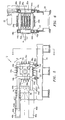
- FIG. 1 an elevational and schematic side view of a turret injection molding machine used in the present invention, which is designated generally as 10.
- Injection molding machine 10 generally includes a rotatable turret block 12 with a plurality of movable mold halves 14a-14d, a stationary mold half and platen 16 and injection unit 18, all positioned on base 20.
- Injection molding machine 10 may be used for molding a variety of different types of articles and accordingly, is not limited for use with any particular type of article. Preforms are referred to throughout this description by way of example only.
- turret block is shown throughout this description as rotatable on a horizontal axis, and this is the preferred embodiment, it is feasible that a similar design of a movable turret block providing the clamping action may be provided which is rotatable on a vertical axis. Accordingly, this invention is not considered limited to the horizontal axis feature.
- turret block 12 is preferably longitudinally movable on base 20 via a set of rollers 22 attached to the bottom of the turret block and thereby providing a mold clamp force.
- Base 20 includes hardened ways 24 which engage rollers 22, wherein rollers 22 engage the underside of ways 24 so as to counteract upward forces and tipping forces that may act on the turret block assembly.
- Turret block 12 is rotatable as shown in FIGS. 1-5 by a motor, as an electric servo drive motor 26 and preferably on a horizonal axis H through arcuate sectors as shown in FIGS. 1-5 of substantially 90°.
- the electric servo drive motor 26 is connected via a belt drive 30 to axis H for rotating turret block 12, as shown in FIG. 4, while the electric servo drive motor is preferably mounted on one of turret block carriages 32a and 32b extending from base 20.
- turret block 12 includes a plurality of movable mold halves, i.e. movable mold halves 14a-14d each of which includes a set of mold cores 34a-34d, respectively, each set having at least one mold core, adapted for engagement with a set of mold cavities 36, each set including at least one mold cavity and located in stationary mold half and platen 16.
- movable mold halves 14a-14d each of which includes a set of mold cores 34a-34d, respectively, each set having at least one mold core, adapted for engagement with a set of mold cavities 36, each set including at least one mold cavity and located in stationary mold half and platen 16.
- four movable mold halves or faces 14a-14d are provided on turret block 12, although any number supportable by the size of the turret block 12 can be used.
- Sets of mold cores 34a-34d are adapted to be rotated into horizontal and vertical alignment with sets of mold cavities 36.
- turret block 12 includes sets of ejector pistons or stripper rings 38a-38d, and a system for the operation thereof, which operate on sets of mold cores 34a-34d and strippers positioned on movable mold halves 14a-14d, respectively. Accordingly, sets of ejector pistons or stripper rings 38a-38d are positioned within turret block 12 and parallel to sets of mold cores 34a-34d and perform the function of stripping the mold cores of finished molded articles, for example, preforms. Each movable mold half and platen 14 includes at least one ejector piston in each set 38a-38d for stripping finished articles from sets of mold cores 34a-34d.
- the ejector piston or stripper ring system for use with sets 38, reference is made to U.S. Patent No. 5,383,780, issued June 24, 1995, to the assignee of the present invention, for incorporation by reference of a design of the ejector piston or stripper ring system, particularly column 4, line 29, to column 7, line 6, and FIGS. 1-8.
- the ejector piston or stripper ring system is actuated via the hydraulic services supplied to the turret block.
- the hydraulically actuated ejector piston or stripper ring system actuated by on board hydraulic services is the preferred design, however, other designs may be used.
- Turret block 12 is movable backward and forward along hardened ways 24 on base 20 via piston/cylinder assemblies 40a-40d positioned in stationary mold half and platen 16, as shown in FIG. 5.
- piston/cylinder assemblies 40a-40d positioned in stationary mold half and platen 16, as shown in FIG. 5.
- Each piston/cylinder assembly 40a-40d includes a piston 42a-42d (42a, 42c and 42d not shown), which pistons 42a-42d are attached to tie bars 44a-44d, respectively, which tie bar acts as the piston shaft. Accordingly, tie bars 44a-44d extend from the piston/cylinder assemblies 40a-40d and are connected at an opposite end to turret block 12.
- pressurized fluid is forced into cylinders 46a-46d against pistons 42a-42d, respectively.
- the side of pistons 42a-42d in which pressurized fluid is forced against determines the direction in which turret block 12 moves relative stationary mold half and platen 16, that is, either into an open or closed position, shown in FIGS. 2 and 5, respectively.
- Tie bars 44a-44d pass through the turret block carriages 32a and 32b and are attached thereto via retaining nuts 48a-48d, as shown in FIG. 6, respectively.
- Services S are provided to turret block 12 via a rotary union 50, also shown schematically. Accordingly, as turret block 12 rotates, services S are continuously supplied to the movable mold halves 14a-14d. Such services S include the supply of electricity, pressurized fluid, cooling fluids, and hydraulic fluids, etc.. For using these services, turret block 12 also includes the required circuitry and control valves 51 (shown schematically) on board and movable and rotatable with the turret block.
- Injection unit 18 preferably in the form of a reciprocating screw injection unit, is connected with stationary mold half and platen 16 positioned on base 20 for providing melt to the mold cores for molding.
- Injection unit 18 is preferably movable into and out of engagement with stationary mold half and platen 16 by means of carriage cylinders (not shown) on rollers and hardened ways, similar to as described above for use with turret block 12.
- carriage cylinders not shown
- injection molding machine 10 of the present invention can provide co-injection of articles, for example, preforms.
- two conventional reciprocating screw injection units are used to feed two different kinds of resins into conventional mold cavities, such as those shown in stationary mold half and platen 16, which mold half and platen 16 may include a two material hot runner system which delivers both resins into each mold cavity within stationary mold half and platen 16 for molding multi-layered articles, for example, preforms.
- a two faced turret block is rotated through 180 degrees during the combined clamp open and close motions to present alternating mold cores to the mold cavity.
- a mechanical linkage creates the rotary motion using the clamp opening and closing motions.
- a partial stroke position means may be provided to allow the mold cores to clear the mold cavities before rotation is permitted.
- FIGS. 1-6 teach the basic principle of the turret machine in which the carriage and turret block perform all the functions of a conventional clamp, opening, closing and clamping the mold, ejecting the parts and providing services to the mold's core halves.
- the same carriage and turret structure including the same linear motion means, tiebar clamping, part ejection means and services provided may be incorporated in FIGS. 7-16 described schematically hereinbelow.
- FIGS. 7-16 hereinbelow a two-sided turret block is used instead of a four sided turret block and different means are used to rotate the turret block.
- An advantage of this configuration is that molding cycle time can be substantially reduced, thus allowing the turret layout to be used for high speed molding applications.
- An additional advantage in this configuration is a substantial cost savings in the construction of the machine as an automatic mechanical means for the rotary motion utilizing existing actuators is used in place of an expensive electric servo drive and associated controls.
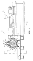
- FIG. 7 shows a turret clamp similar to that disclosed in FIGS. 1-6.
- the injection unit is not shown.
- a fixed platen 61 is mounted on the clamp base 62 and supports mold stationary half 63, which includes cavity 64.
- a turret block 65 is mounted on journals carried in a movable carriage, not shown.
- the block carries two mold halves 66 and 67 and typically the cores 68a and 68b.
- the turret block is connected via a linkage means, as rod 69, to a sliding plate 70, that slides in a track 71, mounted to the fixed platen 61.
- Blocking plate 72 and associated actuating cylinder 73 are also mounted to the fixed platen such that the plate 72 can block the sliding plate 70 in one of its positions.
- FIG. 7 shows a single core 68a and 68b attached to each mold half 66 and 67, respectively, naturally, a plurality of cores can be employed mating with a plurality of cavities, as in FIGS. 1-6.
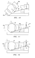
- FIG. 8 shows the turret block 65 moving away, indirection of arrow "A" from the fixed platen 61 by means of conventional cylinders, not shown.
- the rod 69 and sliding plate 70 move with it until the sliding plate 70 reaches the end of the travel permitted by track 71.
- This distance corresponds to the mold opening distance "D” that is required in order for the core 68a, and molded part 75 thereon, to clear the cavity 74 before rotation of the core is permitted.
- the turret block continues to move in the direction of arrow "A” and now because the end of rod 69 is blocked from further motion the turret is caused to rotate in a clockwise direction in the direction of arrow "B", see FIG. 9.
- FIG. 9 shows the turret 65 having moved to its furthest position away from the fixed platen 61 and rod 69 has caused a rotation of 90 degrees of the block.
- the molded part 75 can be ejected from the core 68a by conventional means, such as mechanical stripping or air ejection.
- ejection of the part occurs "on the fly” without stopping rotation of the turret block.
- the ejected parts fall under the mold and are captured in a take away conveyor underneath the machine, not shown.
- FIG. 10 shows this condition in which the turret block 65 is now moving towards the fixed platen 61 in direction of arrow "C" while clockwise rotary motion continues.
- the second set of cores 68b are now brought into alignment with the cavities 74.
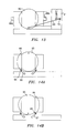
- FIGS. 14A and 14B show a preferred means of stopping the rotary motion of the block 65 quickly and accurately.
- the block has stopping faces 85 and 86 thereon which contact energy absorbers and positioning blocks 87 and 88, respectively, that are mounted on the turret carriage.
- the block rotates through 180 degrees and is accurately stopped and aligned for mold closing in each of its two positions.
- the block rotates clockwise on one cycle and then anti-clockwise on the subsequent cycle and alternately presents the two core sets 68a and 68b to the mold cavity 74.
- FIG. 11 shows the rotation of the block 65 completed and stopped while the turret block 65 continues to move toward the fixed platen 61 in the direction of arrow "C".
- blocking plate 72 is withdrawn by actuator 73, permitting sliding plate 70 to slide in track 71. This is shown in FIG. 12.
- the mold is closed and clamped ready for the next molding cycle to start as shown in FIG. 13.
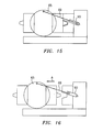
- FIG. 15 shows an alternate means of handling the initial mold open motion without rotation.
- rod 69 includes a cylinder 90 having sufficient stroke to permit mold open motion stroke "D" as shown in FIG. 8.
- cylinder 90 is energized to extend the length of rod 69.
- FIG. 16 shows cylinder 90 at its second position and rod 69 fully extended without rotation of the block having occurred.
- cylinder 90 would be energized to keep rod 69 fully extended until rotation was complete and then cylinder 90 would be de-energized to permit rod 69 to shorten in length as the cylinders completed the mold closing stroke.
- the mechanical rotary means shown here is substantially less costly than the electric servo drive means and its controls shown in FIGS. 1-6. Furthermore, because the mechanical means is linked to the opening and closing means no time is lost starting and stopping rotation, these actions occur simultaneously as the opening and closing motions of the turret block occur. In addition, ejection of the parts can occur during rotation of the block, again precluding the need to stop turret block motion during ejection.
- the accumulation of these time saving elements constitute a substantial saving in overall cycle time and make the machine competitive when compared to conventional machines used for molding thin wall articles in high speed cycles, typically 5 seconds or less. Other advantages then become factors when comparing this high speed turret machine with conventional high speed thin wall molding machines. These including the following:
- the second station opposed to mold cavity 64 may be used for secondary operations, such as pre-molding or post-molding operations, as temperature conditioning, label loading, liner loading, a finished article removal mechanism, etc.
- the stationary mold half 63 and fixed platen 61 may be vertically positioned instead of horizontally positioned as shown in FIG. 7.
Landscapes
- Engineering & Computer Science (AREA)
- Manufacturing & Machinery (AREA)
- Mechanical Engineering (AREA)
- Moulds For Moulding Plastics Or The Like (AREA)
- Injection Moulding Of Plastics Or The Like (AREA)
Applications Claiming Priority (2)
| Application Number | Priority Date | Filing Date | Title |
|---|---|---|---|
| US08/847,895 US5837301A (en) | 1997-04-28 | 1997-04-28 | Injection molding machine having a high speed turret |
| US847895 | 1997-04-28 |
Publications (2)
| Publication Number | Publication Date |
|---|---|
| EP0876892A2 true EP0876892A2 (fr) | 1998-11-11 |
| EP0876892A3 EP0876892A3 (fr) | 1999-12-15 |
Family
ID=25301758
Family Applications (1)
| Application Number | Title | Priority Date | Filing Date |
|---|---|---|---|
| EP98810363A Withdrawn EP0876892A3 (fr) | 1997-04-28 | 1998-04-24 | Tête revolver à vitesse élevée |
Country Status (4)
| Country | Link |
|---|---|
| US (1) | US5837301A (fr) |
| EP (1) | EP0876892A3 (fr) |
| JP (1) | JPH10323873A (fr) |
| CA (1) | CA2235893A1 (fr) |
Cited By (1)
| Publication number | Priority date | Publication date | Assignee | Title |
|---|---|---|---|---|
| EP1013398A1 (fr) * | 1998-12-21 | 2000-06-28 | Husky Injection Molding Systems Ltd. | Dispositif de refroidissement attaché à machine rotative |
Families Citing this family (31)
| Publication number | Priority date | Publication date | Assignee | Title |
|---|---|---|---|---|
| CA2255096C (fr) * | 1998-04-30 | 2002-01-22 | Husky Injection Molding Systems Ltd. | Colonne de guidage pour presse a injection |
| US6059557A (en) * | 1998-10-07 | 2000-05-09 | Husky Injection Molding Systems Ltd. | Cooling device attached to index machine |
| US6129883A (en) * | 1998-12-18 | 2000-10-10 | Husky Injection Molding Systems Ltd. | Vertical clamp index machine |
| US6168416B1 (en) | 1998-12-22 | 2001-01-02 | Husky Injection Molding Systems Ltd. | Cooling device for molded articles |
| US6143225A (en) * | 1999-03-03 | 2000-11-07 | Husky Injection Molding Systems Ltd. | Turret cooling block for an index machine |
| US6503075B1 (en) * | 2000-08-24 | 2003-01-07 | Husky Injection Molding Systems, Ltd. | Stack mold carrier and rotary turret with services provided by a rotary union |
| US7191684B2 (en) | 2000-09-14 | 2007-03-20 | Elder Jack E | Mechanism and method for rotating a machine tool element |
| US20030017230A1 (en) * | 2001-07-18 | 2003-01-23 | Akira Yoshinaga | Clamping unit |
| US7122143B2 (en) | 2001-09-28 | 2006-10-17 | Mcneil-Ppc, Inc. | Methods for manufacturing dosage forms |
| NZ532096A (en) | 2001-09-28 | 2006-10-27 | Mcneil Ppc Inc | Dosage forms having an inner core and outer shell with different shapes |
| US6982094B2 (en) * | 2001-09-28 | 2006-01-03 | Mcneil-Ppc, Inc. | Systems, methods and apparatuses for manufacturing dosage forms |
| US7323192B2 (en) * | 2001-09-28 | 2008-01-29 | Mcneil-Ppc, Inc. | Immediate release tablet |
| US6742646B2 (en) | 2001-09-28 | 2004-06-01 | Mcneil-Ppc, Inc. | Systems, methods and apparatuses for manufacturing dosage forms |
| US7217381B2 (en) | 2001-09-28 | 2007-05-15 | Mcneil-Ppc, Inc. | Systems, methods and apparatuses for manufacturing dosage forms |
| US7838026B2 (en) | 2001-09-28 | 2010-11-23 | Mcneil-Ppc, Inc. | Burst-release polymer composition and dosage forms comprising the same |
| US6767200B2 (en) * | 2001-09-28 | 2004-07-27 | Mcneil-Ppc, Inc. | Systems, methods and apparatuses for manufacturing dosage forms |
| US6837696B2 (en) * | 2001-09-28 | 2005-01-04 | Mcneil-Ppc, Inc. | Apparatus for manufacturing dosage forms |
| WO2004033175A2 (fr) * | 2002-10-11 | 2004-04-22 | Taylors Industrial Services, L.L.C. | Machine de moulage a tourelle rotative et procede associe |
| US7052645B2 (en) | 2003-09-26 | 2006-05-30 | Kessler Containers, Inc. | Blow molding apparatus and method |
| US20050074514A1 (en) * | 2003-10-02 | 2005-04-07 | Anderson Oliver B. | Zero cycle molding systems, methods and apparatuses for manufacturing dosage forms |
| JP4261473B2 (ja) * | 2004-12-24 | 2009-04-30 | 住友重機械工業株式会社 | 成形方法及び成形機 |
| US7364683B2 (en) * | 2005-01-11 | 2008-04-29 | Advance Tool, Inc. | Rotary automatic transfer rail for injection molding |
| US8673352B2 (en) | 2005-04-15 | 2014-03-18 | Mcneil-Ppc, Inc. | Modified release dosage form |
| US7320582B2 (en) * | 2006-01-03 | 2008-01-22 | Husky Injection Molding Systems Ltd. | Encapsulating fibrous inserts with molding material |
| US7465166B2 (en) * | 2006-08-11 | 2008-12-16 | Husky Injection Molding Systems Ltd. | Injection molding system having a hot runner assembly |
| US8747100B2 (en) | 2012-01-31 | 2014-06-10 | Tech Mold, Inc. | Multiple-component injection mold assembly and method |
| DE102013006713A1 (de) | 2013-04-19 | 2014-10-23 | Otto Männer Innovation GmbH | Multishot-Spitzgussvorrichtung |
| BR112015028373A2 (pt) * | 2013-05-13 | 2017-07-25 | Procter & Gamble | sistema de moldagem por injeção em pressão baixa e constante com cavidades de moldagem posicionadas de forma variável |
| CN113165043B (zh) | 2018-07-24 | 2024-02-13 | 佳能弗吉尼亚股份有限公司 | 用于一起滑动的不同结构的连接 |
| WO2020210253A1 (fr) * | 2019-04-11 | 2020-10-15 | Canon Virginia, Inc. | Système de moulage par injection avec dispositifs de convoyage pour insérer ou éjecter des moules |
| CN111055425B (zh) * | 2019-11-21 | 2024-11-15 | 重庆豪斯特汽车零部件有限公司 | 一种可倾斜的成型模具和具有其的模具车 |
Family Cites Families (28)
| Publication number | Priority date | Publication date | Assignee | Title |
|---|---|---|---|---|
| DE401671C (de) * | 1922-06-23 | 1924-09-06 | Franz Klima | Revolverfalzziegelpresse mit Handantrieb |
| GB523477A (en) * | 1939-01-02 | 1940-07-16 | Molding Service Inc | Improvements in apparatus for moulding plastic materials |
| US2333056A (en) * | 1940-12-16 | 1943-10-26 | Hydraulic Dev Corp Inc | Turret type injection press |
| BE755186A (fr) * | 1969-09-09 | 1971-02-01 | American Can Co | Spuitgietproces |
| US3730665A (en) * | 1969-11-19 | 1973-05-01 | Fortin Latchford Ltd | Molding apparatus |
| US3833329A (en) * | 1970-11-04 | 1974-09-03 | Eastman Kodak Co | Injection molding apparatus |
| US3881855A (en) * | 1973-01-16 | 1975-05-06 | Francis Farkas | Injection blow molding apparatus |
| GB1480951A (en) * | 1974-01-08 | 1977-07-27 | Kaufman A | Apparatus for and method of injection blow moulding |
| DE2456008A1 (de) * | 1974-11-27 | 1976-08-12 | Horst Nicke | Formwerkzeug zum herstellen von spritzgusserzeugnissen aus thermoplastischen kunststoffen |
| US4243362A (en) * | 1979-06-04 | 1981-01-06 | Globe-Union Inc. | Composite molding apparatus for articles from two materials having a rotary mold block which includes pins for providing core areas |
| US4330257A (en) * | 1979-11-15 | 1982-05-18 | Husky Injection Molding Systems, Inc. | Turret-type injection-molding machine |
| US4363619A (en) * | 1980-07-28 | 1982-12-14 | Farrell Patent Company | Apparatus for making wide mouth container |
| US4449913A (en) * | 1981-02-23 | 1984-05-22 | The Continental Group, Inc. | Rotary injection turret for the making of preforms |
| US4370124A (en) * | 1981-06-17 | 1983-01-25 | Buja Frederick J | Modular rotary molding machine |
| JPS5811117A (ja) * | 1981-07-14 | 1983-01-21 | Sumitomo Heavy Ind Ltd | 射出延伸吹込成形装置 |
| US4444711A (en) * | 1981-12-21 | 1984-04-24 | Husky Injection Molding Systems Ltd. | Method of operating a two-shot injection-molding machine |
| DE3620175A1 (de) * | 1986-06-14 | 1987-12-17 | Kloeckner Ferromatik Desma | Spritzgiessmaschine mit mindestens zwei plastifizier- und einspritzeinheiten |
| US4836767A (en) * | 1987-11-25 | 1989-06-06 | Husky Injection Molding System, Ltd. | Swing plate molding machine |
| US5033955A (en) * | 1990-10-10 | 1991-07-23 | Cincinnati Milacron Inc. | Article mold handling apparatus |
| JP3297809B2 (ja) * | 1990-11-05 | 2002-07-02 | 株式会社山城精機製作所 | 成形機における金型装置 |
| JPH04348916A (ja) * | 1991-04-17 | 1992-12-03 | Komatsu Ltd | 調芯装置付きの型締装置 |
| US5238389A (en) * | 1991-06-03 | 1993-08-24 | Husky Injection Molding Systems Ltd. | Apparatus for preparing a hollow plastic article |
| DE4141259C2 (de) * | 1991-12-14 | 1993-10-07 | Hemscheidt Maschtech Schwerin | Formschließeinrichtung für Spritzgießmaschinen |
| DE4209392C2 (de) * | 1992-03-23 | 1995-10-12 | Krauss Maffei Ag | Formschließvorrichtung für eine Spritzgießmaschine |
| JP3227888B2 (ja) * | 1993-04-16 | 2001-11-12 | 松下電器産業株式会社 | 樹脂成形法及びその樹脂を用いた送風機羽根車 |
| US5383780A (en) * | 1993-09-27 | 1995-01-24 | Husky Injection Molding Systems Ltd. | Apparatus for forming threaded molded article |
| US5728409A (en) * | 1996-03-06 | 1998-03-17 | Husky Injection Molding Systems Ltd. | Turret article molding machine |
| US5817345A (en) * | 1996-03-06 | 1998-10-06 | Husky Injection Molding System Ltd. | Turrent article molding machine and method of use |
-
1997
- 1997-04-28 US US08/847,895 patent/US5837301A/en not_active Expired - Fee Related
-
1998
- 1998-04-24 EP EP98810363A patent/EP0876892A3/fr not_active Withdrawn
- 1998-04-27 CA CA002235893A patent/CA2235893A1/fr not_active Abandoned
- 1998-04-28 JP JP10117673A patent/JPH10323873A/ja active Pending
Cited By (1)
| Publication number | Priority date | Publication date | Assignee | Title |
|---|---|---|---|---|
| EP1013398A1 (fr) * | 1998-12-21 | 2000-06-28 | Husky Injection Molding Systems Ltd. | Dispositif de refroidissement attaché à machine rotative |
Also Published As
| Publication number | Publication date |
|---|---|
| EP0876892A3 (fr) | 1999-12-15 |
| CA2235893A1 (fr) | 1998-10-28 |
| US5837301A (en) | 1998-11-17 |
| JPH10323873A (ja) | 1998-12-08 |
Similar Documents
| Publication | Publication Date | Title |
|---|---|---|
| US5837301A (en) | Injection molding machine having a high speed turret | |
| US5728409A (en) | Turret article molding machine | |
| EP1072379B1 (fr) | Moule d'injection | |
| US5750162A (en) | Turret article molding machine including blow molding station | |
| US6986653B2 (en) | Post mold cooling apparatus and method having transverse movement | |
| AU2003218841B2 (en) | Post mold cooling apparatus and method having rotational and transverse movement | |
| US6143225A (en) | Turret cooling block for an index machine | |
| JP4339887B2 (ja) | 定盤装着成形後冷却装置 | |
| US5951936A (en) | Compact and torque free side entry trolley robot | |
| US6503075B1 (en) | Stack mold carrier and rotary turret with services provided by a rotary union | |
| US7198480B2 (en) | Injection molding system with high production efficiency and low system cost | |
| CA2289149C (fr) | Dispositif et procede de refroidissement d'articles moules | |
| US20040119205A1 (en) | Rotating turret molding machine and associated process | |
| WO2009143600A1 (fr) | Système de moulage par injection et procédé de moulage par injection | |
| JP2530398B2 (ja) | 射出延伸吹込成形装置 |
Legal Events
| Date | Code | Title | Description |
|---|---|---|---|
| PUAI | Public reference made under article 153(3) epc to a published international application that has entered the european phase |
Free format text: ORIGINAL CODE: 0009012 |
|
| AK | Designated contracting states |
Kind code of ref document: A2 Designated state(s): AT BE CH CY DE DK ES FI FR GB GR IE IT LI LU MC NL PT SE |
|
| AX | Request for extension of the european patent |
Free format text: AL;LT;LV;MK;RO;SI |
|
| PUAL | Search report despatched |
Free format text: ORIGINAL CODE: 0009013 |
|
| AK | Designated contracting states |
Kind code of ref document: A3 Designated state(s): AT BE CH CY DE DK ES FI FR GB GR IE IT LI LU MC NL PT SE |
|
| AX | Request for extension of the european patent |
Free format text: AL;LT;LV;MK;RO;SI |
|
| AKX | Designation fees paid | ||
| REG | Reference to a national code |
Ref country code: DE Ref legal event code: 8566 |
|
| STAA | Information on the status of an ep patent application or granted ep patent |
Free format text: STATUS: THE APPLICATION IS DEEMED TO BE WITHDRAWN |
|
| 18D | Application deemed to be withdrawn |
Effective date: 20000616 |