EP0876964A1 - Luftdichter Behälter mit Glockendeckel - Google Patents
Luftdichter Behälter mit Glockendeckel Download PDFInfo
- Publication number
- EP0876964A1 EP0876964A1 EP98108319A EP98108319A EP0876964A1 EP 0876964 A1 EP0876964 A1 EP 0876964A1 EP 98108319 A EP98108319 A EP 98108319A EP 98108319 A EP98108319 A EP 98108319A EP 0876964 A1 EP0876964 A1 EP 0876964A1
- Authority
- EP
- European Patent Office
- Prior art keywords
- bell jar
- base plate
- covering
- air
- container
- Prior art date
- Legal status (The legal status is an assumption and is not a legal conclusion. Google has not performed a legal analysis and makes no representation as to the accuracy of the status listed.)
- Withdrawn
Links
- 238000007789 sealing Methods 0.000 claims abstract description 26
- 239000000463 material Substances 0.000 description 7
- 235000012431 wafers Nutrition 0.000 description 5
- XUIMIQQOPSSXEZ-UHFFFAOYSA-N Silicon Chemical compound [Si] XUIMIQQOPSSXEZ-UHFFFAOYSA-N 0.000 description 4
- 239000004065 semiconductor Substances 0.000 description 4
- 229910052710 silicon Inorganic materials 0.000 description 4
- 239000010703 silicon Substances 0.000 description 4
- 238000011109 contamination Methods 0.000 description 3
- 239000000428 dust Substances 0.000 description 3
- 239000002245 particle Substances 0.000 description 3
- 239000004820 Pressure-sensitive adhesive Substances 0.000 description 2
- 239000000047 product Substances 0.000 description 2
- 239000000853 adhesive Substances 0.000 description 1
- 230000001070 adhesive effect Effects 0.000 description 1
- 230000006835 compression Effects 0.000 description 1
- 238000007906 compression Methods 0.000 description 1
- 238000007796 conventional method Methods 0.000 description 1
- 239000013067 intermediate product Substances 0.000 description 1
- 238000004519 manufacturing process Methods 0.000 description 1
- 238000000034 method Methods 0.000 description 1
- 238000003825 pressing Methods 0.000 description 1
- 239000007787 solid Substances 0.000 description 1
- 238000003860 storage Methods 0.000 description 1
Images


Classifications
-
- B—PERFORMING OPERATIONS; TRANSPORTING
- B65—CONVEYING; PACKING; STORING; HANDLING THIN OR FILAMENTARY MATERIAL
- B65D—CONTAINERS FOR STORAGE OR TRANSPORT OF ARTICLES OR MATERIALS, e.g. BAGS, BARRELS, BOTTLES, BOXES, CANS, CARTONS, CRATES, DRUMS, JARS, TANKS, HOPPERS, FORWARDING CONTAINERS; ACCESSORIES, CLOSURES, OR FITTINGS THEREFOR; PACKAGING ELEMENTS; PACKAGES
- B65D45/00—Clamping or other pressure-applying devices for securing or retaining closure members
- B65D45/02—Clamping or other pressure-applying devices for securing or retaining closure members for applying axial pressure to engage closure with sealing surface
-
- B—PERFORMING OPERATIONS; TRANSPORTING
- B65—CONVEYING; PACKING; STORING; HANDLING THIN OR FILAMENTARY MATERIAL
- B65D—CONTAINERS FOR STORAGE OR TRANSPORT OF ARTICLES OR MATERIALS, e.g. BAGS, BARRELS, BOTTLES, BOXES, CANS, CARTONS, CRATES, DRUMS, JARS, TANKS, HOPPERS, FORWARDING CONTAINERS; ACCESSORIES, CLOSURES, OR FITTINGS THEREFOR; PACKAGING ELEMENTS; PACKAGES
- B65D39/00—Closures arranged within necks or pouring openings or in discharge apertures, e.g. stoppers
- B65D39/12—Closures arranged within necks or pouring openings or in discharge apertures, e.g. stoppers expansible, e.g. inflatable
-
- B—PERFORMING OPERATIONS; TRANSPORTING
- B65—CONVEYING; PACKING; STORING; HANDLING THIN OR FILAMENTARY MATERIAL
- B65D—CONTAINERS FOR STORAGE OR TRANSPORT OF ARTICLES OR MATERIALS, e.g. BAGS, BARRELS, BOTTLES, BOXES, CANS, CARTONS, CRATES, DRUMS, JARS, TANKS, HOPPERS, FORWARDING CONTAINERS; ACCESSORIES, CLOSURES, OR FITTINGS THEREFOR; PACKAGING ELEMENTS; PACKAGES
- B65D53/00—Sealing or packing elements; Sealings formed by liquid or plastics material
- B65D53/02—Collars or rings
Definitions
- the present invention relates to an air-tightly sealable container with a bell jar covering provided with a sealing mechanism between the bell jar covering and the base plate on which the bell jar covering is mounted to be used for storage and transportation of various precision products to be kept absolutely free from contamination with atmospheric dust particles such as semiconductor silicon wafers.
- the routine delivery system of semiconductor silicon wafers is that the silicon wafers as produced in the plant of a wafer producer are packaged in a specially designed container for transportation and transported therein to the plant of a manufacturer of semiconductor devices such as integrated circuits. Similar containers are used also within the plant of the device manufacturers in-house for the purpose of transfer of intermediate products from a line to a subsequent line for the next step of working.
- a semiconductor silicon wafer is a product of extremely high purity and must be kept away from any trace contamination on the base of which ultrafine and extremely delicate electronic circuits are to be built so that the container therefor must be provided with a very reliable sealing mechanism by means of which intrusion of any trace amount of particulate foreign matters such as dust particles can be completely prevented.
- One of the most traditional way to obtain an air-tight sealing condition of the opening in such a container is that a pressure-sensitive adhesive tape is attached along the seam line of the container body and the covering all around or an elastic gasket member is interposed between the open periphery of the container body and the periphery of the covering under an appropriate compression so as to eliminate any smallest interstice or gap, otherwise through which intrusion of dust particles may take place, to ensure a hermetic sealing condition.
- the sealing method by using a rubber gasket also requires a clamping mechanism by which the container body and the covering are engaged and fastened each to the other and an appropriate compressive force is applied to the elastic gasket member.
- the present invention accordingly has an object to provide a novel air-tightly sealable container with a sealing mechanism of a simple structure between a cylindrical bell jar covering and the base plate, on which the bell jar covering is mounted, by means of which mechanism a very reliable hermetic sealing condition can be ensured and which mechanism can be operated by an automatic machine for closing and opening of the container.
- the air-tightly sealable container with a sealing mechanism comprises:
- the above mentioned cylindrical bell jar covering as the part (A) need not have a circular cross section but the horizontal cross section thereof can be generally a square or rectangular form provided that each corner is rounded having a sufficiently large radius of curvature so that the elastic sealing member as the part (C) can fit the groove around the base plate as the part (B).
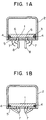
- Figures 1A and 1B each illustrate the bell jar container of the invention by an axial cross sectional view in an open state and sealed state, respectively.
- Figures 2A and 2B each illustrate the bell jar container of the invention in another embodiment by an axial cross sectional view with the bell jar covering lifted above the base plate and mounted on the base plate to establish a sealed state, respectively.
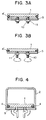
- Figures 3A and 3B each illustrate the bell jar container (bell jar covering not shown) of the invention in a further different embodiment showing an assembly of the base plate and the pressing plate corresponding to an open and sealed states, respectively, of the container by an axial cross sectional view.
- Figure 4 is an axial cross sectional view of a still different embodiment of the inventive container.
- Figure 5 is an axial cross sectional view of the same container as shown in Figure 4 on use in an upside-down disposition.
- the air-tightly sealable bell jar container comprises, as the principal parts thereof, (A) a bell jar covering having, for example, a circular cross section and mountable on a base plate, (B) a circular base plate having a diameter smaller than the inner diameter of the bell jar covering and provided with an annular groove open downwardly and laterally, (C) an elastic sealing member such as an O-ring gasket of a rubbery material to fit the annular groove in the base plate and (D) a presser plate which presses the elastic sealing member against the base plate by (E) a mechanism such as cams or screw bolts and nuts to such an extent that the elastic sealing member is compressed and laterally bulged out to be brought into contact with the inner wall of the bell jar covering mounted on the base plate to give an air-tight sealing condition between the base plate and the inner wall of the bell jar covering.
- A a bell jar covering having, for example, a circular cross section and mountable on a base plate
- B a circular base plate having a diameter
- the air-tightly sealable bell jar container of the invention is illustrated by making reference to the accompanying drawing.
- the following description is given by assuming that the bell jar covering has a circular cross section, about the same description is applicable even when the bell jar covering has a noncircular cross section such as a generally rectangular cross section.
- Figures 1A and 1B are each an axial cross sectional view of the inventive bell jar container in an open and sealed state, respectively.
- the container comprises a circular base plate 1, on which the materials to be contained are mounted, and a bell jar covering 2, of which the inner diameter is slightly larger than the diameter of the base plate 1, mountable on the base plate 1 in such a fashion that the base plate 1 is entirely enveloped inside of the bell jar covering 2 mounted thereon leaving a small clearance therebetween and a presser plate 5 below the base plate 1.
- the base plate 1 is provided with an annular groove 3 along the outer periphery thereof in such a fashion that the groove 3 is open laterally and downwardly.
- An O-ring gasket 4 of a rubber fits the annular groove 3 with elastic resilience.
- a presser plate 5 is provided below the base plate 1 in such a fashion that the presser plate 5 is movable up and down by sliding on the rods 6,6 downwardly extending from the lower surface of the base plate 1 by operating the cams 7,7 pivotally supported on the rods 6,6 by means of the cam handles 8,8.
- Figures 2A and 2B are for the illustration of the inventive container in an embodiment similar to that illustrated in Figures 1A and 1B. While the bell jar covering 2 illustrated in Figures 1A and 1B has a smooth inner surface, the inner surface of the bell jar covering 2' in Figures 2A and 2B is not smoothly cylindrical but has an annular groove 9 around the lower portion of the covering 2'.
- Figures 1A and 1B and Figures 2A and 2B show an O-ring gasket 4 which is solid, i.e. not hollow, it is optional to use a hollow O-ring gasket 4' as is illustrated in Figures 3A and 3B provided that a reliable air-tight sealing condition can be obtained by the contact between the elastically deformed O-ring gasket 4' and the inner wall of the bell jar covering (not shown in Figures 3A and 3B).
- Figures 3A and 3B further illustrate an alternative mechanical means for fastening the base plate 1 and the presser plate 5, in place of the mechanism of cams illustrated in Figures 1A and 1B and Figures 2A and 2B, consisting of screw bolts 10,10 implanted in and extending downwardly from the base plate 1 and screw nuts 11,11 movable on the screw bolts 10,10.
- the O-ring gasket 4' When the nuts 11,11 are at the lower positions, the O-ring gasket 4' is in an uncompressed state, as is illustrated in Figure 3A, allowing free mounting and removal of the ball jar covering on and from the base plate 1 while, when the nuts are turned to push up the presser plate 5 against the base plate 1, as is illustrated in Figure 3B, the O-ring gasket 4' is upwardly compressed and bulged out laterally to be brought into contact with the inner wall of the bell jar covering.
- the presser plate 5 is assumed to have a diameter approximately equal to the diameter of the base plate 1 which is slightly smaller than the inner diameter of the bell jar covering 2. It is, however, optional that the presser plate 5 has a diameter smaller or larger than the diameter of the base plate 1.
- the diameter of the presser plate 5' can be larger than the inner diameter of the bell jar covering 2 so that the bell jar covering 2 can rest at the lower periphery thereof on the presser plate 5'.
- the embodiment of the inventive container illustrated in Figure 4, in which the presser plate 5' has a diameter larger than the inner diameter of the bell jar covering 2, can be used as being turned upsidedown so that, while, in the other embodiments described earlier, the materials to be contained in the container are placed on the base plate 1 and then the bell jar covering 2 is mounted thereon, the materials are first placed on the bottom of the bell jar covering in an upsidedown disposition and then the assembly of the base plate 1 and the presser plate 5 is mounted on the upper periphery of the covering 2 without a trouble of falling down into the bell jar covering 2.
- the bell jar container of the invention shown, for example, in Figure 4 can be used in an upside-down disposition.
- the bell jar covering 2 in Figure 4 is now the container bottom 2 in Figure 5 standing on the flat bottom and the presser plate 5 now serves as the covering.
- the material contained in the container naturally rests on the bottom of the container body 2.
Landscapes
- Engineering & Computer Science (AREA)
- Mechanical Engineering (AREA)
- Closures For Containers (AREA)
- Packaging Frangible Articles (AREA)
- Packages (AREA)
Applications Claiming Priority (2)
| Application Number | Priority Date | Filing Date | Title |
|---|---|---|---|
| JP119820/97 | 1997-05-09 | ||
| JP9119820A JPH10310158A (ja) | 1997-05-09 | 1997-05-09 | 容器の封止構造 |
Publications (1)
| Publication Number | Publication Date |
|---|---|
| EP0876964A1 true EP0876964A1 (de) | 1998-11-11 |
Family
ID=14771066
Family Applications (1)
| Application Number | Title | Priority Date | Filing Date |
|---|---|---|---|
| EP98108319A Withdrawn EP0876964A1 (de) | 1997-05-09 | 1998-05-07 | Luftdichter Behälter mit Glockendeckel |
Country Status (4)
| Country | Link |
|---|---|
| EP (1) | EP0876964A1 (de) |
| JP (1) | JPH10310158A (de) |
| KR (1) | KR19980086879A (de) |
| TW (1) | TW371290B (de) |
Cited By (5)
| Publication number | Priority date | Publication date | Assignee | Title |
|---|---|---|---|---|
| FR2788498A1 (fr) * | 1999-01-14 | 2000-07-21 | Didier Clement | Couvercle coulissant d'etancheite |
| US7416092B2 (en) | 2003-04-09 | 2008-08-26 | George Utz Holding Ag | Stackable transport box |
| CN107640430A (zh) * | 2017-09-25 | 2018-01-30 | 重庆市潼南区卧佛生态农业发展有限公司 | 密封盖 |
| CN109469729A (zh) * | 2018-12-18 | 2019-03-15 | 无锡刚正精密吸铸有限公司 | 超高压端盖 |
| CN110092074A (zh) * | 2019-06-03 | 2019-08-06 | 四川航天系统工程研究所 | 一种可调节密封程度的密封结构 |
Families Citing this family (4)
| Publication number | Priority date | Publication date | Assignee | Title |
|---|---|---|---|---|
| JP4498763B2 (ja) * | 2004-01-29 | 2010-07-07 | 紀伊産業株式会社 | 化粧料容器 |
| US7815067B2 (en) * | 2006-03-31 | 2010-10-19 | Helen Of Troy Limited | Container with sealable lid |
| FR2969127B1 (fr) * | 2010-12-21 | 2014-04-18 | Oreal | Dispositif de conditionnement d'un produit, notamment cosmetique, avec un organe d'etancheite |
| US11555791B2 (en) | 2019-12-03 | 2023-01-17 | Corning Incorporated | Chamber for vibrational and environmental isolation of thin wafers |
Citations (4)
| Publication number | Priority date | Publication date | Assignee | Title |
|---|---|---|---|---|
| US2462445A (en) * | 1944-09-26 | 1949-02-22 | Weiss Hugo | Airtight lid for containers |
| DE876342C (de) * | 1949-03-17 | 1953-05-11 | Louis Dipl-Ing Schmid | Behaelter-Verschluss-Schlauch |
| EP0070266A1 (de) * | 1981-07-09 | 1983-01-19 | Mediplast AB | Dichtungseinrichtung |
| DE3804986A1 (de) * | 1988-02-18 | 1989-08-31 | Hermann Thoene | Vacuumdichte deckelkombination fuer aufbewahrungsdosen |
-
1997
- 1997-05-09 JP JP9119820A patent/JPH10310158A/ja active Pending
-
1998
- 1998-05-02 TW TW087106797A patent/TW371290B/zh active
- 1998-05-07 EP EP98108319A patent/EP0876964A1/de not_active Withdrawn
- 1998-05-08 KR KR1019980016472A patent/KR19980086879A/ko not_active Withdrawn
Patent Citations (4)
| Publication number | Priority date | Publication date | Assignee | Title |
|---|---|---|---|---|
| US2462445A (en) * | 1944-09-26 | 1949-02-22 | Weiss Hugo | Airtight lid for containers |
| DE876342C (de) * | 1949-03-17 | 1953-05-11 | Louis Dipl-Ing Schmid | Behaelter-Verschluss-Schlauch |
| EP0070266A1 (de) * | 1981-07-09 | 1983-01-19 | Mediplast AB | Dichtungseinrichtung |
| DE3804986A1 (de) * | 1988-02-18 | 1989-08-31 | Hermann Thoene | Vacuumdichte deckelkombination fuer aufbewahrungsdosen |
Cited By (5)
| Publication number | Priority date | Publication date | Assignee | Title |
|---|---|---|---|---|
| FR2788498A1 (fr) * | 1999-01-14 | 2000-07-21 | Didier Clement | Couvercle coulissant d'etancheite |
| US7416092B2 (en) | 2003-04-09 | 2008-08-26 | George Utz Holding Ag | Stackable transport box |
| CN107640430A (zh) * | 2017-09-25 | 2018-01-30 | 重庆市潼南区卧佛生态农业发展有限公司 | 密封盖 |
| CN109469729A (zh) * | 2018-12-18 | 2019-03-15 | 无锡刚正精密吸铸有限公司 | 超高压端盖 |
| CN110092074A (zh) * | 2019-06-03 | 2019-08-06 | 四川航天系统工程研究所 | 一种可调节密封程度的密封结构 |
Also Published As
| Publication number | Publication date |
|---|---|
| TW371290B (en) | 1999-10-01 |
| JPH10310158A (ja) | 1998-11-24 |
| KR19980086879A (ko) | 1998-12-05 |
Similar Documents
| Publication | Publication Date | Title |
|---|---|---|
| US6170690B1 (en) | Air-tightly sealable container with bell jar covering | |
| US6419482B1 (en) | Opening and closing apparatus of an opening and closing lid of a box accommodating an object to be processed and a processing system of an object to be processed | |
| US4900214A (en) | Method and apparatus for transporting semiconductor wafers | |
| KR970012986A (ko) | 기판처리장치 | |
| KR100567507B1 (ko) | 박판 지지 용기용 덮개, 박판 지지 용기 및 간이 착탈 기구 | |
| KR100637967B1 (ko) | 박판의 수납 및 운송 용기 | |
| US5358337A (en) | Load bearing ball | |
| US20230128509A1 (en) | Wafer carrier, wafer access device and wafer carrier and access assembly having the same | |
| KR19980086879A (ko) | 원통형 덮개를 구비한 기밀 용기 | |
| CN106816401B (zh) | 一种微环境与晶圆盒之间接口的密封装置及密封方法 | |
| US7001129B2 (en) | Loadlock apparatus and structure for creating a seal between an elevator drive shaft and the loadlock chamber thereof | |
| JP3418680B2 (ja) | 加熱プレス用チャンバ | |
| JPH0737794A (ja) | 真空内駆動装置 | |
| JPH0594766U (ja) | 気密試料容器 | |
| JP2022076243A (ja) | 開閉部材 | |
| JPH0737318Y2 (ja) | 枚葉ウエハ処理装置用ウエハ保持機構 | |
| CN221783183U (zh) | 一种应用于Load port载台的晶舟放置装置 | |
| KR101935400B1 (ko) | 제품 테스트 핸들러 | |
| JPH0229065Y2 (de) | ||
| JP2799727B2 (ja) | 電子部品のリード矯正装置 | |
| JPH0322082Y2 (de) | ||
| JPH04282848A (ja) | 半導体装置の製造装置 | |
| KR100309698B1 (ko) | 스탠더드 메커니컬 인터페이스 시스템의 그리퍼 | |
| KR20250019414A (ko) | 그리퍼 및 이송장치 | |
| JPH04112789U (ja) | 吸着装置 |
Legal Events
| Date | Code | Title | Description |
|---|---|---|---|
| PUAI | Public reference made under article 153(3) epc to a published international application that has entered the european phase |
Free format text: ORIGINAL CODE: 0009012 |
|
| AK | Designated contracting states |
Kind code of ref document: A1 Designated state(s): DE GB |
|
| AX | Request for extension of the european patent |
Free format text: AL;LT;LV;MK;RO;SI |
|
| 17P | Request for examination filed |
Effective date: 19990227 |
|
| AKX | Designation fees paid |
Free format text: DE GB |
|
| 17Q | First examination report despatched |
Effective date: 20000711 |
|
| STAA | Information on the status of an ep patent application or granted ep patent |
Free format text: STATUS: THE APPLICATION IS DEEMED TO BE WITHDRAWN |
|
| 18D | Application deemed to be withdrawn |
Effective date: 20010616 |